Digital Thermometer - Part 16 Microcontroller Basics (PIC10F200)
Published
Note: Microchip recently made some changes and their newer IDE versions use the XC8 compiler for Assembly, whereas all sample code here is created for the MPASM compiler. However, the sample code has been ported to XC8 by user tinyelect on our Discord channel (to whom we are extremely grateful!) and the XC8 version of the code is at the bottom of this tutorial for your reference. To see the changes needed to switch from MPASM to XC8, please check out the process that he shared.
Hi there! Today I want to present to you another meaty tutorial about creating a thermometer based on the very popular DS18B20 sensor and a 7-segment LED indicator. You may ask, how we’re going to connect the 7-segment indicator to our small microcontroller if it has a lot of pins? Well, fortunately for us, the company with the ambitious name “Titan Micro Electronics” designed the TM1637 chip which allows us to connect to a 7-segment LED display using just 2 wires (surprisingly for me this chip has become very widespread despite its disadvantages, about which I’ll discuss later). So we will use one GPIO to connect to the sensor, and another two GPIOs to connect to the display, which works for us.
Let’s start with the TM1637 module, as it has an “almost I2C” interface. The look of the module with the LED indicator is shown in figure 1.

As you can see, the indicator is designed to be used as a clock, as it has only a colon in the middle, and not decimal points, but it’s OK for us as we will not display the fractional part of the temperature. The price of this module starts from $0.66 at Aliexpress.
As I mentioned. the communication interface is “almost I2C”. What does that mean? Physically, it’s the same as I2C: it uses two wires, which are called DIO and CLK instead of SDA and SCL correspondingly. Also, it has very similar signalling: the same Start and Stop conditions, the data byte is also followed by the acknowledgement bit. But there are certain differences which make this module incompatible with the I2C bus:
- The module doesn’t have an address, so it considers any packet to be addressed to it, and happily sets the ACK bit after each byte. This can be very confusing if you connect it in parallel with other I2C devices, so please don’t do this.
- The bit order is LSB first unlike normal I2C where the data byte goes MSB first.
Why the guys from “Titan Micro Electronics” designed their device in such a way is a mystery to me, but we have what we have. I could find a module with normal I2C support but, for some reason, they are more expensive and less widespread, so we will use this one.
So what does this chip offer us? Actually, its functionality is quite good (which is typical for cheap Chinese chips). It allows us to connect up to six 7-segment LED indicators with the common anode, and up to 16 buttons, while also allowing us to set the brightness of the LED indicator. For more detail you can refer to the datasheet.
I will describe only the part that controls the LED display. So communication between the microcontroller and the TM1637 chip consists of three parts.
First, we need to send the so-called “Command 1” which for us “sets the data” (0x4...). In fact, we select if we are going to control the display or read the buttons, and also adjust some parameters. In our program, we will always set this command as 0x40 which means write data to display register (bit 1 = 0), automatic address adding (bit 2 = 0), and normal mode (bit 3 = 0).
Second, we send “Command 2”, which “sets the address” (0xC…). As we will always start with the first indicator, we will send address 0, and the command byte will be 0xC0. The address is followed by the data to be indicated, so we will send 4 bytes that will represent the data to display.
Third, we send the “Command 3”, which is “display control” (0x8…). It allows us to set the display brightness by changing the lower 3 bits - 0b1000 is the lowest brightness, 0b1111 is full brightness. We will send the value 0x8F to set to full brightness.
Let’s now consider how to display something using this module. As I mentioned before, the data to be displayed is followed by “Command 2”. Each data byte (obviously) consists of 8 bits, each of which corresponds to one of the segments of the indicator: 0 - A, 1 - B, 2 - C, 3 - D, 4 - E, 5 - F, 6 - G, 7 - DP (see figure 2).

To light up some a segment you need to set the corresponding bit to 1. For instance, if you want to display the digit 3, you need to light up segments A, B, C, D, and G, thus the code will be 0b01001111.
I guess that's enough information about the TM1637 module and how to operate it at the moment. Let’s now switch to the DS18B20 sensor.
This very popular sensor was designed by the Dallas Semiconductor company (that’s why the sensor’s name starts with the ‘DS’) which was bought by the Maxim Integrated corporation in 2001.
The price of the sensor starts from $0.60 at Aliexpress. The appearance of the sensor is shown in figure 3.

As you see, it’s just a chip in a TO-92 package. There are also modifications in the uSOP-8 and SOIC-8 packages (fig. 4, taken from the datasheet).

The DS18B20 chip has only 3 active pins - two are used for power (VDD and GND), and one (DQ) is used for communication with the microcontroller. This chip uses a special digital interface called 1-wire, which was also developed by Dallas Semiconductor. This interface is not as widespread as UART, I2C or SPI, and the majority of the microcontrollers don’t have a hardware module which supports it. This interface has some advantages which make it popular though. The most obvious of them is the low number of pins: except for power, it uses just one microcontroller pin. Moreover, you can connect several devices in parallel like the I2C bus. And furthermore, the 1-wire bus supports so called “parasitic power”, which means that devices can use the DQ pin both for powering and for sending the data, thus they need just two wires to connect.
Like the I2C bus, 1-wire also has the Master-Slave architecture, which means that all communications are inspired by the Master device while Slave devices just follow its commands. As I said before, there can be several Slave devices connected in parallel. Each 1-wire device has a unique 64-bit address programmed at the factory, so there is no chance that you connect two devices with the same address to the same bus. The schematic diagram of the connection between the Master and the Slave via 1-wire bus is shown in figure 5, taken from the datasheet.

As you see, the connection is similar to the I2C bus. Here we also have the pull-up resistor which should be 4.7 kOhm. The devices also have the open-collector output, and that means we will also need to reconfigure the microcontroller’s pin as an input (to send 1 to the bus) or as an output (to send 0 to the bus).
Let’s now see how to communicate using 1-wire. Like in I2C bus, 1-wire also has a special condition which always should be issued to start the communication. This condition is called Reset (figure 6, taken from the datasheet).

Unlike the I2C bus. 1-wire doesn’t have the clock pulses, so to synchronize the Master and the Slave devices, they both need to strictly follow the specified timings.
To start the Reset, the Master pulls the bus down for at least 480 us. Then it releases the bus and waits for 15-60 us. If any device is present on the bus, it will respond to this reset pulse by pulling the bus down for 60-240 us. So after sending the Reset pulse, the Master device should wait for about 60 us and then read the bus state. If it’s 0, that means that the Slave device is present, and ready for the communication. If the bus state is 1, then there are no Slave devices, or they are disabled. After the Master reads the bus state it should wait for about 410 us to make sure that the Slave has released the bus.
After the start condition the Master sends the data. Usually the first byte is the command (we already mentioned them and will consider them in greater detail later). Sending a 1 or 0 to the bus also requires strict timings (figure 7, taken from the datasheet).

To write 0 to the bus, the Master pulls the line down for at least 60 us, then it releases the bus for at least 1us (10-15 us is OK). To write 1 to the bus, the Master pulls the line down for at least 1 us (from my experience 8-10 us is OK as well) and then releases the bus for at least 60 us.
Finally, let’s see how reading from the bus is implemented (figure 8, taken from the datasheet).

The Master device should set the bus low for more than 1 us (3-5 us is OK) and then release it. Then the Slave should either pull the bus low if it transmits 0, or leave the bus high if it transmits 1. The Master waits for about 15 us and then reads the bus state and saves it. Finally, the Master should wait for at least 45 us to make sure that the Slave has released the bus, and then it can start the new time slot to read the next bit.
That’s all about the 1-wire bus signalling. Now let’s briefly consider the logic level of the interface.
After sending the Reset pulse and receiving the presence confirmation from the Slave, Master should send one of the so called ROM commands. These commands are used to select one of the devices that are present on the bus, using their unique 64-bit address. I will not describe them here, you can always refer to the datasheet. The only one command that we will use is called Skip ROM and has the code 0xCC. This command is used to send the data to all the devices that are present on a bus, and as long as we will have only one device, we can use it.
After sending the ROM command, the Master issues one of the device-specific commands. In our program we will use two of the commands specific for the DS18B20 sensor: Convert T (0x44) and Read Scratchpad (0xBE). The first one is used to start the temperature measurement and conversion. This process can take up to 750 ms. So it’s better to wait for about 1 second before reading the value. The second command is used to read the so-called Scratchpad. It consists of nine bytes, and includes the temperature value, the threshold values, the configuration register and the CRC byte. We will read just the two first bytes which represent the lower and the upper byte of the temperature correspondingly.
Speaking of the temperature, it’s stored in the format shown in figure 9, taken from the datasheet.

As long as we develop the home thermometer, we will consider that the temperature is above 0, and that means that the sign bits are 0. Also, we don’t need the fractional part of the temperature. So we need to read the 16-bit value and then shift it 4 bits to the right to get the temperature in Centigrade.
And that’s really all we need to know to make and program the thermometer. Let’s now consider the schematic diagram of the device (figure 10).

So the schematics are quite simple: the microcontroller PIC10F200 (DD1); the DS18B20 sensor (DD2) which DQ pin is connected to the GP2 and pulled up by the 4.7 kOhm resistor R1; the TM1637 module (X2) which CLK pin is connected to GP1, and DIO pin is connected to GP0. The TM1637 module has pull-up resistors on-board, so we don’t need any external resistors.
Both DS18B20 and TM1637 work well with the supply voltage 5V, so this time we don’t need to switch it.
Unlike the schematic diagram, the code is not going to be so simple, let’s consider it.
#include "p10f200.inc"
i   		 EQU    10    ;Delay variable
j   		 EQU    11    ;Delay variable
k   		 EQU    12    ;Delay variable
ow_present   EQU    13    ;Indicates that 1-wire device presents
bit_count    EQU    14    ;Counter of processed bits
ow_data   	 EQU    15    ;Data to receive/transmit via 1-wire
tw_data   	 EQU    16    ;Data to receive/transmit via TWI
port   	     EQU    17    ;Helper register to implement 1-wire and TWI
ack   		 EQU    18    ;Acknowledgment received from the TWI device
temp_h   	 EQU    19    ;Temperature high byte
temp_l   	 EQU    1A    ;Temperature low byte
tens   	     EQU    1B    ;Tens of the temperature
digit   	 EQU    1C    ;Digit to be decoded for the display

dio   		 EQU    GP0    ;DIO pin of the display
clk   		 EQU    GP1    ;CLK pin of the display
dq   		 EQU    GP2    ;DQ pin of the temperature sensor

    __CONFIG _WDT_OFF & _CP_OFF & _MCLRE_OFF

	ORG 0x0000

INIT
    MOVLW  ~(1<<T0CS)  ;enable GPIO2
	 OPTION

    MOVLW 0x0F   		 ;Save 0x0F into 'port' register
    MOVWF port   		 ;It's used to switch DIO/CLK pins direction
    TRIS GPIO   		 ;Set all pins as inputs

    CLRF GPIO    		 ;Clear GPIO to set all pins to 0

LOOP   				 ;Main loop of the program
;Command to request the temperature measurement
    CALL OW_RESET   	 ;Issue the Reset pulse
    BTFSC ow_present, dq;If device is not present
    GOTO LOOP   		 ;Then return to the 'LOOP'
    MOVLW 0xCC   		 ;Send the 'Skip ROM' command
    CALL OW_WRITE_BYTE
    MOVLW 0x44   		 ;Send the 'Convert T' command
    CALL OW_WRITE_BYTE
;Delay for executing the command
    MOVLW 0x05   		 ;Perform delay for 1 second
    CALL DELAY
;Read the temperature value
    CALL OW_RESET   	 ;Issue the Reset pulse
    BTFSC ow_present, dq       ;If device is not present
    GOTO LOOP   		 ;Then return to the 'LOOP'
    MOVLW 0xCC   		 ;Send the 'Skip ROM' command
    CALL OW_WRITE_BYTE
    MOVLW 0xBE   		 ;Send the 'Read scratchpad' command
    CALL OW_WRITE_BYTE
    CALL OW_READ_BYTE    ;Read the lower temperature byte
    MOVF ow_data, W
    MOVWF temp_l   	 ;and save it to the 'temp_l'
    CALL OW_READ_BYTE    ;Read the upper temperature byte
    MOVF ow_data, W
    MOVWF temp_h   	 ;and save it to the 'temp_h'
    CALL SPLIT_TEMP   	 ;Split the temperature into separate digits

;Send first command to LED display
    CALL TW_START   	 ;Issue Start condition
    MOVLW 0x40   		 ;Send command 0x40 -
    CALL TW_WRITE_BYTE   ;"Write data to display register"
    CALL TW_STOP   	     ;Issue Stop condition
                         ;Send second command and data to LED display
    CALL TW_START   	 ;Issue Start condition
    MOVLW 0xC0   		 ;Send address 0xC0 -
	 CALL TW_WRITE_BYTE    ;The first address of the display
    MOVF tens, W   	 ;Load 'tens' into the 'DECODE_DIGIT'
    CALL DECODE_DIGIT    ;Get the display data
	 CALL TW_WRITE_BYTE    ;Write the first digit to the display
    MOVF temp_l, W   	 ;Load 'temp_l' into the 'DECODE_DIGIT'
    CALL DECODE_DIGIT    ;Get the display data
	 CALL TW_WRITE_BYTE    ;Write the second digit to the display
    MOVLW B'01100011'
	 CALL TW_WRITE_BYTE    ;Write digit sign as the third character
    MOVLW B'00111001'
	 CALL TW_WRITE_BYTE    ;Write 'C' at the fourth character
    CALL TW_STOP   	 ;Issue Stop condition
;Send brightness command to LED display
    CALL TW_START   	 ;Issue Start condition
    MOVLW 0x8F   		 ;Send display control byte 0x8F -
    CALL TW_WRITE_BYTE    ;"Display ON"
    CALL TW_STOP    	 ;Issue Stop condition

	GOTO LOOP       	;loop forever
;-------------Helper subroutines---------------
DIO_HIGH   			 ;Set DIO pin high
    BSF port, dio   	 ;Set 'dio' bit in the 'port' to make it input
    MOVF port, W   	 ;Copy 'port' into W register
	TRIS GPIO   		 ;And set it as TRISGPIO value
    RETLW 0

DIO_LOW   				 ;Set DIO pin low
    BCF port, dio   	 ;Reset 'dio' bit in the 'port' to make it output
    MOVF port, W   	 ;Copy 'port' into W register
	TRIS GPIO   		 ;And set it as TRISGPIO value
    RETLW 0

CLK_HIGH   			 ;Set CLK pin high
    BSF port, clk   	 ;Set 'clk' bit in the 'port' to make it input
    MOVF port, W   	 ;Copy 'port' into W register
	TRIS GPIO   		 ;And set it as TRISGPIO value
    RETLW 0

CLK_LOW   				 ;Set CLK pin low
    BCF port, clk   	 ;Reset 'clk' bit in the 'port' to make it output
    MOVF port, W   	 ;Copy 'port' into W register
	TRIS GPIO   		 ;And set it as TRISGPIO value
    RETLW 0

DQ_HIGH   				 ;Set DQ pin high
    BSF port, dq   	 ;Set 'dq' bit in the 'port' to make it input
    MOVF port, W   	 ;Copy 'port' into W register
	TRIS GPIO   		 ;And set it as TRISGPIO value
    RETLW 0

DQ_LOW   				 ;Set DQ pin low
    BCF port, dq   	 ;Reset 'dq' bit in the 'port' to make it output
    MOVF port, W   	 ;Copy 'port' into W register
	TRIS GPIO   		 ;And set it as TRISGPIO value
    RETLW 0
;---------1-wire reset condition----------------------
OW_RESET
	CALL DQ_LOW   		 ;Set DQ low to start Reset pulse
    MOVLW D'150'   	 ;Perform 480 us delay
    CALL SHORT_DELAY
    CALL DQ_HIGH   	 ;Set DQ high and wait for presence pulse
    MOVLW D'15'   		 ;for about 70 us
    CALL SHORT_DELAY
    MOVF GPIO, W   	 ;Read the GPIO register
    MOVWF ow_present    ;And save it to 'ow_present'
    MOVLW D'135'   	 ;Perform 410 us delay to wait
    CALL SHORT_DELAY    ;till presence pulse is finished
    RETLW 0
;--------1-wire write byte----------------------------
OW_WRITE_BYTE
    MOVWF ow_data   	 ;Copy W register to 'ow_data'
    MOVLW 8   			 ;Load value 8 into the 'bit_counts'
    MOVWF bit_count   	 ;as we're going to send 8 bits
OW_WRITE_BIT   		 ;Loop to send bits via 1-wire
    CALL DQ_LOW   		 ;Set DQ low
    BTFSS ow_data, 0    ;If the LSB of the 'ow_data' is 0
    GOTO WRITE_0   	 ;then go to the 'WRITE_0' label
WRITE_1   				 ;Write 1 to 1-wire
   			     	 ;We do nothing to get 10us delay
    CALL DQ_HIGH   	 ;Set DQ high
    MOVLW D'12'   		 ;Wait for about 60 us
    CALL SHORT_DELAY
    GOTO BYTE_LOOP   	 ;And go to the 'BYTE_LOOP' label
WRITE_0   				 ;Write 0 to 1-wire
    MOVLW D'12'   		 ;Perform the delay for about 60 us
    CALL SHORT_DELAY
    CALL DQ_HIGH   	 ;Set DQ high
   					 ;We do nothing to get 10us delay
BYTE_LOOP
    RRF ow_data, F   	 ;Shift 'ow_data' one bit to the right
    DECFSZ bit_count, F    ;Decrement 'bit_count' and check if it's 0
    GOTO OW_WRITE_BIT    ;If not, return to the 'OW_WRITE_BIT'
    RETLW 0   			 ;Otherwise return from the subroutine
;--------1-wire read byte----------------------------
OW_READ_BYTE
    MOVLW 8   			 ;Load value 8 into the 'bit_counts'
    MOVWF bit_count   	 ;as we're going to receive 8 bits
    CLRF ow_data   	 ;Clear 'ow_data' register
OW_READ_BIT
    RRF ow_data, F   	 ;shift 'ow_data' at one bit to the right
    CALL DQ_LOW   		 ;Set DQ low
   				 ;We do nothing to get the minimal delay
    CALL DQ_HIGH   	 ;then set DQ high
    MOVLW D'3'   		 ;Wait for about 15 us
    CALL SHORT_DELAY
    BTFSC GPIO, dq   	 ;Then check the DQ state
    BSF ow_data, 7   	 ;If it's 1 then set the MSB of 'ow_data'
    MOVLW D'10'   		 ;Wait for about 55 us
    CALL SHORT_DELAY
    DECFSZ bit_count, F    ;Decrement 'bit_count' and check if it's 0
    GOTO OW_READ_BIT    ;If not, return to the 'OW_READ_BIT'
    RETLW 0   			 ;Otherwise return from the subroutine
;-------------TW start condition--------------
TW_START
    CALL CLK_HIGH   	 ;Set CLK high
    CALL DIO_LOW   	 ;Then set DIO low
    RETLW 0
;-------------TW stop condition---------------
TW_STOP
    CALL DIO_LOW   	 ;Set DIO low
    CALL CLK_HIGH   	 ;Set CLK high
    CALL DIO_HIGH   	 ;Then set DIO highs and release the bus
    RETLW 0
;------------TW write byte--------------------
TW_WRITE_BYTE
    MOVWF tw_data   	 ;Load 'tw_data' from W register
    MOVLW 8   			 ;Load value 8 into 'bit_count'
    MOVWF bit_count   	 ;to indicate we're going to send 8 bits
TW_WRITE_BIT   		 ;Write single bit to TW
    CALL CLK_LOW   	 ;Set CLK low, now we can change DIO
    BTFSS tw_data, 0    ;Check the LSB of 'tw_data'
    GOTO TW_WRITE_0   	 ;If it's 0 then go to the 'TW_WRITE_0' label
TW_WRITE_1   			 ;Else continue with 'TW_WRITE_1'
    CALL DIO_HIGH   	 ;Set DIO high
	GOTO TW_SHIFT   	 ;And go to the 'TW_SHIFT' label
TW_WRITE_0
    CALL DIO_LOW   	 ;Set DIO low
TW_SHIFT
    CALL CLK_HIGH   	 ;Set CLK high to start the new pulse
    RRF tw_data, F   	 ;Shift 'tw_data' at one bit to the right
    DECFSZ bit_count, F ;Decrement the 'bit_count' value, check if it's 0
    GOTO TW_WRITE_BIT    ;If not then return to the 'TW_WRITE_BIT'
TW_CHECK_ACK   		 ;Else check the acknowledgement bit
    CALL CLK_LOW   	 ;Set TW low to end the last pulse
    CALL DIO_HIGH   	 ;Set DIO high to release the bus
    CALL CLK_HIGH   	 ;Set TW high to start the new pulse
    MOVF GPIO, W   	 ;Copy the GPIO register value into the 'ack'
    MOVWF ack   		 ;Now bit 'dio' of the 'ack' will contain ack bit
    CALL CLK_LOW   	 ;Set CLK low to end the acknowledgement bit
    RETLW 0
;------------Split temperature-----------------
SPLIT_TEMP
    SWAPF temp_h, F   	 ;Swap the nibbles of the 'temp_h'
    MOVLW 0xF0   		 ;Load the 0xF0 into the W register
    ANDWF temp_h, F   	 ;AND W and 'temp_h' to clear the lower 4 bits
    ANDWF temp_l, F   	 ;AND W and 'temp_h' to clear the lower 4 bits
    SWAPF temp_l, F   	 ;Swap the nibbles of the 'temp_l'
    MOVF temp_h, W   	 ;Copy the 'temp_h' into the W
    IORWF temp_l, F   	 ;OR between W and 'temp_l'

    CLRF tens   		 ;Clear 'tens' register
    MOVLW D'10'   		 ;Load 10 into the W register
DIVIDE   				 ;Start loop of the division operation
    SUBWF temp_l, F   	 ;Subtract W from 'temp_l'
    BTFSS STATUS, C   	 ;And check if Borrow status occurred
    GOTO END_SPLIT   	 ;If it was, then end operation
    INCF tens, F   	 ;Otherwise increment tens
    GOTO DIVIDE   		 ;And return to the 'DIVIDE' label
END_SPLIT
    ADDWF temp_l, F   	 ;Add W to 'temp_l'
    RETLW 0   			 ;And return from the subroutine
;------------Decode digit----------------------
DECODE_DIGIT
    MOVWF digit   		 ;Copy W into 'digit'
    MOVF digit, F   	 ;Check if 'digit' is 0
    BTFSC STATUS, Z   	 ;If yes, then return with the code
    RETLW B'00111111' 	 ;to display '0' digit
    DECFSZ digit, F   	 ;Decrement the 'digit' and check if it's 0
    GOTO $+2   		 ;If not, skip the next line
    RETLW B'00000110'   ;Otherwise return with the code of '1'
    DECFSZ digit, F   	 ;Decrement the 'digit' and check if it's 0
    GOTO $+2   		 ;If not, skip the next line
    RETLW B'01011011'   ;Otherwise return with the code of '2'
    DECFSZ digit, F   	 ;Decrement the 'digit' and check if it's 0
    GOTO $+2   		 ;If not, skip the next line
    RETLW B'01001111'   ;Otherwise return with the code of '3'
    DECFSZ digit, F   	 ;Decrement the 'digit' and check if it's 0
    GOTO $+2   		 ;If not, skip the next line
    RETLW B'01100110'   ;Otherwise return with the code of '4'
    DECFSZ digit, F   	 ;Decrement the 'digit' and check if it's 0
    GOTO $+2   		 ;If not, skip the next line
    RETLW B'01101101'   ;Otherwise return with the code of '5'
    DECFSZ digit, F   	 ;Decrement the 'digit' and check if it's 0
    GOTO $+2   		 ;If not, skip the next line
    RETLW B'01111101'   ;Otherwise return with the code of '6'
    DECFSZ digit, F   	 ;Decrement the 'digit' and check if it's 0
    GOTO $+2   		 ;If not, skip the next line
    RETLW B'00000111'   ;Otherwise return with the code of '7'
    DECFSZ digit, F   	 ;Decrement the 'digit' and check if it's 0
    GOTO $+2   		 ;If not, skip the next line
    RETLW B'01111111'   ;Otherwise return with the code of '8'
    DECFSZ digit, F   	 ;Decrement the 'digit' and check if it's 0
    GOTO $+2   		 ;If not, skip the next line
    RETLW B'01101111'   ;Otherwise return with the code of '9'
    RETLW 0x00   		 ;In any other case return 0
;-------------Short delay subroutine--------------
SHORT_DELAY
    MOVWF i   		 ;Copy the value to the register i
SHORT_DELAY_LOOP     ;Start short delay loop
    DECFSZ i, F   	 ;Decrement i and check if it is not zero
    GOTO SHORT_DELAY_LOOP;If not, go to the SHORT_DELAY_LOOP label
    RETLW 0   		 ;Otherwise return from the subroutine
;-------------Long delay subroutine--------------
DELAY
	MOVWF i  		  ;Copy the value to the register i
	MOVWF j  		  ;Copy the value to the register j
    MOVWF k  		  ;Copy the value to the register k
DELAY_LOOP  		  ;Start delay loop
	DECFSZ i, F  	  ;Decrement i and check if it is not zero
	GOTO DELAY_LOOP   ;If not, then go to the DELAY_LOOP label
	DECFSZ j, F  	  ;Decrement j and check if it is not zero
	GOTO DELAY_LOOP   ;If not, then go to the DELAY_LOOP label
    DECFSZ k, F  	  ;Decrement k and check if it is not zero
	GOTO DELAY_LOOP   ;If not, then go to the DELAY_LOOP label
	RETLW 0  		  ;Otherwise return from the subroutine

    END
Well, this program is a bit shorter than the previous one but still huge. Such is life! Let’s consider what’s written there.
As usual I’ll describe the the names of the registers first.
- ‘i’, ‘j’, and ‘k’ are used for the delay implementation.
- ‘ow_present’ indicates if the DS18B20 device is present on the bus.
- ‘bit_count’ register is used as a bit counter for what is to be transmitted/received/shifted.
- ‘ow_data’ register represents the data to be transmitted or the data that was received via the 1-wire bus.
- ‘tw_data’ register represents the data to be transmitted or the data that was received via the two-wire interface (I specifically called this interface two-wire, or TWI, not to confuse it with the I2C interface, which it in fact isn’t).
- ‘port’ is the helper register to switch pin directions between input and output (like in the previous tutorial).
- ‘ack’ consists of the ACK/NACK reply from the device in the transmitting mode.
- ‘temp_h’ and ‘temp_l’ represent the upper and lower byte of the temperature read from the DS18B20 scratchpad.
- ‘tens’ register is the tens of the degrees of the temperature value (the units of the degrees will be left in the ‘temp_l’ register, I’ll show later how that happens).
- ‘digit’ is the digit that we want to display at the current display position.
We also define the special names of each GPIO pin again (lines 16-18).
INIT
    MOVLW  ~(1<<T0CS)  ;enable GPIO2
	 OPTION

    MOVLW 0x0F   		 ;Save 0x0F into 'port' register
    MOVWF port   		 ;It's used to switch DIO/CLK pins direction
    TRIS GPIO   		 ;Set all pins as inputs

    CLRF GPIO    		 ;Clear GPIO to set all pins to 0
The initialization part (lines 24-32) is quite simple. We configure the GP2 pin as GPIO (lines 25-26), load 0x0F into the ‘port’ and TRISGPIO registers (lines 28-30) to configure all pins as inputs, and clear the GPIO register to set all pins low when they act as outputs.
In the main loop of the program (lines 34-88) we will send the “Convert T” command to the DS18B20 sensor, then wait for about 1 second to make sure the conversion is done, then read the temperature from the sensor, split it into digits and send to the LED display. Let’s see how it’s done in our program.
LOOP   				 ;Main loop of the program
;Command to request the temperature measurement
    CALL OW_RESET   	 ;Issue the Reset pulse
    BTFSC ow_present, dq;If device is not present
    GOTO LOOP   		 ;Then return to the 'LOOP'
    MOVLW 0xCC   		 ;Send the 'Skip ROM' command
    CALL OW_WRITE_BYTE
    MOVLW 0x44   		 ;Send the 'Convert T' command
    CALL OW_WRITE_BYTE
;Delay for executing the command
    MOVLW 0x05   		 ;Perform delay for 1 second
    CALL DELAY
First, we issue the Reset condition on the 1-wire bus (line 36) by calling the ‘OW_RESET’ subroutine (which I will describe later). Then we check if the sensor is present by checking the ‘dq’ bit of the ‘ow_present’ register (line 37). If this bit is 1 (sensor not present), then we return to the ‘LOOP’ label (line 38). Otherwise we send the “Skip ROM”command (0xCC) by calling the ‘OW_WRITE_BYTE’ subroutine (lines 39, 40). Then we send the “Convert T” command (0x44) (lines 41, 42) and wait for about 1 second by calling the ‘DELAY’ subroutine (lines 44, 45).
;Read the temperature value
    CALL OW_RESET   	 ;Issue the Reset pulse
    BTFSC ow_present, dq       ;If device is not present
    GOTO LOOP   		 ;Then return to the 'LOOP'
    MOVLW 0xCC   		 ;Send the 'Skip ROM' command
    CALL OW_WRITE_BYTE
    MOVLW 0xBE   		 ;Send the 'Read scratchpad' command
    CALL OW_WRITE_BYTE
    CALL OW_READ_BYTE    ;Read the lower temperature byte
    MOVF ow_data, W
    MOVWF temp_l   	 ;and save it to the 'temp_l'
    CALL OW_READ_BYTE    ;Read the upper temperature byte
    MOVF ow_data, W
    MOVWF temp_h   	 ;and save it to the 'temp_h'
    CALL SPLIT_TEMP   	 ;Split the temperature into separate digits
After that, we need to read the temperature value. To do this, we issue the Reset pulse again (line 47) and check if the sensor presents (lines 48, 49). If it does then we send the “Skip ROM” command (lines 50, 51) and then the “Read Scratchpad” command (0xBE) (lines 52, 53). Now the sensor knows we are expecting some data from it. So we can read the data byte from it by calling the ‘OW_READ_BYTE’ subroutine (line 54). After that, we will have the received byte in the ‘ow_data’ register. So we need to copy it into the ‘temp_l’ register (lines 55-56). Then we read the ‘temp_h’ value in the same way (lines 57-59).
After we receive both ‘temp_h’ and ‘temp_l’ values we now need to shift the temperature value 4 bits to the right as I mentioned before, and then split the value into digits to send them to the display. These operations are done in the ‘SPLIT_TEMP’ subroutine, which we call in line 60. After its implementation we will have the tens of the temperature value in the ‘tens’ register, and single units of the temperature value in the ‘temp_l’ register.
Now we can display the temperature in the LED indicator. To do this we need to send consequently “Command 1” (0x40), “Command 2”(0xC0) followed by the data to display, and “Command 3” (0x8F). Each command should be preceded by the Start condition and end with the Stop condition.
;Send first command to LED display
    CALL TW_START   	 ;Issue Start condition
    MOVLW 0x40   		 ;Send command 0x40 -
    CALL TW_WRITE_BYTE   ;"Write data to display register"
    CALL TW_STOP   	     ;Issue Stop condition
                         ;Send second command and data to LED display
    CALL TW_START   	 ;Issue Start condition
    MOVLW 0xC0   		 ;Send address 0xC0 -
	 CALL TW_WRITE_BYTE    ;The first address of the display
    MOVF tens, W   	 ;Load 'tens' into the 'DECODE_DIGIT'
    CALL DECODE_DIGIT    ;Get the display data
	 CALL TW_WRITE_BYTE    ;Write the first digit to the display
    MOVF temp_l, W   	 ;Load 'temp_l' into the 'DECODE_DIGIT'
    CALL DECODE_DIGIT    ;Get the display data
	 CALL TW_WRITE_BYTE    ;Write the second digit to the display
So we issue the Start condition by calling the “TW_START” subroutine (line 63). Then we send the “Command 1” by calling the “TW_WRITE_BYTE” subroutine (lines 64, 65), and issue the Stop condition by calling the “TW_STOP” subroutine (line 66).
Then we issue the Start condition again (line 68) and send “Command 2” (lines 69, 70). Now we need to send the 4 bytes that we want to display. First, we copy the digit we want to show into the W register (line 71), in this case it’s the ‘tens’ register. Then we call the ‘DECODE_DIGIT’ subroutine (line 72), which converts the specified digit into the code for the 7-segment indicator (I’ll explain how this subroutine works later). After this, we have the data ready to be sent to the indicator in the W register, and now we can call the ‘TW_WRITE_BYTE’ (line 73) to send it to the display module. Then we perform the same operations with the ‘temp_l’ register (lines 74-76), in which we have the units of the temperature, as you remember.
    MOVLW B'01100011'
	 CALL TW_WRITE_BYTE    ;Write digit sign as the third character
    MOVLW B'00111001'
	 CALL TW_WRITE_BYTE    ;Write 'C' at the fourth character
    CALL TW_STOP   	 ;Issue Stop condition
;Send brightness command to LED display
    CALL TW_START   	 ;Issue Start condition
    MOVLW 0x8F   		 ;Send display control byte 0x8F -
    CALL TW_WRITE_BYTE    ;"Display ON"
    CALL TW_STOP    	 ;Issue Stop condition

	GOTO LOOP       	;loop forever
Then we load the value 0b01100011 into the W register (line 77) and send it to the display (line 78). If you look at fig. 2, you will see that this byte turns on segments A, B, F, and G, displaying the ° character.
As the fourth data to display we send the byte 0b00111001 (lines 79, 80). This byte turns on segments A, D, E, and F, forming the letter ‘C’ which means “Centigrades”.
Now, as we sent all four bytes, we can issue the Stop condition (line 81).
The last thing we need to do is to send the “Command 3” (lines 83-86), setting the brightness of the display.
And that’s all for the main part of the program, we can now return to the ‘LOOP’ label (line 88) and request the new temperature conversion. As you see, the algorithm of the main part is quite simple. Just request the temperature conversion - wait for 1 second - read and convert the temperature - indicate it in the display. Done.
Now let’s consider the subroutines that help us to realize this algorithm in such a straightforward way.
;-------------Helper subroutines---------------
DIO_HIGH   			 ;Set DIO pin high
    BSF port, dio   	 ;Set 'dio' bit in the 'port' to make it input
    MOVF port, W   	 ;Copy 'port' into W register
	TRIS GPIO   		 ;And set it as TRISGPIO value
    RETLW 0

DIO_LOW   				 ;Set DIO pin low
    BCF port, dio   	 ;Reset 'dio' bit in the 'port' to make it output
    MOVF port, W   	 ;Copy 'port' into W register
	TRIS GPIO   		 ;And set it as TRISGPIO value
    RETLW 0

CLK_HIGH   			 ;Set CLK pin high
    BSF port, clk   	 ;Set 'clk' bit in the 'port' to make it input
    MOVF port, W   	 ;Copy 'port' into W register
	TRIS GPIO   		 ;And set it as TRISGPIO value
    RETLW 0

CLK_LOW   				 ;Set CLK pin low
    BCF port, clk   	 ;Reset 'clk' bit in the 'port' to make it output
    MOVF port, W   	 ;Copy 'port' into W register
	TRIS GPIO   		 ;And set it as TRISGPIO value
    RETLW 0

DQ_HIGH   				 ;Set DQ pin high
    BSF port, dq   	 ;Set 'dq' bit in the 'port' to make it input
    MOVF port, W   	 ;Copy 'port' into W register
	TRIS GPIO   		 ;And set it as TRISGPIO value
    RETLW 0

DQ_LOW   				 ;Set DQ pin low
    BCF port, dq   	 ;Reset 'dq' bit in the 'port' to make it output
    MOVF port, W   	 ;Copy 'port' into W register
	TRIS GPIO   		 ;And set it as TRISGPIO value
    RETLW 0
In lines 90-124 there are the helper subroutines DIO_HIGH (lines 90-94), DIO_LOW (lines 96-100), CLK_HIGH (lines 102-106), CLK_LOW (lines 108-112), DQ_HIGH (lines 114-118), DQ_LOW (lines 120-124). These functions are the same as the ones described in the previous tutorial, so I’ll not stop on them, just remind you that they set the corresponding line (DIO, CLK or DQ) into high or low state by toggling the pin direction between input and output.
In lines 125-182 there are the subroutines implementing the 1-wire bus.
;---------1-wire reset condition----------------------
OW_RESET
	CALL DQ_LOW   		 ;Set DQ low to start Reset pulse
    MOVLW D'150'   	 ;Perform 480 us delay
    CALL SHORT_DELAY
    CALL DQ_HIGH   	 ;Set DQ high and wait for presence pulse
    MOVLW D'15'   		 ;for about 70 us
    CALL SHORT_DELAY
    MOVF GPIO, W   	 ;Read the GPIO register
    MOVWF ow_present    ;And save it to 'ow_present'
    MOVLW D'135'   	 ;Perform 410 us delay to wait
    CALL SHORT_DELAY    ;till presence pulse is finished
    RETLW 0
The ‘OW_RESET’ subroutine issues the Reset pulse and the checks for the presence pulse from the device. According to fig. 6 we need to set DQ low (line 127) and wait for at least 480 us (lines 128, 129). The values loaded into the ‘SHORT_DELAY’ subroutine were chosen in an empirical way. Theoretically the delay for the value 150 (line 128) should be 150 x 3 = 450 us but in fact it turns out to be about 510 us. Maybe it’s because of the microcontroller’s frequency deviation, I don’t know. So you may need to adjust the delay values in the 1-wire-related subroutines, or maybe not.
After waiting for about 480 us we need to set the DQ line high (line 130) and wait for at least 60 us (lines 131, 132), then read the bus state (line 133) and save it into the ‘ow_present’ register (line 134) to process it later. Then we wait for another about 410 us (lines 135, 136) to make sure that the sensor has released the bus.
;--------1-wire write byte----------------------------
OW_WRITE_BYTE
    MOVWF ow_data   	 ;Copy W register to 'ow_data'
    MOVLW 8   			 ;Load value 8 into the 'bit_counts'
    MOVWF bit_count   	 ;as we're going to send 8 bits
OW_WRITE_BIT   		 ;Loop to send bits via 1-wire
    CALL DQ_LOW   		 ;Set DQ low
    BTFSS ow_data, 0    ;If the LSB of the 'ow_data' is 0
    GOTO WRITE_0   	 ;then go to the 'WRITE_0' label
WRITE_1   				 ;Write 1 to 1-wire
   			     	 ;We do nothing to get 10us delay
    CALL DQ_HIGH   	 ;Set DQ high
    MOVLW D'12'   		 ;Wait for about 60 us
    CALL SHORT_DELAY
    GOTO BYTE_LOOP   	 ;And go to the 'BYTE_LOOP' label
WRITE_0   				 ;Write 0 to 1-wire
    MOVLW D'12'   		 ;Perform the delay for about 60 us
    CALL SHORT_DELAY
    CALL DQ_HIGH   	 ;Set DQ high
   					 ;We do nothing to get 10us delay
BYTE_LOOP
    RRF ow_data, F   	 ;Shift 'ow_data' one bit to the right
    DECFSZ bit_count, F    ;Decrement 'bit_count' and check if it's 0
    GOTO OW_WRITE_BIT    ;If not, return to the 'OW_WRITE_BIT'
    RETLW 0   			 ;Otherwise return from the subroutine
The ‘OW_WRITE_BYTE’ subroutine performs the transmission of one byte from the microcontroller to the sensor. Let’s see how it works, looking at figure 7. First, we load the ‘ow_data’ register from the W register (line 140). Then we set the ‘bit_counter’ to 8 because we will transmit 8 bits (lines 141, 142). The ‘OW_WRITE_BIT’ part (lines 143-161) sends one bit. Every bit transmission starts with setting the bus low (line 144). Then we check the LSB of the ‘ow_data’ (line 145). Unlike the I2C bus, in the 1-wire interface the bytes are sent/received with the LSB first.
If the LSB of the ‘ow_data’ register is 0 then we go to the ‘WRITE_0’ part (line 146). Otherwise we naturally move to the ‘WRITE_1’ part (line 147). To send ‘1’ we implement a short delay of several microseconds. In our program it’s done in a natural way because the implementation of lines 145, 146 takes 3 us, so we just do nothing here (line 148). Then we set the DQ line high (line 149) and keep it in this state for at least 60 us (lines 150, 151). Then we go to the ‘BYTE_LOOP’ label (line 152).
To send ‘0’ (lines 153-157) we first wait for about 60 us (lines 154, 155) keeping the DQ line low, and then set it high (line 156) and perform a short natural delay by doing nothing (line 157). After that we also get to the ‘BYTE_LOOP’ label which is located in line 158.
Here’s nothing new: we shift the ‘ow_data’ at one byte to the right (line 159), then decrement the ‘bit_counter’ and check if it’s 0 (line 160). If not, then we return to ‘OW_WRITE_BIT’ label to transmit the next bit (line 161). Otherwise we leave the subroutine.
;--------1-wire read byte----------------------------
OW_READ_BYTE
    MOVLW 8   			 ;Load value 8 into the 'bit_counts'
    MOVWF bit_count   	 ;as we're going to receive 8 bits
    CLRF ow_data   	 ;Clear 'ow_data' register
OW_READ_BIT
    RRF ow_data, F   	 ;shift 'ow_data' at one bit to the right
    CALL DQ_LOW   		 ;Set DQ low
   				 ;We do nothing to get the minimal delay
    CALL DQ_HIGH   	 ;then set DQ high
    MOVLW D'3'   		 ;Wait for about 15 us
    CALL SHORT_DELAY
    BTFSC GPIO, dq   	 ;Then check the DQ state
    BSF ow_data, 7   	 ;If it's 1 then set the MSB of 'ow_data'
    MOVLW D'10'   		 ;Wait for about 55 us
    CALL SHORT_DELAY
    DECFSZ bit_count, F    ;Decrement 'bit_count' and check if it's 0
    GOTO OW_READ_BIT    ;If not, return to the 'OW_READ_BIT'
    RETLW 0   			 ;Otherwise return from the subroutine
And finally, the ‘OW_READ_BYTE’ subroutine performs reading of one byte from the sensor (see figure 8). It starts almost the same as the previous one: we set the ‘bit_counter’ as 8 (lines 165,166), then clear the ‘ow_data’ register (line 167). Then we shift the ‘ow_data’ register one bit to the right (line 169) (You remember why we do this first, don’t you?) and set the DQ low (line 170) to start the new time slot of reading the bit. Then we perform the tiny natural delay by doing nothing (line 171) and release the DQ line (line 172). Then we wait for about 15 us (lines 173, 174) and read the DQ line state, as by this time the sensor should already set the correct value and hold it (line 175). If the DQ is high, we set the MSB of the ‘ow_data’ high, otherwise we do nothing, as we initially cleared the ‘ow_data’ in line 167. Then we wait for at least 55 us (lines 177, 178) to make sure that the sensor has released the bus. Then we decrement the ‘bit_count’ and check if it’s 0 (line 179). If not, we return to the ‘OW_READ_BIT’ label to receive the next bit (line 180), otherwise we finish the subroutine (line 181).
;-------------TW start condition--------------
TW_START
    CALL CLK_HIGH   	 ;Set CLK high
    CALL DIO_LOW   	 ;Then set DIO low
    RETLW 0
;-------------TW stop condition---------------
TW_STOP
    CALL DIO_LOW   	 ;Set DIO low
    CALL CLK_HIGH   	 ;Set CLK high
    CALL DIO_HIGH   	 ;Then set DIO highs and release the bus
    RETLW 0
;------------TW write byte--------------------
TW_WRITE_BYTE
    MOVWF tw_data   	 ;Load 'tw_data' from W register
    MOVLW 8   			 ;Load value 8 into 'bit_count'
    MOVWF bit_count   	 ;to indicate we're going to send 8 bits
TW_WRITE_BIT   		 ;Write single bit to TW
    CALL CLK_LOW   	 ;Set CLK low, now we can change DIO
    BTFSS tw_data, 0    ;Check the LSB of 'tw_data'
    GOTO TW_WRITE_0   	 ;If it's 0 then go to the 'TW_WRITE_0' label
TW_WRITE_1   			 ;Else continue with 'TW_WRITE_1'
    CALL DIO_HIGH   	 ;Set DIO high
	GOTO TW_SHIFT   	 ;And go to the 'TW_SHIFT' label
TW_WRITE_0
    CALL DIO_LOW   	 ;Set DIO low
TW_SHIFT
    CALL CLK_HIGH   	 ;Set CLK high to start the new pulse
    RRF tw_data, F   	 ;Shift 'tw_data' at one bit to the right
    DECFSZ bit_count, F ;Decrement the 'bit_count' value, check if it's 0
    GOTO TW_WRITE_BIT    ;If not then return to the 'TW_WRITE_BIT'
TW_CHECK_ACK   		 ;Else check the acknowledgement bit
    CALL CLK_LOW   	 ;Set TW low to end the last pulse
    CALL DIO_HIGH   	 ;Set DIO high to release the bus
    CALL CLK_HIGH   	 ;Set TW high to start the new pulse
    MOVF GPIO, W   	 ;Copy the GPIO register value into the 'ack'
    MOVWF ack   		 ;Now bit 'dio' of the 'ack' will contain ack bit
    CALL CLK_LOW   	 ;Set CLK low to end the acknowledgement bit
    RETLW 0
The next three subroutines ‘TW_START’ (lines 183-186), ‘TW_STOP’ (lines 188-192), ‘TW_WRITE_BYTE’ (lines 194-219) are the same as ‘I2C_START’, ‘I2C_STOP’ and ‘I2C_WRITE_BYTE’ of the previous tutorial correspondingly, so please refer to it if you need the explanation how they work. The only difference is caused by the bit order: in the I2C interface we send MSB first, and in the two-wire interface we send the LSB first. Thus in the ‘TW_WRITE_BYTE’ subroutine we check the LSB of the ‘tw_data’ register (line 200) instead of checking the MSB, and shift the ‘tw_data’ to the right (line 209) instead of shifting to the left.
In lines 221-240 there is an interesting subroutine ‘SPLIT_TEMP’. It prepares the temperature value and splits it into digits to send to the LED display.
;------------Split temperature-----------------
SPLIT_TEMP
    SWAPF temp_h, F   	 ;Swap the nibbles of the 'temp_h'
    MOVLW 0xF0   		 ;Load the 0xF0 into the W register
    ANDWF temp_h, F   	 ;AND W and 'temp_h' to clear the lower 4 bits
    ANDWF temp_l, F   	 ;AND W and 'temp_h' to clear the lower 4 bits
    SWAPF temp_l, F   	 ;Swap the nibbles of the 'temp_l'
    MOVF temp_h, W   	 ;Copy the 'temp_h' into the W
    IORWF temp_l, F   	 ;OR between W and 'temp_l'

    CLRF tens   		 ;Clear 'tens' register
    MOVLW D'10'   		 ;Load 10 into the W register
DIVIDE   				 ;Start loop of the division operation
    SUBWF temp_l, F   	 ;Subtract W from 'temp_l'
    BTFSS STATUS, C   	 ;And check if Borrow status occurred
    GOTO END_SPLIT   	 ;If it was, then end operation
    INCF tens, F   	 ;Otherwise increment tens
    GOTO DIVIDE   		 ;And return to the 'DIVIDE' label
END_SPLIT
    ADDWF temp_l, F   	 ;Add W to 'temp_l'
    RETLW 0   			 ;And return from the subroutine
Let’s see how this works. After reading from the sensor the ‘temp_l’ and ‘temp_h’ values have the temperature value in format presented in figure 9. As I mentioned before, we don’t need the fractional part, so we will shift the data to the right at 4 bits. If it was just one byte, there wouldn’t be any problems: we use the RRF four times and don’t worry about it. But we have 16-bit value which is located in two different registers, and this makes the task more complicated. But we will use the trick this time and don’t use the shifts at all.
Let’s see how it’s done. In line 222, we see a brand new instruction for us - SWAPF (Swap the File register). This instruction takes the File register as the first operand, swaps its nibbles and saves back into the same register or into the W register depending on the second operand. What does “swap the nibbles” mean? The nibble is the 4-bit part of the byte. The same as word consists of upper and lower bytes, a byte consists of the upper and lower nibbles. So after implementation of this instruction, the nibbles will be swapped: if before this instruction byte was [b7 b6 b5 b4 b3 b2 b1 b0], after its implementation it will be [b3 b2 b1 b0 b7 b6 b5 b4].
Also in line 228 there is another new instruction called IORWF (Inclusive OR between W and File registers). It’s just the logic OR operation between W and File registers. They called it “inclusive” to distinguish it with the “Exclusive OR” operation XOR.
The lines 222-228 will be described more clearly if I make a table to show how the values of ‘temp_l’ and ‘temp_h’ change after every line:
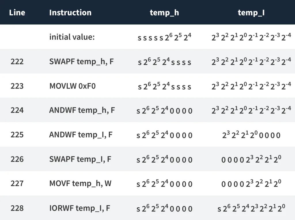
As you see after implementation of line 222 we will have the correct order of the bits in the ‘temp_h’ register, we just need to set the lower 4 bits to 0. We do this using lines 223 and 224. In line 225 we set the lower 4 bits of the ‘temp_l’ register to get rid of the fractional part.
Then we swap the ‘temp_l’ register to put the significant bits to their correct place. Now we have the upper 4 bits in the ‘temp_h’ register and the lower 4 bits in the ‘temp_l’ register. The only thing we need to do now is to join these registers using the IORWF instruction (lines 227, 228) - and viola! We now have the correct temperature value in the ‘temp_l’ register, and we didn’t use any shift instruction. But in fact we were lucky that we had to shift the byte by 4 bits, if this number was different we couldn’t use this trick.
Also, we saved the sign bit as well, so we can also indicate the negative temperature (but we won’t here).
Now we need to split the temperature into digits. As the home temperature normally has two digits and is positive we will split the value by dividing it by 10. For instance the temperature is 27 degrees.When we divide it by ten we will get the integer result 2 and the modulo 7. Thus we split 27 to 2 and 7 which we wanted to do.
Unfortunately, the PIC10F200 microcontroller doesn’t have an instruction to implement multiplication and division, so we need to invent the algorithm to do it. The simplest way of implementing the division is the consecutive subtraction while checking the result. Let me show you an example of the value 27 but first I’ll explain how the program works. To implement the division we need a special register which we call ‘tens’, and initially we should set it to 0 (line 230). Also, we will need to load the value 10 into the W register to perform the subtraction (line 231). In line 232, we start the division loop.
    CLRF tens   		 ;Clear 'tens' register
    MOVLW D'10'   		 ;Load 10 into the W register
DIVIDE   				 ;Start loop of the division operation
    SUBWF temp_l, F   	 ;Subtract W from 'temp_l'
    BTFSS STATUS, C   	 ;And check if Borrow status occurred
    GOTO END_SPLIT   	 ;If it was, then end operation
    INCF tens, F   	 ;Otherwise increment tens
    GOTO DIVIDE   		 ;And return to the 'DIVIDE' label
END_SPLIT
    ADDWF temp_l, F   	 ;Add W to 'temp_l'
    RETLW 0   			 ;And return from the subroutine
First, we subtract 10 from the ‘temp_l’ (line 233) and check if the borrow status occurred by checking if the bit C of the STATUS flag is 0 (line 234). If it occurred, which means that the ‘temp_l’ became negative, then we consider that the division is done and go to the ‘END_SPLIT’ label (line 235) which is located in line 238. To return the ‘temp_l’ to the last normal value we use another new instruction ADDWF (line 239), which is opposite to the SUBWF, and allows to add the File register to the W register and save the result either in the first one or in the second one depending on the second operand.
If the borrow status has not occurred, that means that the ‘temp_l’ is still positive, and we can subtract 10 again (line 237). But first we increment the ‘tens’ value to save the number of 10s that we have subtracted (line 236).
Let me show you now how this works on the example of 27:
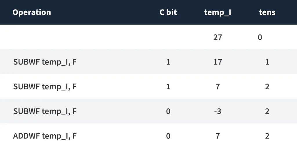
So we subtract the 10 from 27 till it becomes -3. In this case we don’t increment ‘tens’ anymore but add 10 to the ‘temp_l’ to return it to the last positive result.
That’s all about the ‘SPLIT_TEMP’ subroutine. As you see it’s quite short but has brought us a lot of new knowledge.
;------------Decode digit----------------------
DECODE_DIGIT
    MOVWF digit   		 ;Copy W into 'digit'
    MOVF digit, F   	 ;Check if 'digit' is 0
    BTFSC STATUS, Z   	 ;If yes, then return with the code
    RETLW B'00111111' 	 ;to display '0' digit
    DECFSZ digit, F   	 ;Decrement the 'digit' and check if it's 0
    GOTO $+2   		 ;If not, skip the next line
    RETLW B'00000110'   ;Otherwise return with the code of '1'
    DECFSZ digit, F   	 ;Decrement the 'digit' and check if it's 0
    GOTO $+2   		 ;If not, skip the next line
    RETLW B'01011011'   ;Otherwise return with the code of '2'
    DECFSZ digit, F   	 ;Decrement the 'digit' and check if it's 0
    GOTO $+2   		 ;If not, skip the next line
    RETLW B'01001111'   ;Otherwise return with the code of '3'
    DECFSZ digit, F   	 ;Decrement the 'digit' and check if it's 0
    GOTO $+2   		 ;If not, skip the next line
    RETLW B'01100110'   ;Otherwise return with the code of '4'
    DECFSZ digit, F   	 ;Decrement the 'digit' and check if it's 0
    GOTO $+2   		 ;If not, skip the next line
    RETLW B'01101101'   ;Otherwise return with the code of '5'
    DECFSZ digit, F   	 ;Decrement the 'digit' and check if it's 0
    GOTO $+2   		 ;If not, skip the next line
    RETLW B'01111101'   ;Otherwise return with the code of '6'
    DECFSZ digit, F   	 ;Decrement the 'digit' and check if it's 0
    GOTO $+2   		 ;If not, skip the next line
    RETLW B'00000111'   ;Otherwise return with the code of '7'
    DECFSZ digit, F   	 ;Decrement the 'digit' and check if it's 0
    GOTO $+2   		 ;If not, skip the next line
    RETLW B'01111111'   ;Otherwise return with the code of '8'
    DECFSZ digit, F   	 ;Decrement the 'digit' and check if it's 0
    GOTO $+2   		 ;If not, skip the next line
    RETLW B'01101111'   ;Otherwise return with the code of '9'
    RETLW 0x00   		 ;In any other case return 0
The next is the ‘DECODE_DIGIT’ subroutine (lines 242-274). It’s quite simple yet long. Firstly we load the ‘digit’ register from the W register (line 243). Then we check if the ‘digit’ register is 0 by calling the MOVF instruction (line 244) and checking the Z bit of the STATUS register (line 245). If the ‘digit’ was 0, then we return from the subroutine and load the value ‘0b00111111 ‘ into the W register (line 246). This value allows to show ‘0’ on the display (you can verify this using fig. 2). If ‘digit’ is not 0 then we decrement it and check if it becomes 0 (line 247). If yes, that means that it was initially 1 and thus we can return from the subroutine with the code ‘0b00000110’ (line 249) which allows us to display ‘1’ on the LED indicator. If the result is not 0 then we skip line 249 by calling GOTO $+2 (line 248) and get to line 250 where we decrement the ‘digit’ value again and check if the result is 0 now. If yes, then ‘digit’ was initially 2, and we return with the code corresponding to ‘2’ value. If not, we keep decrementing the digit till it becomes 0 and return the corresponding code. If for some reason ‘digit’ turned out to be higher than 9, then we finally get to line 274 where we return from the subroutine with W = 0, which means that no segment will be lit up.
;-------------Short delay subroutine--------------
SHORT_DELAY
    MOVWF i   		 ;Copy the value to the register i
SHORT_DELAY_LOOP     ;Start short delay loop
    DECFSZ i, F   	 ;Decrement i and check if it is not zero
    GOTO SHORT_DELAY_LOOP;If not, go to the SHORT_DELAY_LOOP label
    RETLW 0   		 ;Otherwise return from the subroutine
;-------------Long delay subroutine--------------
DELAY
	MOVWF i  		  ;Copy the value to the register i
	MOVWF j  		  ;Copy the value to the register j
    MOVWF k  		  ;Copy the value to the register k
DELAY_LOOP  		  ;Start delay loop
	DECFSZ i, F  	  ;Decrement i and check if it is not zero
	GOTO DELAY_LOOP   ;If not, then go to the DELAY_LOOP label
	DECFSZ j, F  	  ;Decrement j and check if it is not zero
	GOTO DELAY_LOOP   ;If not, then go to the DELAY_LOOP label
    DECFSZ k, F  	  ;Decrement k and check if it is not zero
	GOTO DELAY_LOOP   ;If not, then go to the DELAY_LOOP label
	RETLW 0  		  ;Otherwise return from the subroutine

    END
In lines 276-281 and 283-294 there are subroutines ‘SHORT_DELAY’ and ‘DELAY’ but, there is nothing interesting in them.
So that’s all I want to tell you about the program, I hope, now you understand it clearly, and that means that the time has come for the practical work. You can assemble the thermometer according to figure 10 but don’t connect the wires that come from DIO and CLK pins of the LCD display as they prevent the normal programming procedure (I think this happens because inside the programming process the TM1637 chip recognizes the Start condition and tries to set the ACK bit when nobody expects this). Then program the microcontroller and remove the wires ICSPDAT and ICSPCLK that come from the programmer to the microcontroller, as now they will prevent the normal operation of the TM1637 chip. Now you can connect the DIO and CLK wires and immediately see the temperature on the display. If you don’t then check the connection, as the device starts to work immediately and doesn’t need any further adjustment except those I’ve mentioned. If everything works good, touch the sensor with your finger and see how the temperature increases, now release the sensor and see how temperature slowly falls down. Everything works as expected!
Now I want to show you the real signals that I’ve obtained by means of the logic analyzer (figure 11). As you see, it can recognize the 1-wire protocol, and not only decode the bytes but also recognize the special states: Reset and present pulses, and commands, like “Skip ROM”. As you hopefully guessed, in figure 11 we see the reading of the temperature from the sensor.

In conclusion I’ll provide you with some traditional statistics. We’ve studied another popular interface - 1-wire and learnt how to build the digital thermometer based on the DS18B20 sensor that uses this interface. Also we’ve learnt 3 new instructions: SWAPF, IORWF, and ADDWF, so now we know 28 of 33. The program spends 208 words of the flash memory, so there is still space for some improvements.
As a home work, I’ll give you two tasks which are mutually exclusive:
- Convert the temperature into the Fahrenheit degrees and display three digits of it.
- Add the processing and display of negative temperatures in Centigrade.
The solution will be presented below but first try to find it by yourself, and after that, don’t be lazy to check my variant as I’m going to show you one more new instruction.
So, let me show you the part of the program that converts the temperature into the Fahrenheits degrees and displays it.
;Send second command and data to LED display
    CALL TW_START   	 ;Issue Start condition
    MOVLW 0xC0   		 ;Send address 0xC0 -
    CALL TW_WRITE_BYTE    ;The first address of the display
    MOVF temp_h, W   	 ;Load 'temp_h' into the 'DECODE_DIGIT'
    CALL DECODE_DIGIT    ;Get the display data
    CALL TW_WRITE_BYTE    ;Write the first digit to the display
    MOVF tens, W   	 ;Load 'tens' into the 'DECODE_DIGIT'
    CALL DECODE_DIGIT    ;Get the display data
    CALL TW_WRITE_BYTE    ;Write the second digit to the display
    MOVF temp_l, W   	 ;Load 'temp_l' into the 'DECODE_DIGIT'
    CALL DECODE_DIGIT    ;Get the display data
    CALL TW_WRITE_BYTE    ;Write the third digit to the display
    MOVLW B'01110001'
    CALL TW_WRITE_BYTE    ;Write 'F' at the fourth character
    CALL TW_STOP   	 ;Issue Stop condition
;------------Split temperature-----------------
SPLIT_TEMP
    MOVLW 3   			 ;Load 3 into the 'bit_count' to shift
    MOVWF bit_count   	 ;temperature at 3 bits to the right
SHIFT   				 ;Start of shifting loop
    RRF temp_l, F   	 ;Shift the 'temp_l' to the right
    BCF temp_l, 7   	 ;Clear the MSB of the 'temp_l'
    BTFSC temp_h, 0   	 ;Check if the LSB of the 'temp_h' is 1
    BSF temp_l, 7   	 ;If yes, then set the MSB of the 'temp_l'
    RRF temp_h, F   	 ;Then shift the 'temp_h' to the right
    DECFSZ bit_count, F    ;Decrement the 'bit_count', check if it's 0
    GOTO SHIFT   		 ;If not, return to the 'SHIFT' label

;Conversion to Fahrenheits
;Multiply by 9
    CLRF temp_h   		 ;Clear the 'temp_h' register
    MOVLW 8   			 ;Load 8 into 'bit_count' as we will add
    MOVWF bit_count   	 ;'temp_l' 8 more times to multiply it by 9
    MOVF temp_l, W   	 ;Copy the 'temp_l' into the W register
MULTIPLY_9   			 ;Start of multiplying loop
    ADDWF temp_l, F   	 ;Add W to the 'temp_l' and save in 'temp_l'
    BTFSC STATUS, C   	 ;Check if the C bit of the STATUS is set
    INCF temp_h, F   	 ;if yes, then increment the 'temp_h'
    DECFSZ bit_count, F    ;Decrement the 'bit_count', check if it's 0
    GOTO MULTIPLY_9   	 ;If not, return to the 'MULTIPLY_9' label

;Divide 16-bit value by 10
    CLRF tens   		 ;Clear 'tens' register
    MOVLW D'10'   		 ;Load 10 into the W register
DIVIDE_10_WORD   		 ;Start loop of the division operation
    SUBWF temp_l, F   	 ;Subtract W from 'temp_l'
    BTFSS STATUS, C   	 ;And check if Borrow status occurred
    GOTO CHECK_H   	 ;If it was, then check the upper byte
    INCF tens, F   	 ;Otherwise increment tens
    GOTO DIVIDE_10_WORD    ;And return to the 'DIVIDE_10_WORD' label
CHECK_H   				 ;Check the upper byte of the temperature
    MOVF temp_h, F   	 ;Check if the 'temp_h' register is 0
    BTFSC STATUS, Z
    GOTO SPLIT   		 ;If yes, then go the the 'SPLIT' label
    DECF temp_h, F   	 ;Otherwise decrement the 'temp_h'
    INCF tens, F   	 ;Increment the 'tens' value
    GOTO DIVIDE_10_WORD    ;And return to the 'DIVIDE_10_WORD' label

SPLIT   				 ;Split the 3-digits value
    MOVLW D'32'   		 ;Add 32 to the 'tens' according to
    ADDWF tens, W   	 ;the conversion formula
    MOVWF temp_l   	 ;Then copy the value to the 'temp_l'

    CLRF temp_h   		 ;Clear the 'temp_h' register
    MOVLW D'100'   	 ;Load 100 into the W register
DIVIDE_100   			 ;Start loop of the division operation
    SUBWF temp_l, F   	 ;Subtract W from 'temp_l'
    BTFSS STATUS, C   	 ;And check if Borrow status occurred
    GOTO END_SPLIT_100    ;If it was, then end operation
    INCF temp_h, F   	 ;Otherwise increment 'temp_h'
    GOTO DIVIDE_100   	 ;And return to the 'DIVIDE_100' label
END_SPLIT_100
    ADDWF temp_l, F   	 ;Add W to 'temp_l'

    CLRF tens   		 ;Clear 'tens' register
    MOVLW D'10'   		 ;Load 10 into the W register
DIVIDE_10   			 ;Start loop of the division operation
    SUBWF temp_l, F   	 ;Subtract W from 'temp_l'
    BTFSS STATUS, C   	 ;And check if Borrow status occurred
    GOTO END_SPLIT_10    ;If it was, then end operation
    INCF tens, F   	 ;Otherwise increment tens
    GOTO DIVIDE_10   	 ;And return to the 'DIVIDE_10' label
END_SPLIT_10
    ADDWF temp_l, F   	 ;Add W to 'temp_l'
    RETLW 0   			 ;And return from the subroutine
As you see, now we display three digits: first we send the ‘temp_h’ (lines 71-73) which now consists of the hundreds digit of temperatures. I could use the special register for it but I decided to use what we have. Next, we send the ‘tens’ (lines 74-76) which represents the tens of the temperature like in the previous program, and last we send the ‘temp_l’ (lines 77-79) which represents the units of the temperature. As the fourth character we send the ‘F’ letter (lines 81, 82) to indicate that we are showing the temperature in Fahrenheit.
The ‘SPLIT_TEMP’ subroutine (lines 222-290) becomes much more complicated and consists of some new things.
As you probably know (and if you don’t, no worries, I’ll provide you this information) to convert the temperature from Celsius to Fahrenheit you can use the following formula:

So we need to take the temperature in Centigrades, multiply it by 9, then divide by 5, and finally add 32. So a lot of actions are required. Moreover, if we multiply the temperature by 1.8 (9/5 = 1.8) then we will lose the accuracy, and some values can be missed. That’s why it’s better to have accuracy of at least 0.5 Centigrades. So we will shift the initial temperature reading not by 4 bits but by 3 bits, and that’s why the trick with nibble swapping won’t work, so we need to make real shifts. Let’s see how it works.
;------------Split temperature-----------------
SPLIT_TEMP
    MOVLW 3   			 ;Load 3 into the 'bit_count' to shift
    MOVWF bit_count   	 ;temperature at 3 bits to the right
SHIFT   				 ;Start of shifting loop
    RRF temp_l, F   	 ;Shift the 'temp_l' to the right
    BCF temp_l, 7   	 ;Clear the MSB of the 'temp_l'
    BTFSC temp_h, 0   	 ;Check if the LSB of the 'temp_h' is 1
    BSF temp_l, 7   	 ;If yes, then set the MSB of the 'temp_l'
    RRF temp_h, F   	 ;Then shift the 'temp_h' to the right
    DECFSZ bit_count, F    ;Decrement the 'bit_count', check if it's 0
    GOTO SHIFT   		 ;If not, return to the 'SHIFT' label
In lines 223-224 we load value ‘3’ into the ‘bit_count’ register as we want to shift at 3 bits.
Then we start the shifting loop with the ‘SHIFT’ label (line 225). First we need to shift the lower byte ‘temp_l’ to the right (line 226) and clear its MSB (line 227) in case it becomes ‘1’ after shifting through the Carry bit. Then we check the LSB of the higher byte ‘temp_h’ (line 228), and if it’s 1 then we set the MSB of the ‘temp_l’ to 1 (line 229). Lines 228, 229 implement transferring the bit from the higher byte to the lower one, and thus makes the 16-bit word shifting to the right. Then we shift the ‘temp_h’ to the right (line 230). We don’t worry about the MSB of the ‘temp_h’ as we will only need the result, saved in the ‘temp_l’ byte.
Finally, we check the ‘bit_count’ value and return to the ‘SHIFT’ label if it is 0 (lines 231, 232).
After implementing this part of the code the ‘temp_l’ will keep the value [26 25 24 23 22 21 20 2-1] so the LSB corresponds to 0.5 degrees Centigrade. Now we need to multiply this value by 9. There is no multiplication instruction in the PIC10F200 as well, so we need to make up the algorithm for it. There are two basic algorithms - “shift & add”, and “just add”. The first one has the defined number of iterations, it’s always the same as the bit depth of the numbers to multiply. The second one is simpler but can be longer because if we need to multiply X by Y we do (X + X + X + X…. + X) Y times. In our case Y is just 9, so we will use the second algorithm. Also, we should take care with the ‘Carry’ bit of the ‘STATUS’ register because while summing the ‘temp_l’ value, it may overflow, so we need to use the ‘temp_h’ to store the upper bits of the result, so this is going to be another 16-bit operation.
;Conversion to Fahrenheits
;Multiply by 9
    CLRF temp_h   		 ;Clear the 'temp_h' register
    MOVLW 8   			 ;Load 8 into 'bit_count' as we will add
    MOVWF bit_count   	 ;'temp_l' 8 more times to multiply it by 9
    MOVF temp_l, W   	 ;Copy the 'temp_l' into the W register
MULTIPLY_9   			 ;Start of multiplying loop
    ADDWF temp_l, F   	 ;Add W to the 'temp_l' and save in 'temp_l'
    BTFSC STATUS, C   	 ;Check if the C bit of the STATUS is set
    INCF temp_h, F   	 ;if yes, then increment the 'temp_h'
    DECFSZ bit_count, F    ;Decrement the 'bit_count', check if it's 0
    GOTO MULTIPLY_9   	 ;If not, return to the 'MULTIPLY_9' label
First, we clear the ‘temp_h’ register (line 236) because now we do care about its content. Then we load the value 8 into the ‘bit_count’ register (lines 237, 238). You may ask: why 8, and not 9? It’s simple. the ‘temp_l’ already has the X value, so we need to add 8 more X’s to get 9X. Then we copy the content of the ‘temp_l’ into the W register (line 239) and start the multiplication loop with the label ‘MULTIPLY_9’ (line 240). Inside this loop everything is quite simple. We sum the W register with the ‘temp_l’ register and save the result back in the ‘temp_l’ register (line 241). Then we check if the ‘C’ bit of the STATUS register is set, which means that byte overflow occurred (line 242). If it is set, then we increment the ‘temp_h’ register to save the lost bit in it (line 243). And finally we check the ‘bit_count’ and return to the ‘MULTIPLY’ label if it is not 0 (lines 244, 245).
After this part we have the 16-bit value of the temperature multiplied by 9 in registers ‘temp_h’ and ‘temp_l’. And according to the formula we now need to divide it by 5. There is one “but” though. As you remember, the LSB of the ‘temp_l’ before the multiplication represented 0.5 degrees, not 1 degree, that’s why the value seemed to be twice as big. So after multiplying by 9 the value looks like being multiplied by 18. To return it according to the formula, we need to divide it by 10, not by 5. After that, the LSB will represent 1 degree of Fahrenheit which we need.
;Divide 16-bit value by 10
    CLRF tens   		 ;Clear 'tens' register
    MOVLW D'10'   		 ;Load 10 into the W register
DIVIDE_10_WORD   		 ;Start loop of the division operation
    SUBWF temp_l, F   	 ;Subtract W from 'temp_l'
    BTFSS STATUS, C   	 ;And check if Borrow status occurred
    GOTO CHECK_H   	 ;If it was, then check the upper byte
    INCF tens, F   	 ;Otherwise increment tens
    GOTO DIVIDE_10_WORD    ;And return to the 'DIVIDE_10_WORD' label
CHECK_H   				 ;Check the upper byte of the temperature
    MOVF temp_h, F   	 ;Check if the 'temp_h' register is 0
    BTFSC STATUS, Z
    GOTO SPLIT   		 ;If yes, then go the the 'SPLIT' label
    DECF temp_h, F   	 ;Otherwise decrement the 'temp_h'
    INCF tens, F   	 ;Increment the 'tens' value
    GOTO DIVIDE_10_WORD    ;And return to the 'DIVIDE_10_WORD' label
OK, we already know how the division algorithm is implemented, but this time there will be two differences: we divide the 2-byte number, and we don’t care about the modulo. This algorithm is implemented in lines 248-262. The result of the division we’ll save into the ‘tens’ register, so we clear it initially (line 248). The difference from the division considered in the main part of the Tutorial is that if we get the ‘Borrow’ state (line 252) we go to the ‘CHECK_H’ label (line 253) which is located at lines 256-262. In this part we check if the ‘temp_h’ register is 0 (lines 257-258). If yes, that means that both ‘temp_l’ and ‘temp_h’ are empty and we can finish the division and go to the ‘SPLIT’ label. Otherwise, we need to decrement the ‘temp_h’ value (line 260), don’t forget to increment the ‘tens’ value (line 261) as we skipped this action by when we implemented the GOTO instruction in line 253, and return to the division loop (line 262).
SPLIT   				 ;Split the 3-digits value
    MOVLW D'32'   		 ;Add 32 to the 'tens' according to
    ADDWF tens, W   	 ;the conversion formula
    MOVWF temp_l   	 ;Then copy the value to the 'temp_l'

    CLRF temp_h   		 ;Clear the 'temp_h' register
    MOVLW D'100'   	 ;Load 100 into the W register
DIVIDE_100   			 ;Start loop of the division operation
    SUBWF temp_l, F   	 ;Subtract W from 'temp_l'
    BTFSS STATUS, C   	 ;And check if Borrow status occurred
    GOTO END_SPLIT_100    ;If it was, then end operation
    INCF temp_h, F   	 ;Otherwise increment 'temp_h'
    GOTO DIVIDE_100   	 ;And return to the 'DIVIDE_100' label
END_SPLIT_100
    ADDWF temp_l, F   	 ;Add W to 'temp_l'

    CLRF tens   		 ;Clear 'tens' register
    MOVLW D'10'   		 ;Load 10 into the W register
DIVIDE_10   			 ;Start loop of the division operation
    SUBWF temp_l, F   	 ;Subtract W from 'temp_l'
    BTFSS STATUS, C   	 ;And check if Borrow status occurred
    GOTO END_SPLIT_10    ;If it was, then end operation
    INCF tens, F   	 ;Otherwise increment tens
    GOTO DIVIDE_10   	 ;And return to the 'DIVIDE_10' label
END_SPLIT_10
    ADDWF temp_l, F   	 ;Add W to 'temp_l'
    RETLW 0   			 ;And return from the subroutine
After this part of the program we will have the T(C) * 9 / 5 value in the ‘tens’ register. Now we need to add 32 to it to get the correct temperature in Fahrenheit (lines 265, 266), then we copy the value to the ‘temp_l’ register (line 267). Now we have the correct value according to the formula in the ‘temp_l’ register, and we are ready to split it into digits. This time we'll split it by three digits: hundreds, tens, and units. To get the hundreds value we need to divide the ‘temp_l’ register by 100, which we do in lines 269-278. This part doesn’t have anything new, so I’ll skip its explanation. After it we will have the hundreds value in the ‘temp_h’ register, and the modulo in the ‘temp_l’ register. This modulo is definitely less than 100, so we can now split it as we did in the main part of the Tutorial by dividing the ‘temp_l’ by 10 (lines 280-289), and after that we’ll have three separated digits for hundreds, tens, and single units, and we can show them in the display (lines 68-82).
That’s all about this part of the homework. We’ve learnt how to implement some 16-bit operations, like shift, multiplication, and division. As you see, in assembly language things can be more complicated: if we were in C, we’d write just t = t * 9 / 5 + 32, here we spent 34 instructions to do this simple action.
Now let’s see how to display the negative temperature.
;Send second command and data to LED display
    CALL TW_START   	 ;Issue Start condition
    MOVLW 0xC0   		 ;Send address 0xC0 -
    CALL TW_WRITE_BYTE    ;The first addres of the display
    CLRW    			 ;Clear the W register
    BTFSC temp_h, 7   	 ;Check the Sign bit of the temp_h
    MOVLW B'01000000'    ;If it's 1 then display '-' sigh
    CALL TW_WRITE_BYTE    ;Write 'C' at the fourth character
    MOVF tens, W   	 ;Load 'tens' into the 'DECODE_DIGIT'
    CALL DECODE_DIGIT    ;Get the display data
    CALL TW_WRITE_BYTE    ;Write the first digit to the display
    MOVF temp_l, W   	 ;Load 'temp_l' into the 'DECODE_DIGIT'
    CALL DECODE_DIGIT    ;Get the display data
    CALL TW_WRITE_BYTE    ;Write the second digit to the display
    MOVLW B'01100011'
    CALL TW_WRITE_BYTE    ;Write digit sign as the third character
    CALL TW_STOP   	 ;Issue Stop condition
;------------Split temperature-----------------
SPLIT_TEMP
    SWAPF temp_h, F   	 ;Swap the nibbles of the 'temp_h'
    MOVLW 0xF0   		 ;Load the 0xF0 into the W register
    ANDWF temp_h, F   	 ;AND W and 'temp_h' to clear the lower 4 bits
    ANDWF temp_l, F   	 ;AND W and 'temp_h' to clear the lower 4 bits
    SWAPF temp_l, F   	 ;Swap the nibbles of the 'temp_l'
    MOVF temp_h, W   	 ;Copy the 'temp_h' into the W
    IORWF temp_l, F   	 ;OR between W and 'temp_l'

    BTFSS temp_l, 7   	 ;Check the 'sign' bit of the 'temp_l'
    GOTO SPLIT   		 ;If it is 0 then go to the 'SPLIT' label
    COMF temp_l, F   	 ;Otherwise invert the 'temp_l' values
    INCF temp_l, F   	 ;And add 1 to it

SPLIT
    CLRF tens   		 ;Clear 'tens' register
    MOVLW D'10'   		 ;Load 10 into the W register
DIVIDE   				 ;Start loop of the division operation
    SUBWF temp_l, F   	 ;Subtract W from 'temp_l'
    BTFSS STATUS, C   	 ;And check if Borrow status occurred
    GOTO END_SPLIT   	 ;If it was, then end operation
    INCF tens, F   	 ;Otherwise increment tens
    GOTO DIVIDE   		 ;And return to the 'DIVIDE' label
END_SPLIT
    ADDWF temp_l, F   	 ;Add W to 'temp_l'
    RETLW 0   		 ;And return from the subroutine
This time the changes are not that crucial. Let’s consider them.
In displaying part of the program we will display the ‘-’ sign at the first position if the temperature is negative, and leave it blank if temperature is positive. This is implemented in lines 71-73.
;Send second command and data to LED display
    CALL TW_START   	 ;Issue Start condition
    MOVLW 0xC0   		 ;Send address 0xC0 -
    CALL TW_WRITE_BYTE    ;The first addres of the display
    CLRW    			 ;Clear the W register
    BTFSC temp_h, 7   	 ;Check the Sign bit of the temp_h
    MOVLW B'01000000'    ;If it's 1 then display '-' sigh
    CALL TW_WRITE_BYTE    ;Write 'C' at the fourth character
First, we clear the W register by a new instruction CLRW. It’s the same as CLRF but clears the W register instead of File register. Then we check the MSB of the ‘temp_h’ register (line 72). Why do we do this? As follows from the first table, the MSB of the ‘temp_h’ consists of the ‘Sign’ bit. If this bit is 0 then the value is positive, and if it’s 1 then the value is negative. But why do we use ‘temp_h’ and not ‘temp_l’ which MSB also represents the ‘Sign’ bit? The thing is that by this moment we’ve already modified the ‘temp_l’ value to be positive in the ‘SPLIT_TEMP’ subroutine.
So we check the ‘Sign’ bit in the ‘temp_h’ register, and then if it’s 1, we modify the W register and load the value 0b01000000 into it which lights up segment G, indicating the ‘-’ sign.
    MOVF tens, W   	 ;Load 'tens' into the 'DECODE_DIGIT'
    CALL DECODE_DIGIT    ;Get the display data
    CALL TW_WRITE_BYTE    ;Write the first digit to the display
    MOVF temp_l, W   	 ;Load 'temp_l' into the 'DECODE_DIGIT'
    CALL DECODE_DIGIT    ;Get the display data
    CALL TW_WRITE_BYTE    ;Write the second digit to the display
    MOVLW B'01100011'
    CALL TW_WRITE_BYTE    ;Write digit sign as the third character
    CALL TW_STOP   	 ;Issue Stop condition
Then we display the tens (lines 75-77) and single units (lines 78-80) of the temperature, and finally we display the ° character (lines 81-82).
Now let’s see what changes there are in the ‘SPLIT_TEMP’ subroutine. I added only a few new lines: 232-237. In line 232 we check the ‘Sign’ bit of the ‘temp_l’ as it’s still valid. If it’s not 1, then we go to the ‘SPLIT’ label (line 233) where we divide the ‘temp_l’ value by 10 as we did in the initial program. If the ‘Sign’ bit is 1, we need to convert the temperature into the positive.
    BTFSS temp_l, 7   	 ;Check the 'sign' bit of the 'temp_l'
    GOTO SPLIT   		 ;If it is 0 then go to the 'SPLIT' label
There is a simple equation that works for this case:

So to convert the value into positive (and vice versa) we need to implement the NOT operation to the initial value (this will toggle all the bits of the value), and add 1 to the result.
Let me show how this works on the example of the same value -27.
-27 in binary is 0b11100101. When we apply the NOT operation to it, we get 0b00011010. Finally, we add 1 to this value and get 0b00011011. When we convert this value into the decimal form we will get 27, which we need.
Earlier we used the XOR operation to toggle the bits, but there is a special instruction to do this: COMF (Complement F). It has two operands: first is the register to be complemented, and second is F or W to indicate where to save the result. In this case “complement” means that if we add the initial value and the complementary one, you will get the value 0b11111111.
    COMF temp_l, F   	 ;Otherwise invert the 'temp_l' values
    INCF temp_l, F   	 ;And add 1 to it
So we apply this instruction to the ‘temp_l’ register (line 234) and add 1 to the result (line 235) to convert the temperature to the positive value. And that’s it, now we are good to split it as usual.
And that’s all about the second part of the homework. It’s simpler than the first one and doesn’t contain anything you couldn’t do by yourself even not knowing the new instructions.
As an updated conclusion, I want to note that we learned 2 more instructions: CLRW and COMF and now we know 30 of 33 (almost all of them). Also, we learnt how the most widespread arithmetical operations are implemented in the Assembler language!

Authored By
Sergey Sokol
I was born, raised, and currently live in Ukraine. I’m fond of different types of electronics and backpacking but these things have been set aside with the war that has been thrust on my country, my people, and my family. Through these trials, if you could help support me financially, I would appreciate any help that could be sent via Paypal to sokolsp@gmail.com

Related Tutorials
")
Related EE FAQs
 work?")
How do Analog to Digital Converters (ADCs) work?

Answered by Uma Bharathi D

What is the difference between sonar and ultrasonic sensors?

Answered by Susie Maestre

What's the difference between a regular relay and a power relay?

Answered by Jayesh Upadhyay

What is a PWM signal?
Answered by Jayesh Upadhyay

How do Hall Effect sensors work?
Answered by Jayesh Upadhyay
Explore CircuitBread
- 224 Tutorials
- 9 Textbooks
- 12 Study Guides
- 31 Tools
- 102 EE FAQs
- 295 Equations Library
- 205 Reference Materials
- 91 Glossary of Terms
Friends of CircuitBread
-

Browse Parts by Product
-

Power Supply Related Technical Resources + 1 Perk
-

Free eBook & Resource Library + 1 Perk


Get the latest tools and tutorials, fresh from the toaster.


