Half-Wave Rectifier in a Power Supply
Published
In our previous topics about diodes, we’ve learned about the pn junction, and how a diode works in forward bias and reverse bias. We have also discussed LEDs, which is a special-purpose diode, and have learned its operation and different applications. This time, we’re going to discuss another application of a diode which is really common to all electronic systems, the rectifier, specifically, the half wave rectifier in this case.
Rectifiers are circuits that convert an AC voltage into a DC voltage. Basically, they are always present in DC power supplies that operate from an AC voltage source. The ability of a diode to allow current to flow in one direction and block it in the other direction makes them very useful in rectifier circuits. When a diode is used in the rectification process, it is typically referred to as a rectifier.
BASIC DC POWER SUPPLY
DC power supplies are absolutely necessary in every electronic system since all active electronic devices require a DC voltage source to operate. In order to understand the function of a rectifier in a power supply, we should at least know the components and the operation of a basic DC power supply. From a higher level, the components of a DC power supply are the transformer, the rectifier, filter, regulator, and finally, the load. We’ll go over those briefly and then dive deeper into the rectifier portion.

Transformer
Most of the time, electronic devices require a lesser voltage level than the AC voltage level available at wall outlets. That is why in basic DC power supplies (linear regulated types) the first component that you will see is a transformer. The transformer allows the AC voltage source to be stepped down closer to the voltage level that you need and it also isolates the AC source electrically from the rectifier which is the component next to the transformer. The secondary voltage of a transformer depends on the turns ratio. But in reality, when you purchase a transformer, it’s not specified based on the turns ratio but on the secondary, or “output”
voltage.
Rectifier
The rectifier, which we will discuss more later, converts the AC voltage across the secondary side of the transformer into a pulsating DC voltage. It could be a half-wave or full-wave rectifier type, but in this tutorial we will just focus on the half-wave type.
Filter
The pulsing output of the rectifier is not good enough to be used in electronic devices. That’s why, next to the rectifier, a filter is necessary in order to produce a smooth DC voltage. The filter can be a single electrolytic capacitor or a combination of electrolytic and ceramic capacitors.
Regulator
Although the output of the filter is now smoother, if there are changes in the input voltage or in the load, the output DC voltage of the power supply will be affected. To avoid this, a regulator is used after the filter. The regulator regulates the voltage so that we could have a constant DC voltage across the load. Regulators can be a single semiconductor device like a Zener diode or could be more complicated integrated circuits, typically a trade-off between ease and cost versus efficiency.
HALF-WAVE RECTIFICATION

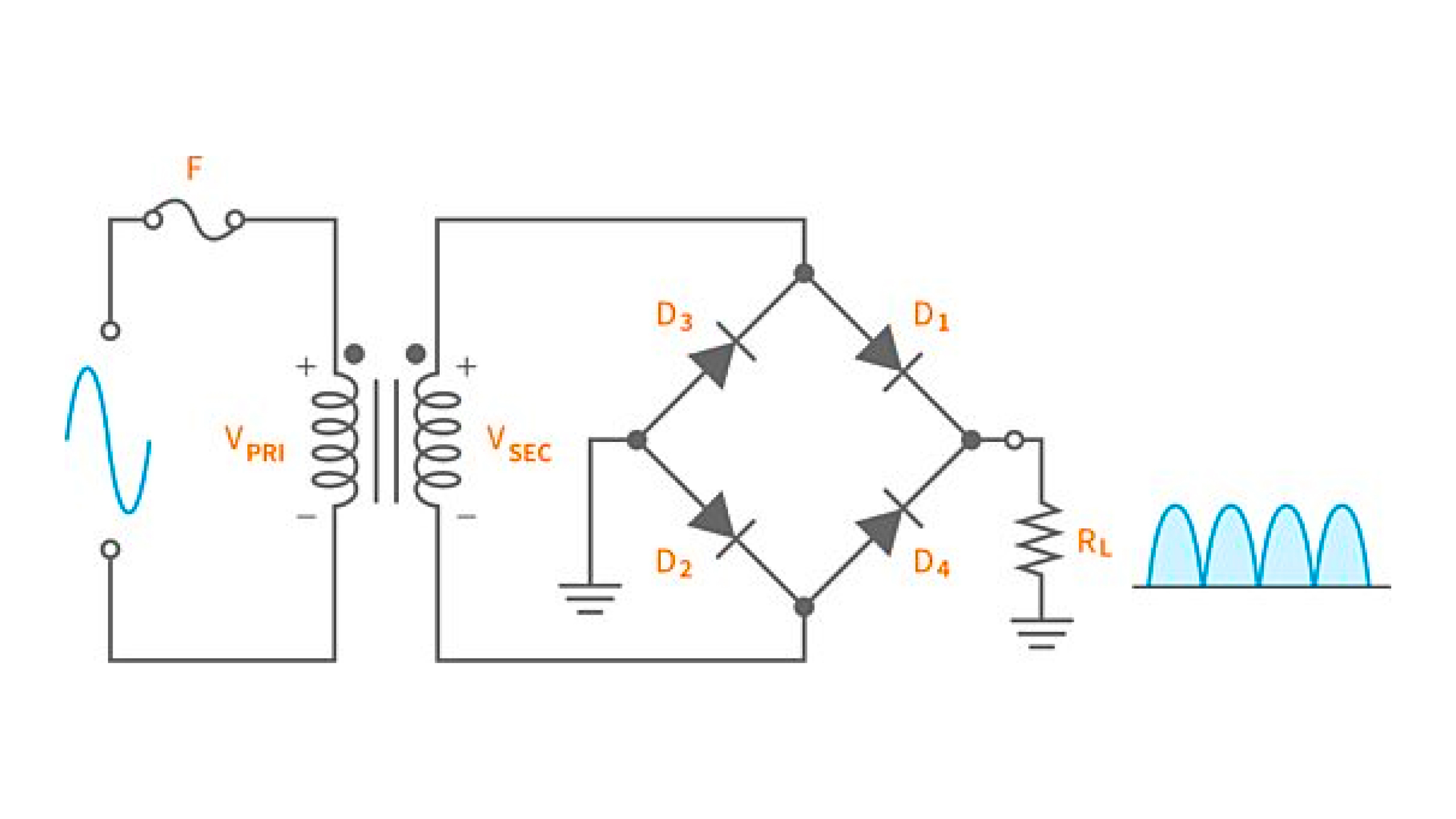
Now, focusing on the rectifier, as mentioned earlier, rectifiers could be half-wave or full-wave, but for now, we’re just going to discuss the half-wave rectifier. The image above shows a typical application circuit of a half-wave rectifier. From a 120 volts AC 60Hz wall outlet, there’s a fuse, F1, for protection and a transformer to step down the AC voltage into the desired voltage. The output voltage across the secondary is lower but its frequency is still 60Hz, which means that the voltage will change from positive to negative and negative to positive 60 times per second. Now let’s see what happens during one cycle of the AC voltage in a half-wave rectifier.

At this time we’re just going to treat the diode as ideal. During the positive half-cycle, the diode is forward-biased and allows current through the load which produces an output voltage across the load. Since the diode is considered to be ideal (acts just like a closed switch), the output voltage across the load looks like the positive half of the input AC voltage.

Half-wave rectifiers only use one diode to convert the AC voltage into a DC voltage. So when the voltage changes from positive to negative half-cycle, the diode is reverse-biased and doesn’t allow current to pass. In this case, during the negative half-cycle, there’s no current that can pass through the load so the voltage across it is zero.

In half-wave rectification, only the positive half-cycle of the input AC voltage is converted into a DC voltage. The result across the load is pulsating DC voltage with a 60Hz frequency.

Effect of the Barrier Potential on the Half-Wave Rectifier Output
So that’s how a half-wave rectifier works when the diode is considered to be ideal. In reality, the barrier potential of the diode affects the output of the half-wave rectifier. Because of the barrier potential, the diode is still open when the input voltage is less than the barrier potential level, so the width of the wave is slightly less than you’d expect in ideal conditions. Also, if you compare the graph of the input and output, you’ll notice an offset and the peak value of the output voltage is 0.7V less than the peak value of the input voltage, if the diode is silicon.

RMS, Peak, and Average Value
AC voltages can be specified in terms of its peak or rms (root-mean-square) value. However, the AC voltage from the wall outlet is in rms as well as the secondary voltage of the transformer. To calculate the output voltage of a half-wave rectifier, we need to calculate first the peak value of the transformer secondary voltage by multiplying the rms value of its voltage by 1.414. Then after that, subtract the barrier potential, which is usually 0.7V from the peak value of the secondary voltage.
The result you will get is the voltage across the load at its peak. The average or the DC voltage across the load, which you will see if you measure it using a DC voltmeter, is determined by multiplying the peak value of the load voltage by 0.318. We’re not going to get into the math as to why we use 1.414 or .318 in these cases but I do need to say that these numbers are only applicable in these cases with sinusoidal waves.
Peak Inverse Voltage
When using diodes in a rectifier circuit, another important thing to consider is its peak inverse voltage (PIV) rating, also known as peak reverse voltage(PRV). During half-cycles where the rectifier diode is reverse-biased, the PIV is the maximum reverse voltage that the diode will see or else it will be damaged. In a half-wave rectifier circuit, the PIV is equal to the peak value of input voltage applied or the secondary voltage of the transformer. But it’s recommended to use a diode rated at least 20% higher than the PIV. You can check the datasheet to see a diode’s PIV rating.

Advantages and Disadvantages
A half-wave rectifier is cheap and easy to build. However, it is rarely used due to its disadvantages. First, its efficiency is low. Only 40.6% of the AC power gets converted to DC power available to the load so there’s a lot of power wasted. Second, since the efficiency of a half-wave rectifier is low, it is expected that its ripple factor is high. The pulsing portion of the output of a rectifier are called ripples. Ideally, there shouldn’t be ripples at the output of a rectifier as we want our DC voltage to be smooth. However, the ripple factor of a half-wave rectifier is very high which indicates poor AC to DC conversion. Another disadvantage of using a half-wave rectifier is its low transformer utilization factor (TUF). TUF in a half-wave rectifier circuit is only 0.287, out of an ideal value of 1, which shows that the transformer is not even close to fully utilized.
Summary
In this tutorial, we’ve discussed rectifiers and its two types. We've also learned about the function of a rectifier in a basic DC power supply and have discussed the operation of a half-wave rectifier. In our next tutorial, we’re going to have a demonstration about a basic DC power supply with a half-wave rectifier. If you have any questions, leave it in the comments below. See you in our next tutorial!

Get the latest tools and tutorials, fresh from the toaster.

