How RGB LEDs work and how to control color
Published
We've discussed a lot about LEDs like how it works in a semiconductor level, its pros and cons, and how an individual LED can be dimmed through constant current reduction (CCR) or pulse width modulation (PWM) dimming. In this tutorial, we’re going to discuss about RGB LEDs and how to use them to produce different colors.
What is an RGB LED and how does it work?
An RGB LED is basically an LED package that can produce almost any color. It can be used in different applications such as outdoor decoration lighting, stage lighting designs, home decoration lighting, LED matrix display, and more.
RGB LEDs have three internal LEDs (Red, Green, and Blue) that can be combined to produce almost any color output. In order to produce different kinds of colors, we need to set the intensity of each internal LED and combine the three color outputs. In this tutorial, we are going to use PWM to adjust the intensity of the red, green, and blue LEDs individually and the trick here is that our eyes will see the combination of the colors, instead of the individual colors because the LEDs are very close to each other inside.
RGB LED Types and Structure
As mentioned earlier, RGB LEDs have three LEDs inside them and usually, these three internal LEDs share either a common anode or a common cathode especially in a through-hole package. So basically, we can categorize RGB LEDs as either common anode or common cathode type just like in seven segment displays.
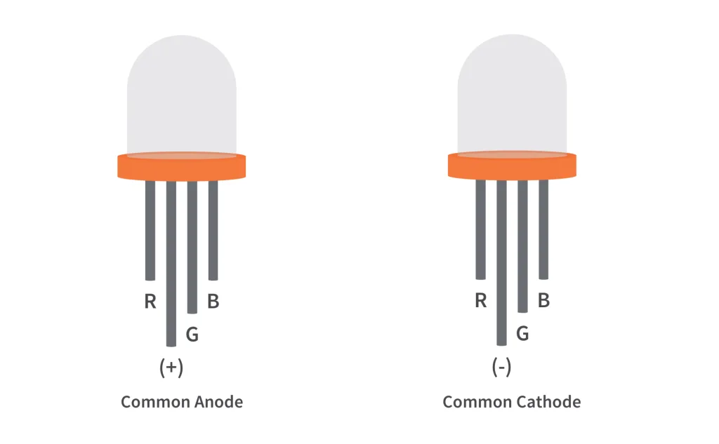
When you look at an RGB LED, you'll see that it has four leads. If you face it so that its longest lead is second from the left, the leads should be in the following order: red, anode or cathode, green, and blue.
Common Anode RGB LED
In a common anode RGB LED, the anode of the internal LEDs are all connected to the external anode lead. To control each color, you need to apply a LOW signal or ground to the red, green, and blue leads and connect the anode lead to the positive terminal of the power supply.

Common Cathode RGB LED
In a common cathode RGB LED, the cathode of the internal LEDs are all connected to the external cathode lead. To control each color, you need to apply a HIGH signal or VCC to the red, green, and blue leads and connect the anode lead to the negative terminal of the power supply.

Setting the color of an RGB LED using an Arduino Uno
In order to get the color that we want from an RGB LED, we need to set the intensity of each internal LED. To do this, we can either use constant current reduction (CCR) or pulse width modulation (PWM). But in this example, we're going to use PWM since we are using an Arduino Uno to set the color of the RGB LED.
Parts Used:
1. Arduino Uno
2. Common Cathode RGB LED
3. 3 x 100Ω Resistors
4. 3 x 1kΩ Potentiometers/Trimmers
5. Jumper Wires
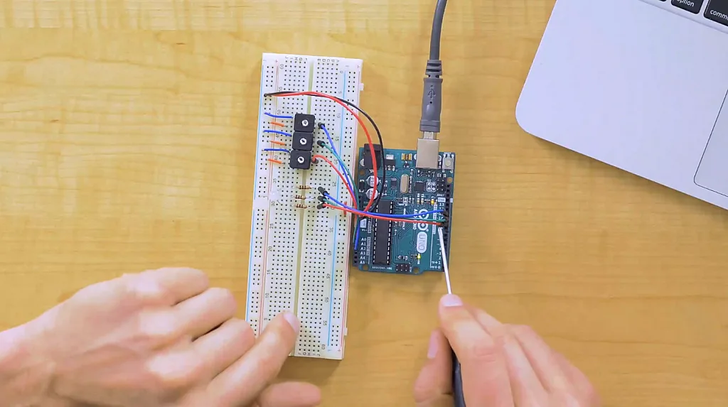
The setup is very easy. We have here a common cathode RGB LED, an Arduino Uno board, 3 potentiometers/trimmers, and 3 resistors. They're all connected through the jumper wires that we have. Basically, what happens here is that we have 3 potentiometers/trimmers connected to the A0, A1, and A2 ADC channels of the Arduino Uno. The ADC of the Arduino Uno reads the analog voltage across the wiper terminal of the potentiometers/trimmers and based on that voltage, the Arduino Uno adjusts the duty cycle of the PWM signals generated at the PWM pins D9, D10, and D11. As you can see in the image above, the D9 pin controls the intensity of the red LED of the RGB LED. The D10 pin controls the intensity of the green LED and D11 controls the intensity of the blue LED. The cathode pin of the RGB LED is connected to the GND pin of the Arduino Uno.
Note: In this example, we just used the same resistance value for the RGB LED series resistors. But if you have access to the datasheet of the RGB LED that you're using, check the forward voltages of internal LEDs and from that, you can calculate the right resistance of the resistors that you're going to use. That way, you can have a balance between the brightness of the internal LEDs.
Schematic Diagram
We have two schematic diagrams here, one is for the common anode wiring and the other one is for the common cathode. In our example, we are using the wiring for the common cathode RGB LED. But they're almost the same. The only difference is that the second lead of the RGB LED from the left is connected to the 5V pin of the Arduino Uno for the common anode while for the common cathode, the second lead is connected to GND.


Note: You need to change some parts of the code/sketch below if you're using a common anode RGB LED.
Arduino Code/Sketch
Upload this code/sketch to your Arduino Uno board through the Arduino IDE:
int RGBLED_RedPin = 9;
int RGBLED_GreenPin = 10;
int RGBLED_BluePin = 11;
int Previous_PWMValue_RedPin = 0;
int Threshold_PWMValue_RedPin = 0;
int Previous_PWMValue_GreenPin = 0;
int Threshold_PWMValue_GreenPin = 0;
int Previous_PWMValue_BluePin = 0;
int Threshold_PWMValue_BluePin = 0;

void setup()
{ Serial.begin(9600); // initialize serial communications at 9600 bps
  pinMode(RGBLED_RedPin, OUTPUT);
 pinMode(RGBLED_GreenPin, OUTPUT);
 pinMode(RGBLED_BluePin, OUTPUT);
}

void loop()
{  int Pot_RedPin = analogRead(A0);
 int PWMValue_RedPin = Pot_RedPin/4;
 int Pot_GreenPin = analogRead(A1);
 int PWMValue_GreenPin = Pot_GreenPin/4;
 int Pot_BluePin = analogRead(A2);
 int PWMValue_BluePin = Pot_BluePin/4;

 //Use this code for RGB LED COMMON CATHODE and comment the code for COMMON ANODE
 analogWrite(RGBLED_RedPin, PWMValue_RedPin);
 analogWrite(RGBLED_GreenPin, PWMValue_GreenPin);
 analogWrite(RGBLED_BluePin, PWMValue_BluePin);

 //Use this code for RGB LED COMMON ANODE and comment the code for COMMON CATHODE
 /*
 analogWrite(RGBLED_RedPin, 255-PWMValue_RedPin);
 analogWrite(RGBLED_GreenPin, 255-PWMValue_GreenPin);
 analogWrite(RGBLED_BluePin, 255-PWMValue_BluePin);
 */

 //This section is for serial printing the RGB decimal values.
 //Sometimes you get unstable output due to jumper wires not properly connected, poor quality breadboard, or poor quality potentiometers.
 Threshold_PWMValue_RedPin = abs(Pot_RedPin - Previous_PWMValue_RedPin);
 Threshold_PWMValue_GreenPin = abs(Pot_GreenPin - Previous_PWMValue_GreenPin);
 Threshold_PWMValue_BluePin = abs(Pot_BluePin - Previous_PWMValue_BluePin);
 if (Threshold_PWMValue_RedPin >= 10 || Threshold_PWMValue_GreenPin >= 10 || Threshold_PWMValue_BluePin >= 10)

 Serial.print("RGB (");
 Serial.print(PWMValue_RedPin);
 Serial.print(", ");
 Serial.print(PWMValue_GreenPin);
 Serial.print(", ");
 Serial.print(PWMValue_BluePin);
 Serial.println(") ");
 Previous_PWMValue_RedPin = Pot_RedPin;
 Previous_PWMValue_GreenPin = Pot_GreenPin;
 Previous_PWMValue_BluePin = Pot_BluePin;
 //This section is for serial printing the RGB decimal values.
 //Sometimes you get unstable output due to jumper wires not properly connected, poor quality breadboard, or poor quality potentiometers.

 delay(2);
}
The code here is very easy to understand. What it does is that it simply programs the Arduino Uno to read the voltage across the wiper terminal of the potentiometers or trimmers using the ADC peripheral and based on that voltage, the Arduino Uno adjusts the duty cycle of the PWM signals.
int RGBLED_RedPin = 9;
int RGBLED_GreenPin = 10;
int RGBLED_BluePin = 11pinMode(RGBLED_RedPin, OUTPUT);
pinMode(RGBLED_GreenPin, OUTPUT);
pinMode(RGBLED_BluePin, OUTPUT);
These lines configure the digital pins D9, D10, and D11 to be the PWM output pins.
int Pot_RedPin = analogRead(A0);
int PWMValue_RedPin = Pot_RedPin/4;
int Pot_GreenPin = analogRead(A1);
int PWMValue_GreenPin = Pot_GreenPin/4;
int Pot_BluePin = analogRead(A2);
int PWMValue_BluePin = Pot_BluePin/4;
This part of the code tells the Arduino Uno to read the voltage across the wiper terminal of the potentiometers/trimmers through channels A0, A1, and A2. Then it converts the values into a (0-255) range since the ADC uses 10-bit resolution which ranges from (0-1023) but the PWM function of the Arduino Uno uses a (0-255) range.
analogWrite(RGBLED_RedPin, PWMValue_RedPin);
analogWrite(RGBLED_GreenPin, PWMValue_GreenPin);
analogWrite(RGBLED_BluePin, PWMValue_BluePin);
These lines program the Arduino Uno to adjust the duty cycle of the PWM signals based on the voltages across the ADC channels.
The other lines in the code are for monitoring purposes. It allows you to monitor the RGB decimal value or the duty cycle of PWM signals through the serial monitor of the Arduino IDE.
Note: If you're using a common anode RGB LED, please read the comments inside the code. You need to comment out some code lines for the common cathode RGB LED and uncomment the code lines written for the common anode.
Summary
So RGB LEDs are really simple! They're just three LEDs that share a common anode or a common cathode and to set their color, you just need to adjust the intensity of each LEDs inside them. With the code above, you can experiment or try to use RGB LEDs in whatever projects that you want to do. If you’ve found this RGB LED tutorial interesting or helpful, give it a like and if you have any questions, leave it in the comments below. For more tutorials about technology and electronics, please sign up for our newsletter!

Authored By
JB Magoncia
JB is an Electronics Engineer who is interested in audio, embedded systems, and PCB design. He is one of CircuitBread Engineers. JB is also a musician who mainly plays piano/keyboard but can also play bass, guitar, and drums. He currently lives in Cagayan de Oro, Philippines.

Related Tutorials

Related EE FAQs

What's the difference between a regular relay and a power relay?

Answered by Jayesh Upadhyay

What is a PWM signal?
Answered by Jayesh Upadhyay

What are the Forward Voltages of Different LEDs?

Answered by Gary Crowell
?")
How do I test LEDs with Digital Multimeters (DMMs)?
Answered by Gary Crowell

How do I choose the correct resistor for my LED?
Answered by Gary Crowell
Explore CircuitBread
- 224 Tutorials
- 9 Textbooks
- 12 Study Guides
- 31 Tools
- 102 EE FAQs
- 295 Equations Library
- 205 Reference Materials
- 91 Glossary of Terms
Friends of CircuitBread


Get the latest tools and tutorials, fresh from the toaster.


