How to make a 360 degree Continuous Rotation Servo Motor?
Published
TRANSCRIPT
We are going to take a regular servo and convert it into a continuous rotation servo. You may see a lot of tutorials like this on YouTube and a couple of them are really good and a couple of them are terrible. I also want to go over exactly what the differences and some of the styles and explain why you're doing the things that you're doing. Not every servo is the same and not every person has the same tools and depending on the tools that you have on hand you can make you approach this differently. So we're going try and make it a little bit more vague while also still being very specific on exactly how to do it.

The first thing that I want to go over is that we are going to make this a continuous rotation servo — meaning that we will still be able to control the speed, and that we are still going to be able to control the rotation based off of a typical input. Now, I have seen a lot of people that'll take this and they'll basically just turn it into a geared DC motor which is totally fine. But, that's not what we're doing here. If you want a geared DC motor, you can follow a lot of these steps, but the difference is the control wires can just be chopped and soldered directly onto the motor. But that's not what we're going to be doing. With that, let's talk a little bit about the two overarching steps that you need to do this.
First, in a servo there is a mechanical stop. Something that makes them so they can't go more than a certain amount of distance. We need to overcome that issue. And the way these know their position is that there's a potentiometer that moves and changes the value of that potentiometer. In the servo, there's a small circuit board that says, “The potentiometer is giving me this reading so I know that I'm in this position." So we are going to have to bypass that potentiometer in one of two ways - we'll show one way but we'll discuss another way and then also make sure that the potentiometer isn't causing any issues as we completely rotate.
Again, servos are pretty cool because they are a feedback loop where it goes to a certain point and creates a voltage divider on the potentiometer. Then the circuit says, "Alright, we're in the right position." Then you send it another message and it says, “Oh, I'm supposed to be over here now”, and then it moves and says that it's in another spot and the potentiometer says, “Okay, now you're in the right position”. But when we're doing a continuous rotation, we basically want it so that the potentiometer is either completely out of the circuit or is giving bad information and that is where we have to trick it. Let's get right into it and start taking this apart and show the different steps.
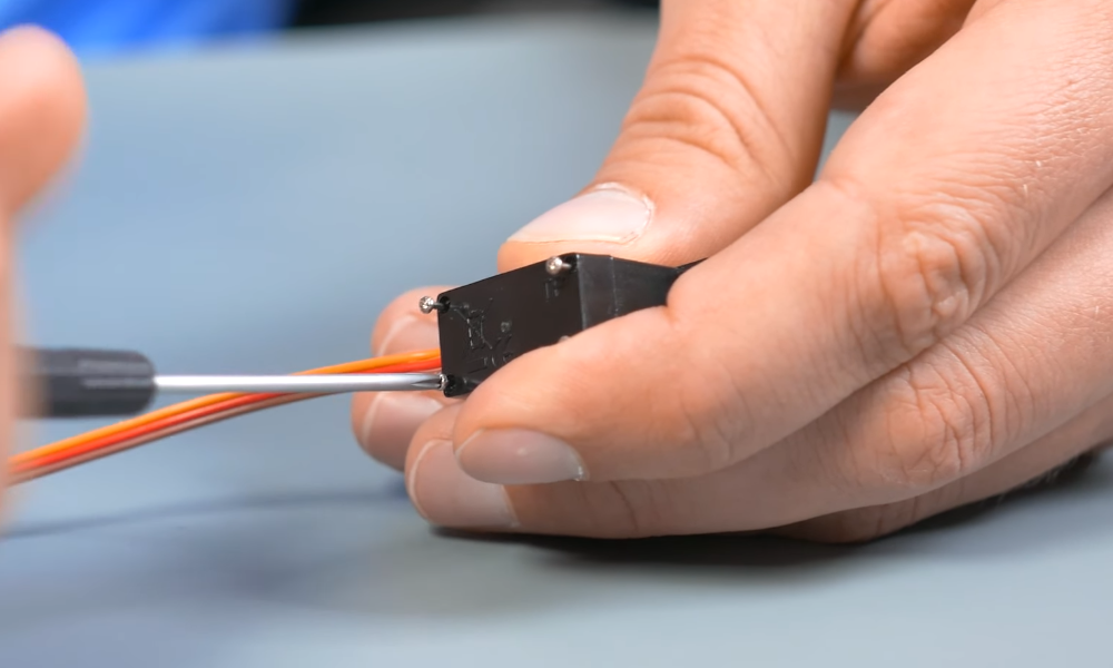
The step is to remove the screws on the back. As you remove them, don't try and pull the back off quite yet because we need to do one more thing before we pull everything apart. As we also do this, you pull the top screws out and it pops the bottom off. But it also allows us to take off the top.

Now that those are loose, let's grab an X-Acto knife. This isn't actually completely necessary but even if it's not completely necessary, it's kind of nice to just cut the paper at the seam so it looks nicer. Honestly, for me, it's twofold. One, it makes it so this comes apart a little bit easier and then don't have to worry about other issues. Two, it's a quick way for me to know which of my servos I've converted and which ones I haven't, even though I guess you could just write on it with a sharpie or whatever.
All right! So now it is coming apart. Let's pull this bottom portion off and look in there really quick.

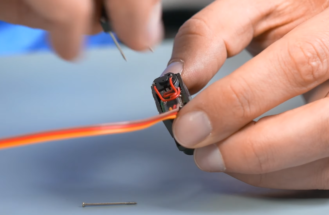
We've got the motor now and this is what runs down and turns the gears. But then, this is controlled by a little control board and that board is what's talking to the potentiometer which is right behind it that is trying to say, “Hey, where am I right now? And where do I need to be?" What we're going to have to do is we're gonna have to make some modifications to that board to change the logic so that it is getting one signal despite the fact there is actually another signal being produced by the potentiometer. Let's come back to that...
On this other side is where we see the different gears, and here, we need to worry about the physical aspects.

From this view you can see that the motor is turning and drives quite a few gears while also changing the potentiometer value.

As it turns, it's changing the signal and that is being turned by a top piece which you need to take off without breaking things. As you can see there is a flat piece that turns the potentiometer.
We're gonna have to make some modifications to this so that 1) it doesn't actually turn the potentiometer, and 2) gets rid of the stopper that jams into things and make it so you can't turn more than a little bit more than 180 degrees.

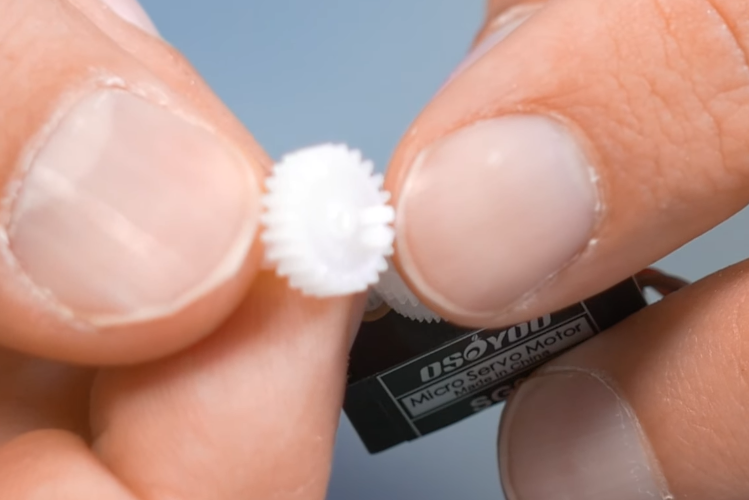
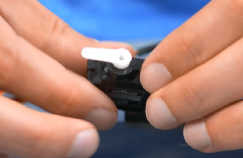
Now that we've discussed the internal operations, we need to take care of the physical pieces that restrict the movement. If you're turning this into a DC geared motor or a continuous rotation servo you're going to need to do this or else it's going to be jammed onto the potentiometer and the internal limits of the potentiometer are going to stop it. First things first, try and cut this stopper piece of plastic without cutting your fingers too severely. It doesn't have to be perfect but if you get it nice and flat then you know that that's not going to catch on anything and it's going to rotate nice and smoothly. So that's the first thing.

Second thing is we want to drill the portion out that fits tightly onto the motor output. To do this, I use a cordless drill. I found it's easier to first drill through and get the spot that catches on the end and then also go back with a slightly bigger drill bit to and get it a little bit wider.
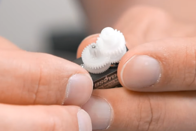
Now we are done with our drill. Now, you should see that it's completely flat right where the stopper was and that you've made the hole just slightly bigger. It should be able to fit right back on the shaft and spin freely even once the top is placed back on.
The way we are going to be faking out the potentiometer is we're going to just be bypassing it completely. Other people, using other methods out there, basically use a special device which we don't have. Which is why we're not doing it that way.
If you vary from this method slightly and are going to be still using the potentiometer and just locking it in place you'd probably want to take off all of these gears and glue it in place.

As we are not glueing the potentiometer in place, we're simply going to cut it out of the circuit. Go back to the logic side and find something tiny to cram in there, like a set of tweezers.

Breaking the physical connections can be difficult as you are bending and/or cutting leads. The most important part is that the potentiometer wires come off. There are three little spots and those are the three outputs from the potentiometer that I'm going to physically pull out. I'll also sometimes cover the bare pieces of metal with a small piece of electrical tape just to reduce the chance of making contact with something unintentionally.

If you have really thin snippers or clippers or something that you can get down there, that's great. I don't and so I actually use forceps to twist and break the wire. It is a bit ugly and it works extremely well sometimes and other times not very well. But it's a lot better than trying to get in there with something else to cut it. So you can just grab the wire, wiggle back and forth until it breaks.
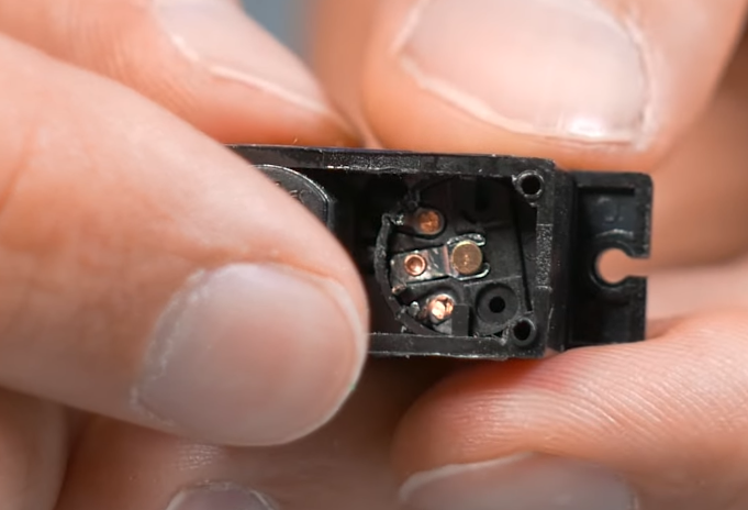
Now that you can see all three leads are broken, this is where you should cover things up with a piece of electrical tape.

If we were still using the potentiometer, and if you had something that was able to center the servo and make it so the potentiometer is perfectly centered, and then glue it in place, we would not be breaking this connection. However, I happen to have a couple of 0603 resistors on hand that I can put in as a voltage divider but you can use any type of resistor that will fit in the chassis of the servomotor. Even though I didn't use precision resistors in the video, they're close enough. If you have precision resistors, so that's even better. If you have some through-hole resistors, that will also work if they fit.

The only problem is they're pretty small because we're going create a perfect voltage divider across the center point. This makes the center point at exactly half the incoming voltage. Now we break out the soldering tools.
At this point, you need to solder the two resistors on. Do need to do it very carefully and hopefully you're better solderer than I am. I know that Sergey can do things that I can't do with my microscope and he can do them just his eyeballs. Which is very impressive. Hopefully you're impressive like he is and not half-blind like I am.
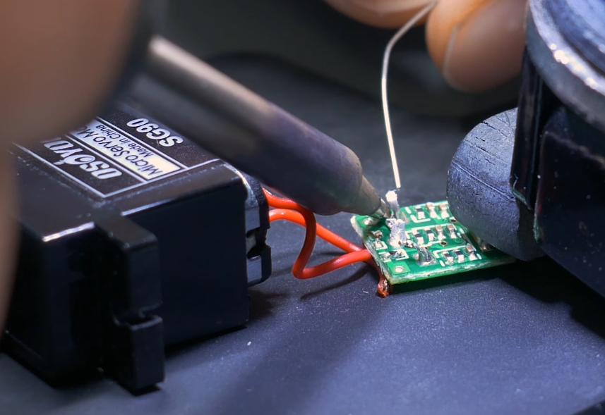
As we solder these in place, make sure you aren't unintentionally shorting out with something else. Also look for any damage that might have been done.
The main point of this is to make sure that the input to the driver thinks that it's always in the middle and so when you send it a signal to say, “hey, go to this direction”, it's going to keep on going until you tell it to stop because it's never gonna receive the feedback signal that it's actually reached its destination.

Now we've got a 2.2Kohm resistor and series with another 2.2Kohm resistor and that's because I measured this and the potentiometer seemed to be go, seemed to go basically between zero and 4.4Kohm. That’s my way of keeping it about the same but i think the most important thing is just making sure that both resistors are the exact same value so that you have a center voltage on the sensor.
And that is all that you need to do on the soldering side! You can turn off your soldering iron and then, if you are blind like I am, you can put your microscope back away.

Here is an example of putting on the electrical tape. Again, the idea is to make it so that as you put the board back in, it doesn't accidentally touch the terminals of the potentiometer and cause some problems. If you left the potentiometer in and connected, and just glued it in place, then you don't need to worry about this.

Again the whole point of this is trying to trick this board into thinking that it is always in the center no matter what.

With that, we are good to put this back together. Get the board back into position.
Warning! The first time I put the servo back together, I tightened it too much and it didn't actually work well and I kind of broke it. So, tighten the screws when you put it together but make it snug, not overly tight.

That's it! Now we have gotten rid of the physical things that were stopping the servo from turning all the way around. We disconnected it from the potentiometer because we don't have anything to center the potentiometer. We had to cut it out of the circuit and instead put two resistors to create that voltage divider to replace the potentiometer and now it should be good to go.

Now you can test it with an Arduino if you have one on hand. Black, brown, red to red, and orange is signal, and use the standard sweep program that comes with the Arduino. You may need to make some slight modifications to the code because for some reason, when I do this, 70 is now my middle point instead of 90.
I have it so that it speeds up in one direction, slows down, speeds up in another direction, and slows down, and that's one of the benefits of doing this versus creating simply a geared DC motor is you don't need an h-bridge to change directions and you can very easily control the speed using your typical servo controls.

And that's it! Hopefully that was clear. If you have any questions, leave it in the comments below. If you liked it, give this tutorial a like, subscribe to our YouTube Channel to learn more about electronics and all things Electrical Engineering related.

Authored By
Josh Bishop
Interested in embedded systems, hiking, cooking, and reading, Josh got his bachelor's degree in Electrical Engineering from Boise State University. After a few years as a CEC Officer (Seabee) in the US Navy, Josh separated and eventually started working on CircuitBread with a bunch of awesome people. Josh currently lives in southern Idaho with his wife and four kids.

Related Tutorials
")


Related EE FAQs

How does an H-Bridge work?

Answered by Jesal Shah
 work?")
How do Analog to Digital Converters (ADCs) work?

Answered by Uma Bharathi D

What's the difference between a regular relay and a power relay?

Answered by Jayesh Upadhyay

What is a PWM signal?
Answered by Jayesh Upadhyay

Why is RAM faster than other memories?
Answered by Jayesh Upadhyay
Explore CircuitBread
- 224 Tutorials
- 9 Textbooks
- 12 Study Guides
- 31 Tools
- 102 EE FAQs
- 295 Equations Library
- 205 Reference Materials
- 91 Glossary of Terms
Friends of CircuitBread
-

Free Semiconductor Lifecycle Webinars
-

Product Samples Available by Request
-

Free eBook & Resource Library + 1 Perk


Get the latest tools and tutorials, fresh from the toaster.


