Non-contact Forehead Infrared Thermometer - Part 2 Hardware
Published
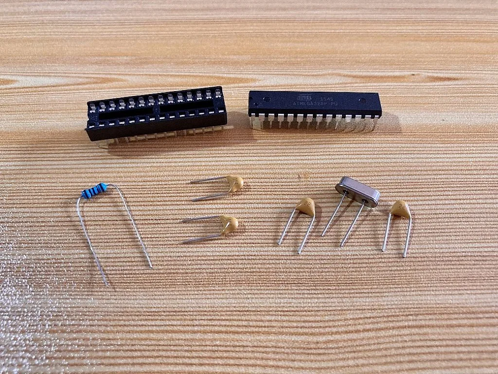
In the previous part of this project/tutorial, we have shown the components needed to build this non-contact forehead IR thermometer. In this part, we are going to discuss the hardware of this non-contact forehead IR thermometer and its operation. We will also discuss the function of the main components and how they are all connected.

The image above shows the block diagram of the non-contact forehead IR thermometer. As you can see, what makes this thermometer operate without any physical contact are the sensors. The operation of this thermometer is very simple. It simply scans the forehead temperature of someone who positions his or her forehead at the temperature sensor within 2cm to 7cm range and then displays the result on the OLED display.
When all hardware initializations are done, the first thing that the thermometer will do is to make the ultrasonic sensor measure the distance of any object within 2cm to 400cm range. If someone positions his or her forehead at the temperature sensor and the distance between the forehead and the temperature sensor measured by the ultrasonic sensor is within a 2cm to 7cm range, the microcontroller (MCU) will send a command to the temperature sensor to scan the temperature and then the MCU will turn ON the buzzers to generate short beep sounds indicating that the temperature sensor is scanning the forehead temperature. When the temperature sensor is done scanning, it sends the data to the MCU and the MCU processes the data. The MCU will turn ON the buzzers again to generate short beeping sounds indicating that the temperature scanning is done and the data has been processed. Then the MCU will display the results on the OLED display.
So basically, that is how the forehead infrared thermometer works without any physical contact. However, if the ultrasonic sensor doesn’t sense any object within the 2cm to 7cm range for about 30-40 seconds (before or after scanning temperature), the MCU will enter into low power mode to save energy, especially when it is running on battery power. In order to exit low power mode, a motion sensor is included in the thermometer. When the motion sensor senses any motion, the MCU will exit low power mode and operate again.
Now let’s try to check and briefly discuss the components used in this non-contact forehead IR thermometer.
Microcontroller (MCU)
The MCU used in this thermometer is the ATmega328P-PU (MCU used in Arduino Uno R3). It was configured as a standalone or minimal Arduino Uno. This way, we can just use the Arduino IDE and other libraries compatible with Arduino to program the MCU easily.
Temperature Sensor
For the temperature sensor, I used the MLX90614 device (GY906 module). The MLX90614 is a digital non-contact IR thermometer in a TO-39 can package containing an IR sensitive thermopile detector chip and a signal conditioning ASIC. It can measure ambient temperature from -40°C to +125°C and object temperature from -70 to +380°C, with an accuracy of 0.5°C within 0°C to +50°C range for both ambient and object temperature. The measurement resolution of MLX90614 is 0.02°C and its object emissivity is 1 by default. The emissivity can be changed by the user from 0.1 to 1.

The MLX90614 are available in 3V and 5V versions and in different package options with different Field Of View (FOV) up to 35°. The measured value of the sensor is the average temperature of all objects in its FOV. To have a more accurate reading of the forehead temperature, the distance between the sensor and the forehead should be short.
Ultrasonic Sensor
For measuring the distance between the forehead and the sensor, I selected the most commonly used ultrasonic sensor in the Arduino community, the HC-SR04 module. The detection range of the HC-SR04 module is from 2cm to 400cm or 0.0656ft to 13.1234ft. If you want to learn more about the HC-SR04 module, you can check Sergey’s tutorial here: Obstacle Avoidance Robot - Part 14 Microcontroller Basics (PIC10F200)

Motion Sensor
For detecting motion so that the MCU can exit low power mode, I used the AM312 PIR motion sensor. It has three pins, VCC, OUT, and GND. This motion sensor is very easy to use. By default or when no motion is detected, its OUT pin is just LOW. When motion is detected, the OUT pin will then output a HIGH signal.

OLED Display
The results such as the distance between the forehead and the sensor, the ambient temperature, and the body temperature are displayed on a 128 by 64 pixels OLED Display. The display size is just around 0.96 inch diagonal which is small but it is very readable thanks to the high contrast of OLED displays. It is driven by an SSD1306 OLED driver with a controller which communicates to the MCU using the I2C protocol.

Buzzers
In order to give a sound signal to the user if the thermometer is ready to be used, or scanning the temperature, or has already finished scanning the temperature, I used two 0.5 inch diameter buzzers. These buzzers operate on a 5V power supply. However, they draw around 30mA so I used 2N3904 NPN transistors to drive the buzzers.

All of the components used in the non-contact forehead infrared thermometer are powered by a 5V power supply.

Now, to see how the components are connected to the MCU, let’s check the schematic diagram above. Let’s start with the MLX90614 temperature sensor. The MLX90614 or the GY906 breakout board has 4 pins, two for its power supply (pin 1 VIN and pin 2 GND) and two for I2C communication (pin 3 SCL and pin 4 SDA). The power supply pins are connected to VCC and GND, the same power source for the MCU. The SDA and SCL pins of the MCU are on pin 27 and pin 28, respectively. So pin 3 of the GY906 board is connected to pin 28 of the MCU while pin 4 of the GY906 is connected to pin 27 of the MCU.
Next is the HC-SR04 ultrasonic sensor. The ultrasonic sensor also has 4 pins, two for its power supply (pin 1 Vcc and pin 4 Gnd) and the other two are pin 2 Trig and pin 3 Echo. The power supply pins of the ultrasonic sensor are also connected to the same power source where the MCU and the GY906 power supply pins are connected. The Trig pin of the ultrasonic sensor is connected to pin 13 of the MCU where the MCU outputs the ultrasonic sensor trigger signal while the ultrasonic sensor Echo pin is connected to pin 14 of the MCU where the MCU receives the echo signal.
The AM312 PIR motion sensor, as mentioned earlier, has three pins. VCC and GND pins for its power supply (still connected to the same power source of the other components) and OUT pin for its output. The OUT pin is connected to the external interrupt pin (INT0) of the MCU, pin 4.
The OLED display, just like the MLX90614 temperature sensor, communicates to the MCU using I2C protocol. It also has 4 pins that are similar to the pins of the GY906 board but were arranged differently. The power supply pins are switched. The GND is on pin 1 while VCC is on pin 2 (still connected to the same power source of the other components). The OLED display SDA and SCL pins are also connected to pin 27 and pin 28 of the MCU, respectively. However, there are additional 10kΩ pull-up resistors connected to the OLED display I2C pins unlike in the MLX90614 I2C pins.
The buzzers BZ1 and BZ2, driven by the 2N3904 npn transistors Q1 and Q2, are connected between VCC and the collector terminal of the transistor. Both emitter terminals of Q1 and Q2 are connected to GND. The base terminals of Q1 and Q2 are connected to pin 11 and pin 12 of the MCU, respectively, through their base series resistors R6 and R7. When the MCU outputs high signal on pin 11 and pin 12, the transistors Q1 and Q2 act as closed switches then the buzzers turn ON. If you don’t know how to use a BJT transistor as a switch, you can check this tutorial here: How to use a Bipolar Junction Transistor (BJT) as a Switch?
The red LED with its 2.2kΩ series resistor connected to pin 15 of the MCU acts as an extra indicator. This red LED turns ON during hardware initialization, during temperature scanning, and when the MCU enters and exits low power mode. The green LED with its 47kΩ series resistor is for power indication.
To monitor the activities or processes of the non-contact forehead infrared thermometer, I added some Serial.print() functions in the code. The data or messages can be sent by the MCU to a computer using a USB-to-Serial converter and we can monitor them through Arduino IDE Serial Monitor. The UART header connected to pin 2 and pin 3 of the MCU is where we can attach a USB-to-Serial converter.
Though we can just program the MCU on a breadboard, if there are changes in the program later, it’s much easier to reprogram the MCU using an ICSP header. So I added an ICSP header in the forehead infrared thermometer. Its pins are connected to pin 1 (SS), pin 17 (MOSI), pin 18 (MISO), and pin 19 (SCK) of the MCU. The other two pins are for power supply while the MCU is being programmed.
The POWER header, as shown in the schematic diagram, is where we are going to connect the main power supply for our non-contact forehead IR thermometer when it will be running in standalone mode.

This non-contact forehead IR thermometer uses two PCBs. The MCU, sensors, display, and indicators are mounted on the first PCB while the power supply is mounted on the second PCB. The block diagram above shows the components mounted on the power supply PCB. As you can see, there are two options for the power source of the thermometer, battery power or USB power. The battery power here is composed of two AAA batteries connected in series to produce 3V. The boost converter then converts the 3V output of the AAA batteries to 5V. For the USB power, you can just connect any USB power supplies to the microUSB connector port.
To select between the battery or USB power, a 3-pin header is added to the power supply board. The middle pin of the 3-pin header is connected to the POWER header. To select battery power, just short the 1st pin to the middle pin or short the 3rd pin to the middle pin to select USB power. You can check the schematic diagram of the power supply board below to see a more detailed connection of the components. Switches can be connected to J1 and J6 to disconnect the battery from the boost converter and cut off the thermometer's power, respectively.

So that’s all for the hardware part! In the next part, we are going to discuss the software of this non-contact forehead IR thermometer. We are going to show how we initialized the hardware and programmed the operation of the thermometer.

Authored By
JB Magoncia
JB is an Electronics Engineer who is interested in audio, embedded systems, and PCB design. He is one of CircuitBread Engineers. JB is also a musician who mainly plays piano/keyboard but can also play bass, guitar, and drums. He currently lives in Cagayan de Oro, Philippines.

Related Tutorials


Related EE FAQs
 work?")
How do Analog to Digital Converters (ADCs) work?

Answered by Uma Bharathi D

What is the difference between sonar and ultrasonic sensors?

Answered by Susie Maestre

What's the difference between a regular relay and a power relay?

Answered by Jayesh Upadhyay

What is a PWM signal?
Answered by Jayesh Upadhyay

How do Hall Effect sensors work?
Answered by Jayesh Upadhyay
Explore CircuitBread
- 224 Tutorials
- 9 Textbooks
- 12 Study Guides
- 31 Tools
- 102 EE FAQs
- 295 Equations Library
- 205 Reference Materials
- 91 Glossary of Terms
Friends of CircuitBread
-

Try OLC's Bill of Materials Tool
-

Free YouTube Product Training Guides
-

Free Aerodynamics Technical Articles


Get the latest tools and tutorials, fresh from the toaster.


