Obstacle Avoidance Robot - Part 14 Microcontroller Basics (PIC10F200)
Published
Note: Microchip recently made some changes and their newer IDE versions use the XC8 compiler for Assembly, whereas all sample code here is created for the MPASM compiler. However, the sample code has been ported to XC8 by user tinyelect on our Discord channel (to whom we are extremely grateful!) and the XC8 version of the code is at the bottom of this tutorial for your reference. To see the changes needed to switch from MPASM to XC8, please check out the process that he shared.
Hi there! This is the final “robot” tutorial I want to share with you. If you remember, our robot still has a “head” with the “eyes”, and this time we will give the robot some vision so it can see where it moves and can avoid obstacles.
In fact the “eyes” of the robot are an ultrasonic sensor. The most widespread one is HC-SR04 (figure 1). It is often included with Arduino sets. If you don’t have a set, you can buy it separately on Adafruit, Sparkfun, eBay or Aliexpress (the price is about $0.70-1.00 from the cheaper locations).

Let’s briefly consider the principle of operation of this sensor module. As follows from its name, it is based on ultrasonic waves. These “eyes” are in fact the ultrasonic transmitter and the ultrasonic receiver. The transmitter sends a short ultrasonic packet. If some obstacle appears in the way of the ultrasonic wave, it reflects and returns back to the sensor, where the receiver detects it. Knowing the speed of the sound in air (which is about 340 m/s), and the time between sending and receiving the packet (time of flight or ToF), you can calculate the distance to the object (d):

We have to divide the result by two as the wave has to cover the distance twice - from the transmitter to the obstacle, and from the obstacle to the receiver.
Usually the ToF is very short, so it’s more convenient to use it in us, and the distance is better to measure in cm, then we’ll have:


So to calculate the distance to the obstacle we simply need to know the ToF and divide it by 59.
To understand how it’s implemented with the module, let’s consider figure 2 which I copied from the data sheet of the HC-SR04 module.
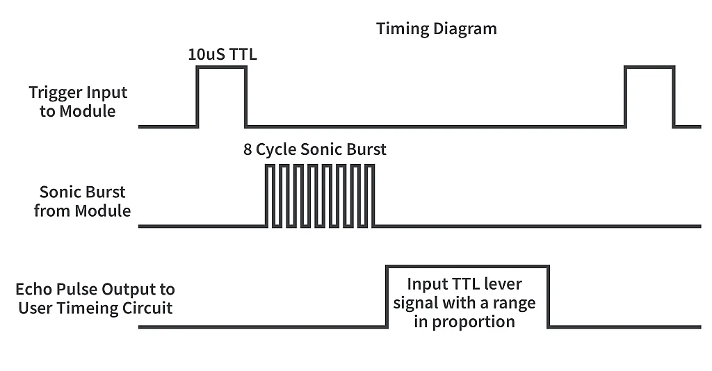
As you can see from figure 1, the module has four pins - VCC (5V), GND, Trig, and Echo.
VCC and GND are clear. The “Trig” is the trigger input of the module. You need to send the 10us pulse to this pin to start the ranging (see figure 2). After that the module will send out an 8 cycle burst of ultrasound at 40 kHz and set its Echo output as high. When the receiver detects the reflected wave, the Echo goes low. Thus the Echo pulse width represents the ToF time which we need for calculation the distance. As the module simplifies the process, the only thing we need to focus on is measuring this pulse width, and converting it into the distance.
Knowing this information, we can now formulate the task. The robot should move straight forward and measure the distance to the obstacles in front of itself. When this distance is about 4 cm, the robot should stop, move backward simultaneously with turning for about 50-70 degrees. Then it should resume moving straight forward until it detects the new obstacle.
The schematics diagram of the robot is shown in figure 3. It’s also similar to the previous two ones, but now we will use the ultrasonic sensor module.
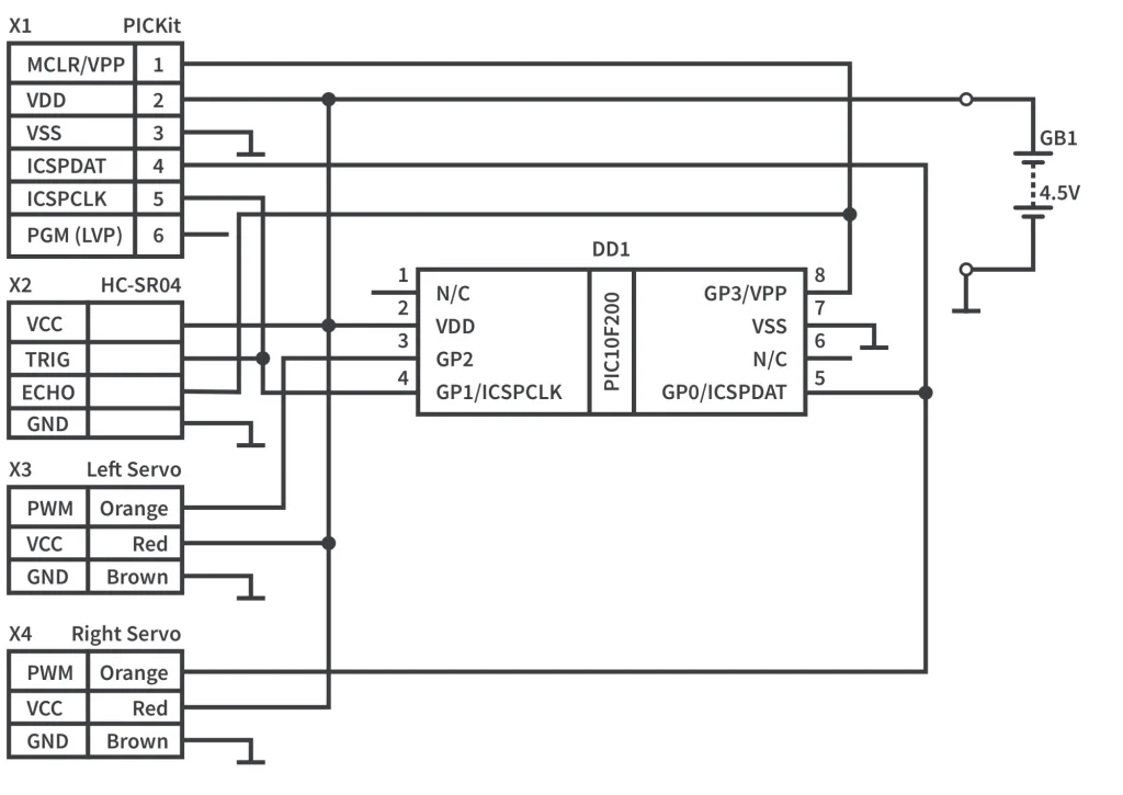
As follows from figure 3, the Trig input is connected to the GP1 pin of the microcontroller, and the Echo output is connected to the GP3 pin. There are two important notes. First, you should not change the connection because GP3 acts only as input, and thus it can be connected only to the output of the ultrasonic module. And second, you should always disconnect the Echo output during the programming to avoid breaking the module because of 12V that comes from the VPP pin of the programmer.
Luckily for us, the ultrasonic sensor does not need to be adjusted unlike the IR sensor from the previous tutorial, as it’s already factory calibrated.
The algorithm is quite clear and follows directly from the task. We should always move straight and measure the distance by means of the ultrasonic sensor. And if the distance is approximately 4 cm, we should make this back-and-turn maneuver, and then keep going moving straight and measuring the distance.
Let’s now consider the code that implements this algorithm.
#include "p10f200.inc"
	__CONFIG _WDT_OFF & _CP_OFF & _MCLRE_OFF

i   		 EQU 10   	 ;Delay register 1
j   		 EQU 11   	 ;Delay register 2
servo1   	 EQU 12   	 ;Servo1 pulse width
servo2   	 EQU 13   	 ;Servo2 pulse width
steps_back   EQU 14   	 ;Number of steps to move backward

	ORG 0x0000
INIT
	MOVLW ~((1<<T0CS)|(1<<PSA)|(1<<PS0))
	 OPTION   			 ;Enable GP2
	MOVLW ~((1 << GP0) | (1 << GP1) | (1 << GP2))
	TRIS GPIO   		 ;Set GP0, GP1, and GP2 as outputs
LOOP
    BSF GPIO, GP1   	 ;Set GP1 high
    GOTO $+1   		 ;Perform 10 us delay
    GOTO $+1   		 ;by making small 2us delays
    GOTO $+1   		 ;of each GOTO instruction
    GOTO $+1
    GOTO $+1
    BCF GPIO, GP1   	 ;Set GP1 low
    MOVLW 3   			 ;Load 3 into W: (3-1)x128us=256, 256/59=4.3cm
    BTFSS GPIO, GP3   	 ;Check until GP3 (Echo) goes high
    GOTO $-1
    CLRF TMR0   		 ;Clear Timer0
    BTFSC GPIO, GP3   	 ;Check until GP3 goes low
    GOTO $-1
    SUBWF TMR0, W   	 ;Subtract W from TMR0 to check if the
    BTFSS STATUS, C   	 ;TMR0 is bigger than 2
    GOTO MOVE_BACKWARD    ;If yes the go to the "MOVE_BACKWARD" label
MOVE_FORWARD   		 ;Move the robot forward
    MOVLW D'220'   	 ;Load the delay value for the servo 1
    MOVWF servo1
    MOVLW D'200'   	 ;Load the delay value for the servo 2
    MOVWF servo2
    CALL CONTROL_SERVO    ;Call the CONTROL_SERVO subroutine
    GOTO LOOP   		 ;and return to the main loop beginning
MOVE_BACKWARD   		 ;Move robot backward
    MOVLW 50   		 ;Load the number of steps to move backward
    MOVWF steps_back    ;And copy it into the 'steps_back' register
LOOP_BACKWARD   	;Implement the number of 'steps_back' steps
    MOVLW D'206'   	 ;Load the delay value for the servo 1
    MOVWF servo1
    MOVLW D'220'   	 ;Load the delay value for the servo 2
    MOVWF servo2
    CALL CONTROL_SERVO    ;Call the CONTROL_SERVO subroutine
    DECFSZ steps_back, F         ;Decrease the 'steps_back' and check if it's 0
    GOTO LOOP_BACKWARD    ;If not then go to the LOOP_BACKWARD label
    GOTO LOOP   		 ;Otherwise return to the main loop beginning

CONTROL_SERVO   		 ;Control the servo 1
    BSF GPIO, GP2   	 ;Set GP2 high
    MOVLW D'2'   		 ;Load 2 into the second delay register 'j'
    MOVWF j
    MOVF servo1, W   	 ;Copy the value of the servo1 into the W
    CALL DELAY   		 ;and call the delay
    BCF GPIO, GP2   	 ;Then set GP2 low
    NOP   			 ;One cycle delay before the BSF instruction
SERVO_2   				 ;Control the servo 2
    BSF GPIO, GP0   	 ;Set GP0 high
    MOVLW D'2'   		 ;Load 2 into the second delay register 'j'
    MOVWF j
    MOVF servo2, W   	 ;Copy the value of the servo2 into the W
    CALL DELAY   		 ;and call the delay
    BCF GPIO, GP0   	 ;Then set GP0 low
PAUSE   				 ;Pause between the pulses
    MOVLW D'25'   		 ;Load 25 into the second delay register 'j'
    MOVWF j
    CALL DELAY   		 ;and call the delay
	RETLW 0

DELAY   				 ;Start DELAY subroutine here
    MOVWF i   			 ;Load the W value into the 'i' register
DELAY_LOOP
    DECFSZ i, F   		 ;Decrement i and check if it is not zero
    GOTO DELAY_LOOP   	 ;If not, then go to the DELAY_LOOP label
    DECFSZ j, F   		 ;Decrement j and check if it is not zero
    GOTO DELAY_LOOP   	 ;If not, then go to the DELAY_LOOP label
    RETLW 0   			 ;Else return from the subroutine

	END
In the definition part there is a new register called ‘steps_back’ (line 8). It contains the number of steps that we will implement during the back-and-turn maneuver.
The initialization part is familiar. We will use the Timer0 again but this time not to control the servos but to measure the Echo pulse width. Also in line 14 we configure the GP0, GP1, and GP2 pins as outputs, as now GP1 will be used to trigger the ultrasonic module.
LOOP
    BSF GPIO, GP1    ;Set GP1 high
    GOTO $+1   		 ;Perform 10 us delay
    GOTO $+1   		 ;by making small 2us delays
    GOTO $+1   		 ;of each GOTO instruction
    GOTO $+1
    GOTO $+1
    BCF GPIO, GP1    ;Set GP1 low
    MOVLW 3   		 ;Load 3 into W: (3-1)x128us=256, 256/59=4.3cm
The main loop actually starts with the triggering of the ultrasonic module. First we set GP1 high (line 17). Then we have 5 identical lines GOTO $+1 (lines 18-22). As you remember each GOTO instruction takes 2 cycles, and as the frequency of the microcontroller is 1MHz, each of these lines will be implemented for 2us. The five lines give us 2x5=10us which is our target.
Actually this is a good way to implement short delays using GOTO (2us) and NOP (1us) instructions.
In line 23 we finish the Trigger pulse by setting the GP1 low.
After that we load the value 3 into the W register (line 24). This value represents the distance to the obstacle at which the back-and-turn maneuver will start. I will explain it a bit later, and now just memorize this fact.
    BTFSS GPIO, GP3   	 ;Check until GP3 (Echo) goes high
    GOTO $-1
    CLRF TMR0   		 ;Clear Timer0
    BTFSC GPIO, GP3   	 ;Check until GP3 goes low
    GOTO $-1
    SUBWF TMR0, W   	 ;Subtract W from TMR0 to check if the
    BTFSS STATUS, C   	 ;TMR0 is bigger than 2
    GOTO MOVE_BACKWARD   ;If yes the go to the "MOVE_BACKWARD" label
In line 25 we check the GP3 pin and skip the next line if it’s set. If not, line 26 is implemented and we return to line 25 again. Thus we wait until the GP3 pin goes high which means the beginning of the echo pulse. When we detect this, we clear the TMR0 register (line 27) and wait for the end of the Echo pulse (lines 28,29). The last two lines are the same as lines 25,26, we just check the opposite state of the GP3 pn.
When the Echo pulse is finished, we get the TMR0 value and subtract the value, stored in the W register from it (line 30). This value is 3, as we loaded it in line 24. Then we check the Carry/Borrow bit of the STATUS register (line 31) and if it’s set we skip line 32 and implement the “MOVE_FORWARD” part, otherwise line 32 is not skipped and we go to the “MOVE_BACKWARD” part.
Let’s now consider why we did all these things. As you remember from Tutorial 12 when we set up Timer0 we set the prescaler as 1:128, so each timer’s tick takes 128us. On the other hand as follows from the mentioned above formula d[cm] = ToF[us] / 59. This means that 1 cm corresponds to 59 us. Thus each timer tick corresponds to 128/59 = 2.1cm. So when we load 3 into the W register we expect the distance to be (3-1)x2.1 =4.2 cm.
Why 3-1, not just 3? It’s because of the implementation of the SUBWF instruction and its effect on the STATUS register. The Carry/Borrow bit of the status register is 1 when borrow did not occur, and is 0 if borrow occured. So if TMR0 > 3 then borrowing doesn’t occur, apparently. If TMR0 = 3 then 3-3 = 0, and borrow doesn’t occur again, and only if TMR ≤ 2 then borrow occurs and the C bit becomes 0. That’s why we used 3-1 in the formula.
So lines 24-32 can be translated to the normal language as “If distance to the obstacle is bigger than 4.2 cm then keep moving forward, otherwise perform a back-and-turn maneuver”.
MOVE_FORWARD   		     ;Move the robot forward
    MOVLW D'220'   	     ;Load the delay value for the servo 1
    MOVWF servo1
    MOVLW D'200'   	     ;Load the delay value for the servo 2
    MOVWF servo2
    CALL CONTROL_SERVO   ;Call the CONTROL_SERVO subroutine
    GOTO LOOP   		 ;and return to the main loop beginning
Lines 33-39 implement the part responsible for moving the robot forward. It has the same structure as in the previous tutorial. The values 220 and 200, loaded in lines 34 and 36 respectively, set the robot speed. You can select them on your own just keep in mind that the middle value is 210 (at least for me). So if you want it to move faster you can set the values of 230 and 190 for instance. In line 38 we call the ‘CONTROL_SERVO’ subroutine.
CONTROL_SERVO   		 ;Control the servo 1
    BSF GPIO, GP2   	 ;Set GP2 high
    MOVLW D'2'   		 ;Load 2 into the second delay register 'j'
    MOVWF j
    MOVF servo1, W   	 ;Copy the value of the servo1 into the W
    CALL DELAY   		 ;and call the delay
    BCF GPIO, GP2   	 ;Then set GP2 low
    NOP   			     ;One cycle delay before the BSF instruction
SERVO_2   				 ;Control the servo 2
    BSF GPIO, GP0   	 ;Set GP0 high
    MOVLW D'2'   		 ;Load 2 into the second delay register 'j'
    MOVWF j
    MOVF servo2, W   	 ;Copy the value of the servo2 into the W
    CALL DELAY   		 ;and call the delay
    BCF GPIO, GP0   	 ;Then set GP0 low
PAUSE   				 ;Pause between the pulses
    MOVLW D'25'   		 ;Load 25 into the second delay register 'j'
    MOVWF j
    CALL DELAY   		 ;and call the delay
	RETLW 0
It’s located at lines 53-72, and is absolutely the same as the ‘CONTROL_SERVO’ part of the previous tutorial, we just make it a separate subroutine because it’s more convenient for us in this program.
MOVE_BACKWARD   		  ;Move robot backward
    MOVLW 50   		      ;Load the number of steps to move backward
    MOVWF steps_back      ;And copy it into the 'steps_back' register
LOOP_BACKWARD   	      ;Implement the number of 'steps_back' steps
    MOVLW D'206'   	      ;Load the delay value for the servo 1
    MOVWF servo1
    MOVLW D'220'   	      ;Load the delay value for the servo 2
    MOVWF servo2
    CALL CONTROL_SERVO    ;Call the CONTROL_SERVO subroutine
    DECFSZ steps_back, F  ;Decrease the 'steps_back' and check if it's 0
    GOTO LOOP_BACKWARD    ;If not then go to the LOOP_BACKWARD label
    GOTO LOOP   		  ;Otherwise return to the main loop beginning
The ‘MOVE_BACKWARD’ part (lines 40-51) doesn’t have any big surprises. In lines 41-42 we load the value 50 into the ‘steps_back’ register. This is the number of steps to move backwards. You can redefine this value and see how the behavior will change.
In lines 44 and 46 we load values 206 and 220 into the ‘servo1’ and ‘servo2’, respectively. You can notice that here they are not symmetrical to the value 210. This is done to make one wheel move slower and thus perform the turning alone with the moving backwards.
In line 49 we decrement the ‘steps_back’ register and check if it’s 0. If not, we return to line 43 and move the next step backward, otherwise we return to the beginning of the main loop. Please note that during this maneuver we don’t measure the distance, and start to measure it again only after finishing the maneuver.
Actually, that’s all! It’s also quite simple. And this time you even don’t need to make the sensor adjustment which will save you a lot of time. Just be careful with the Echo output of the sensor to prevent it from breaking, and everything will be good.
The program takes just 59 words of the flash memory. We didn’t learn any new instructions again. This means that we already know more than enough to implement even complex tasks. This is a good reason to be proud of ourselves.
As homework I suggest you to change the distance threshold value, the speeds, and number of steps backward to see how these values affect the behavior of the robot.
This tutorial is the last one we planned about robots but if you have any ideas of what else you want to know how to implement, please write them in the comments, and I’ll make another tutorial if your ideas are feasible.

Get the latest tools and tutorials, fresh from the toaster.

