Practical example of Zener Diode as a Voltage Regulator
Published
TRANSCRIPT
So we have gone over Zener diodes, how they work and some of the concepts - how they're used in voltage regulation, we've gone over it conceptually, gone over it mathematically, we've gone over half wave and full wave rectifiers, and shown how those can produce a certain voltage that you want and how we can even smooth those out. But we haven't gone over and actually talked about how a Zener diode works as a voltage regulator in real life.

The first time I heard about Zener diode and the way that you can put it in reverse bias, and then it will give you exactly the voltage you want, it's like... this almost seems like magic. This is fantastic. This is awesome. But the more I learned about it, yeah, it's still awesome. But it's complicated. There are a lot of things to take into account. So right now in this very, very simple setup, we have four things that we need to worry about to make sure that this is working right. And so I'm going to go over them really quick and then we're going to mess with things and show why it's such a challenge.

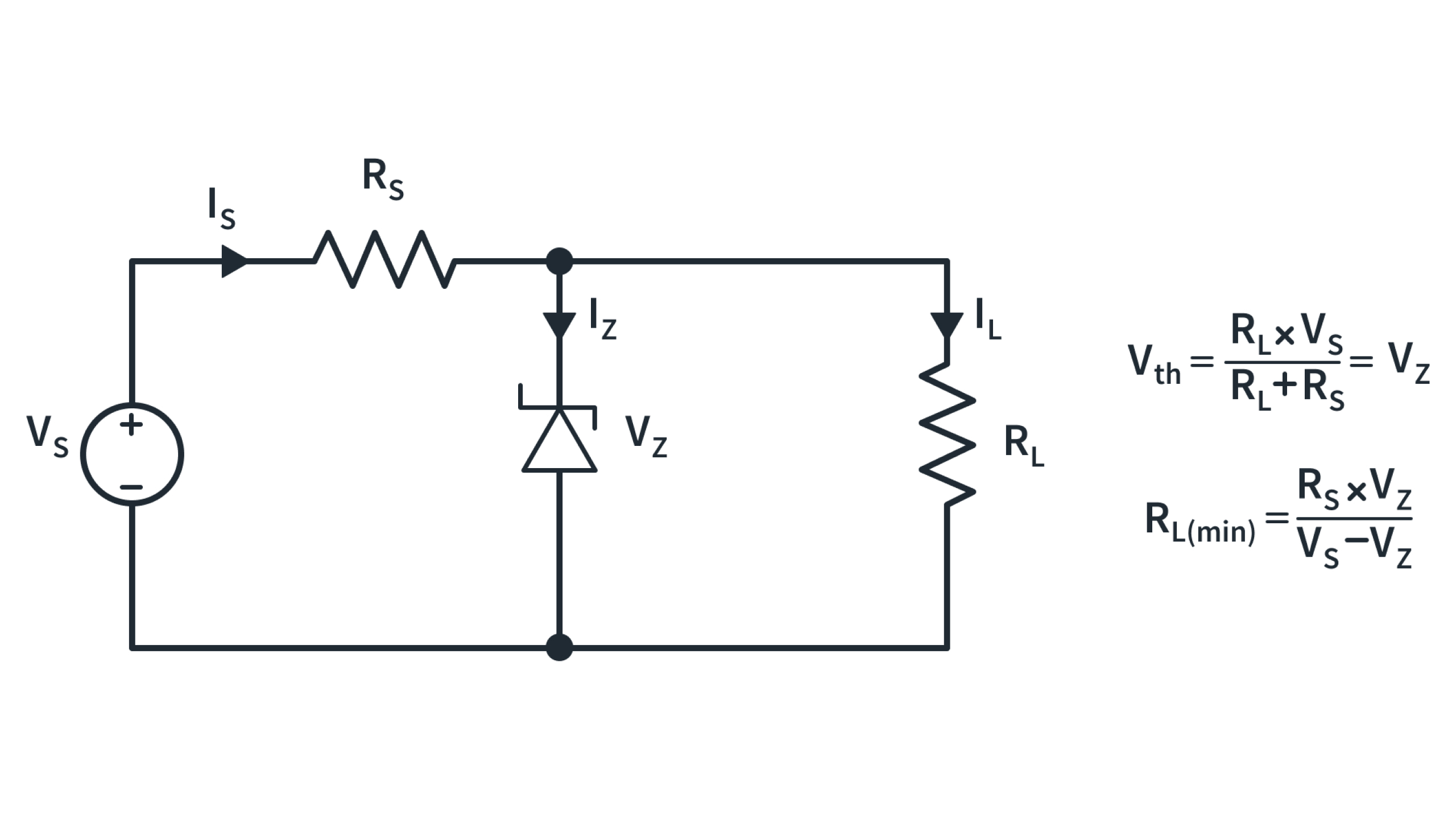
Now the first thing that we have here is actually the voltage supply. So whatever the voltage is coming in is a variable that you have to worry about. The second thing is the Zener diode itself and what it's rated for, in this case, it's rated for 5.1 volts. And then we've got our load, which is anywhere between basically a zero ohm load and a 1000 ohm load. And then we have here a resistor, that its sole purpose in life is to make it so the Zener diode doesn't blow up when there isn't any load and the voltage goes too high. And in this case, it's a 100 ohm resistor.

Now, in an ideal circumstance, this 100 ohm resistor would be pretty high-powered. It would be something along five watts or 10 watts or whatever. Unfortunately, I don't have that many resistors lying around that aren't basically quarter watt or even eighth watt. And I was looking and I couldn't find anything. So we're stuck with a quarter watt, 100 ohm resistor to act as the safety barrier there. And that's going to mean that we can't go too high with our incoming voltage as we're testing it. But that's the thing. That's the thing. That is one of the challenges of doing all of this as you have those four variables and as one of them changes everything else has to move. You're going to lose efficiency, or you're going to have other problems. So let's get into that. And let's see if I can be coherent when I am going through the different challenges here.

So the main goal of all of this is you want your voltage across the Zener diode to be 5.1 volts. That is the main goal of everything. Now it needs to be 5.1 volts in every circumstance. Now, that's never going to happen. If your input is below a certain threshold. If your input is five volts, you're not going to magically get 5.1 volts across the Zener diode. And actually, as you measure it, let's get this going. So right now, if I go below about 5.7 volts, you can see that my voltage across the Zener diode drops. So not only do you need to have 5.1 volts, you have to have a little bit over 5.1 volts for it to stay where it's supposed to and that's flashing all over the place because I'm not holding this properly. But then once you get up above that 5.7 volts, you can see it stabilized and anything over that and I still get that 5.1 volts. So that is the first thing that we need to worry about.

The second thing that you need to worry about is this resistor right here (Zener diode series resistor). This resistor, as I said, is basically so that you're not losing everything right here (the Zener diode). So just imagine that we have the load at a no load, so infinite resistance on the load, and then I have eight volts across there (from the power supply), and this is going to be 5.1 volts. If I didn't have this resistor, it would be eight volts across this (the Zener diode), this is just basically going to be conducting, in an ideal world, an infinite amount of current and that is not an ideal thing. So we put this resistor just like you do with an LED to make it so that you don't have some crazy current flowing through this when there is a higher voltage across the diode than you want.
So, that's great, but at the same time, all of the current that is flowing through this gets turned into waste heat. It's just completely wasted dissipated power and that's not ideal. So you want this to be as low as possible. But then if you're going to have 15 volts coming in, and you have a one ohm resistor there, that's not going to be enough to protect the diode. And if you have a humongous resistor in there, then it's going to make it so if you have a very large load, any current that wants to go through your load has to go through this and it's going to be burning power as it drops through that high resistance resistor right here as well.
So that's an interesting challenge that you need to figure out exactly what your expected load is going to be here to make it so that this can handle both having no load or basically a huge load. So anywhere from, I don't know, one microamp up to an amp or something like that. That's really where you have to do those calculations to figure it out. And again, we're not going over the math here. We have another video in that and that one we go over the math and talk about it and also probably really recommend you go to Zener Diode as Voltage Regulator - Conceptual Overview to see that math worked out to me make it easier for you.

But moving on, we have this right now I have it set up so it is a 1000 ohm load and I'm doing that because as I'm sitting here, I'm worried about burning out this 100 ohm resistor. So right now it is 0.6 volts across a 100 ohms, that comes out to about six milliamps and if I can't do that easy math in my head, this is why I don't like to do math in front of the camera unless it's completely scripted, because I'm just going to embarrass myself. But that's with this load being 1000 ohms.
So let's drop the resistance here. So we are basically increasing our load. And you can see that as we go. And we're basically having more of a draw through the load itself versus just through the diode that there is a bigger and bigger voltage drop across this resistor. And not only does that mean that we're wasting more power in this resistor, it means that we are not going to have as much of a voltage drop across here.

So now this isn't going to be 5.1 anymore because our input voltage isn't high enough. So now we're only at 4.6 volts, because this is trying to draw so much current that it has to go through here. And that's dropping too much voltage across that resistor that you're now not getting enough voltage for the Zener diode to be able to work in its capacity. And so now you need to turn up the voltage a little bit to be able to still maintain that correct load on the... whatever the load is.
So I hope that just gives you a rough idea of the complications, and really the trade offs that you have here. I think this is a perfect microcosm of what engineering is all about. Because you can't just say, Oh, well, let's just do as much as we want as big as we want and everything because if you make things as big as you want, then it's going to be incredibly inefficient. But if you make things too small, and you're going to completely for efficiency, then it's not going to be able to handle a wide range of loads. And you're going to be Oh, now that I switched the load, I have to change all these things. And that's not ideal either.
So as much as this drives me crazy, because it's kind of like this weird juggling act. It really is a perfect example of what it's like to be an engineer and to try and look at what your requirements are. And look at how am I going to make this in a way that fulfills all those requirements and is inexpensive and robust and does everything that it needs to do?
So that's it. So voltage regulation with a Zener diode, I guess the summary is it's a challenge, but it's worth it because this is the basis of all modern power supply things. This, in a full-wave rectifier, switching-mode power supplies, you have a lot of different ways of approaching it. But this is one of the key ways that most things have their voltage regulated right now and it is interesting. So I hope that was helpful. Hopefully, I didn't scare you. Hopefully that was more of a, “hey that’s a challenge, I'm going to go go and approach that and see what I can do about it”. And if you like that, you found it interesting, please leave us a like, subscribe to our channel, leave any comments or questions in the comments below and we'll catch you on the next one.

Get the latest tools and tutorials, fresh from the toaster.


