Renesas RA - 10. Introduction to MCUBoot using the Renesas RA Family Part 1
Published
Using MCUboot in Overwrite Mode
Hello again! I was asked to write this tutorial prior to the other ones as this topic is quite popular according to how many questions are related to this topic on the Renesas Engineering Community forum. MCUboot is a bootloader provided and supported by the Linaro company. It is portable to several MCU platforms, including RA. Using this bootloader is quite easy, you don't even need to write a single line of a code! Yet it’s quite powerful, and handles the firmware integrity and authenticity check after start-up and the firmware switch part of the firmware update process.
In this tutorial I will mainly rely on the R11AN0516 application note “Secure Bootloader for RA2 MCU Series.” Actually, this application note is quite good and explains a lot about using MCUboot but some things remained beyond its consideration, so let’s go through all the steps from setting up the environment and creation of the bootloader application to downloading the target application using the built-in bootloader.
Even though we will not write a lot of code in this tutorial, it still will be quite long because of the large number of figures. So I will split it into several parts. In this part, we will go through all of the steps from scratch. In the next part, we will consider different modes of operation of the MCUboot. In the final part, we will write a custom application to download the code into the MCU (as MCUboot doesn’t provide any means for this).
The task for this tutorial is to create the bootloader application and the customer’s application and run the last one using the first one. Then modify the customer’s application in different ways and check how the bootloader will manage this.
Requirement Hardware and Software
As for the hardware, we need any Renesas development board with the RA2 MCU. I will use my EK-RA2A1 board as, so far, it is the only one I have, but you can use whichever you have, the steps will be the same.
As for the firmware, I will use the following:
- e2 studio v.22.4.0.
- FSP v.3.7.0. By the moment of writing this tutorial Renesas has released the FSP v. 3.8.0 but for some reason when I tried to create the bootloader project with it, it gave an error. Maybe after some time this issue will be fixed but for now let’s use the FSP v.3.7.0. The latest releases of e2 studio and the FSP can be downloaded in this page: https://github.com/renesas/fsp/releases.
- Python 3. Yeah, surprisingly, we need Python this time as it will be used to sign the application image when used with MCUboot. Now the latest version is 3.10.5 which can be downloaded here: https://www.python.org/downloads/.
As you see, the list is quite impressive for such a “simple” application but what can you do? The simplicity of the configuration is compensated by the number of steps to perform.
Introduction to MCUboot
As I mentioned before, MCUboot is the multiplatform code that checks the integrity and the authenticity of the code, and copies and runs it if everything is good. As I also wrote above, MCUboot doesn’t provide the means to download the firmware file into the flash memory of the MCU, this task lays upon the user’s application. For testing purposes we will download this file by means of the JLink debugger and e2 studio, but in real conditions such an approach is not applicable.
To better understand how MCUboot works, let’s consider the memory flash map (which I’ve taken from this application note), Fig. 1

I wrote “single image” in the Fig. 1 title, as it can be two images: for trusted and non-trusted zones. But as they exist only in Cortex-M33 core, the “two images” approach can only be applicable for RA6 and some RA4 MCUs.
So, as you can see in Fig. 1, in the beginning of the flash memory there is the MCUboot application. It should be as short as possible to save the memory for the user’s applications. We will see which steps are recommended by Renesas to compress it.
Above it there are two memory slots for the primary and the secondary applications. In all operation modes of the MCUboot (which we will consider very soon) these two slots are always used. So the real code size of the user’s application when using the MCUboot should be smaller than half of the flash memory of the MCU. This is another price to pay when using this bootloader.
The scratch area is used only in swap mode as an interim buffer to swap the primary and secondary application areas.
Let’s now consider the operation modes of the MCUboot. There are three of them that are currently available in the RA port:
- Overwrite mode;
- Swap mode;
- Direct XIP (eXecute In Place) mode.
To better illustrate the difference between them let’s see Table 1.
Table 1 - MCUboot Operation Modes
Mode | Memory area | Initial state | Downloading new FW | Booting | Running new FW |
Overwrite | Secondary app | Blank | App v.2 (is being downloaded) | App v.2 (has been downloaded) | Blank |
Primary app | App v.1 (is running) | App v.1 (is downloading app v.2) | App v.2 / App v.1 (copying in progress) | App v.2 (is running) | |
Bootloader | Idle | Idle | Is copying App v.2 to the primary slot | Idle | |
Swap | Scratch area | Blank | Blank | Is used as an interim buffer to copy apps | Blank |
Secondary app | Blank or any | App v.2 (is being downloaded) | App v.1 / App v.2 (copying in progress) | App v.1 (is idle) | |
Primary app | App v.1 (is running) | App v.1 (is downloading app v.2) | App v.2 / App v.1 (copying in progress) | App v.2 (is running) | |
Bootloader | Idle | Idle | Is swapping primary and secondary app areas | Idle | |
Direct XIP | Secondary app | Blank or any | App v.2 (is being downloaded) | App v.2 (has been downloaded, is idle) | App v.2 (is running) |
Primary app | App v.1 (is running) | App v.1 (is downloading app v.2) | App v.1 (is idle) | App v.1 (is idle) | |
Bootloader | Idle | Idle | Swapping the context to run secondary app | Idle | |
Secondary app | App v.1 (is running) | App v.1 (is downloading app v.2) | App v.1 (is idle) | App v.1 (is idle) | |
Primary app | Blank or any | App v.2 (is being downloaded) | App v.2 (has been downloaded, is idle) | App v.2 (is running) | |
Bootloader | Idle | Idle | Swapping the context to run primary app | Idle |
So in the overwrite mode the application is always executed from the primary slot and the new application is always written to the secondary slot. After the startup bootloader checks if there is valid firmware (FW) in the second slot, and if it is present there, copies it to the primary slot, overwriting the existing FW. After that bootloader erases the secondary slot and starts the execution of the new FW. Such an approach is quite simple and straightforward. It spends less memory than the swap mode because the scratchpad area is not needed. Also it is fail-safe and resistant to power loss, as if something happens during the loading of the new FW, it will not pass the validation after reset, and the old FW will remain working. As a drawback of this mode, one can name the absence of the pretesting of the new image before overwriting. So if something goes wrong from the logic perspective in the new FW, it will still overwrite the old code, and thus may make the device non-functional.
In the swap mode, the application is also always executed from the primary slot. The new FW is downloaded in the secondary slot. After validation of the new FW, bootloader swaps the slots content using the scratchpad area as an interim buffer, and then runs the new application from the primary slot. Using the scratchpad causes two main drawbacks in this mode:
- swap mode requires more flash memory than others due to necessity of having the scratchpad area;
- faster wearing of the flash memory in the scratchpad area because of many write operations during the swapping process.
However, this mode has more advantages than the previous one. It also supports a fail-safe and is resistant to power loss while the FW is downloading. It allows testing the new FW, and if it doesn’t work properly, it can swap the slots again and thus rollback to the previous working version.
The direct XIP mode is different from the previous two. Unlike others, it allows the MCU to execute the code from both slots. And the new FW can also be downloaded in different slots: if the current application runs from the primary slot, the new FW is downloaded to the secondary slot, and vice versa. In this mode two FW images should always be present in both slots. The same as other modes, this one is fail-safe and resistant to power loss. Also it is the fastest because it doesn’t need to copy the code from one flash memory area to another. Though in this mode you need to add some specific code to your applications which will select the slot from which to execute.
Now that we’ve reviewed the separate operating options in depth, I recommend going back up and reviewing the table again to get a better high-level understanding of the differences.
MCUboot itself also supports the RAM loading FW update which is similar to the direct XIP mode but it copies the active image to RAM to speed up the code execution. This mode is not currently supported by the RA FSP.
As I mentioned before, today we will consider how to create and configure the MCUboot application in the overwrite mode. So, let’s start.
Bootloader Application Creation and Configuration
Let’s create a new RA project. In this step there are no any tricks and differences, just the project based on C language and “Bare Metal - Minimal” template. Don’t forget to set the FSP version as 3.7.0 because the latest (3.8.0) gives the error, as I said before. Let’s give this project a specific name - “mcuboot_overwrite_with_signature”, as I will refer to it several times, so you won’t wonder what that text means. The last part of the project name means that we will sign the FW file with the secured keys to provide authenticity checking.
Now let’s do the first step in the project size optimization and open the “Pins” tab in the FSP configurator. Here in the drop-down list “Manage configurations…” we need to select “R7FA2A1AB3CFM.pincfg” (Fig. 2) and deselect the checkbox “Generate data”.
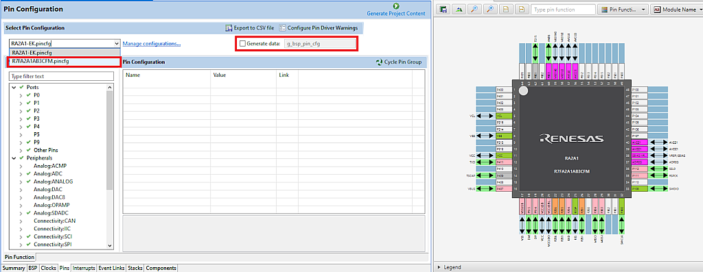
The first option “RA2A1-EK.pincfg” configures the pins according to their functions in the EK-RA21 board, including ADC, communication interfaces, touch sensor etc. While the second option is the configuration of the clean MCU with the minimum required pins.
Then you need to set the checkbox “Generate data” and type the same text as it was initially “g_bsp_pin_cfg” (Fig. 3).

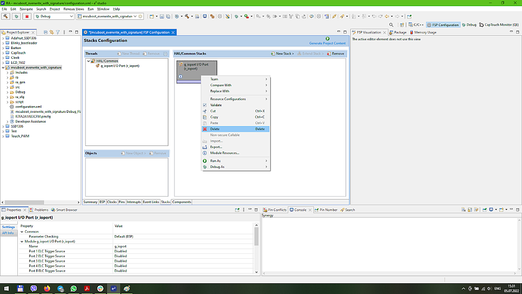
If you compare the right parts of Fig. 2 and Fig. 3, you may notice that in the second case all the pins except for the power ones are unconfigured. Moreover, as the MCUboot doesn’t use any pins, we can switch to the “Stacks” tab and delete the block “g_ioport I/O Port”.
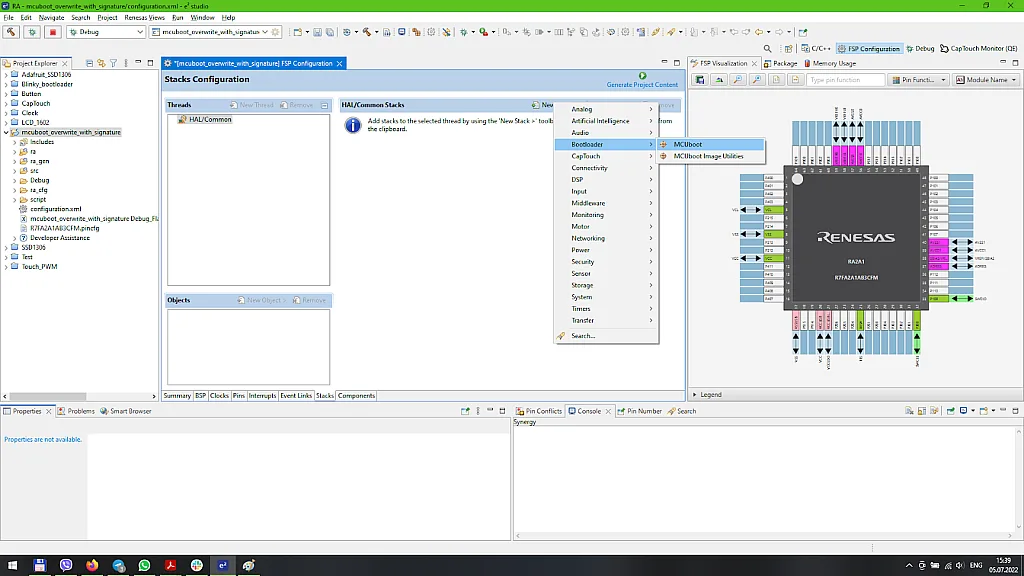
Now let’s add a new stack called “MCUboot” from the “Bootloader” list (Fig. 5).
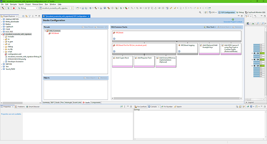
As you can see (Fig. 6), the stack is really large and has a lot of blocks but we will configure just a few of them, the rest have the configuration by default and either don’t have any properties to change or the properties are locked.
Let’s configure the biggest upper block “MCUboot” in the “Properties” window (Fig. 7).

As you can see, there are not very many options to change. Let’s consider them in more detail. For more information you always can click the
symbol. But in this current case you need to click this symbol in the “MCUboot port for RA (rm_mcuboot_port)” block because in the “MCUboot” block this symbol leads to the Linaro MCUboot Github page.
- “Custom mcuboot_config.h” field allows writing the path to the custom mcuboot_config.h file. By default this file is created by the FSP configurator based on the options set in Fig. 7. But you can create your own file if needed. By default it’s located in the “<project name>\ra_cfg\mcu-tools\include\mcuboot_config\” folder.
- “Upgrade mode” sets one of the modes that I described in the previous section. The options are “Overwrite Only”, “Overwrite only Fast”, “Swap” and “Direct XIP”. The difference between the two first options is that in the Fast mode not the whole secondary slot is copied into the primary slot, but only the part occupied with the FW image. We will select the “Overwrite Only” option to prevent any unexpected behavior. I didn’t find any information but I suspect that if the new FW is shorter than the old one, the unerased parts of the primary slot will remain there and can potentially cause some problems if you don’t take care of them.
- “Validate Primary Image” makes the bootloader check the signature of the FW in the primary slot every time before booting. This makes the start time longer but improves security. We will enable this option.
- “Downgrade Prevention (Overwrite Only)” allows the bootloader to check the FW versions (we will consider later how to set it), and if the new FW has a smaller version number than the current one, it will not be updated. This option (as follows from its title) is only applicable in the Overwrite Only mode. Let’s enable this option and check later how it works.
- “Number of Images Per Application” sets the number of FW files to be updated. This number can be 2 if we use the Trust Zone application (which is available only in Cortex-M33 core), or 1 in all other cases. So we leave this value as 1.
- “Watchdog Feed” permits us to specify the function name which will be implemented during the FW update process if the watchdog timer is enabled. The updating process can take a long time especially in Swap mode, so the WDT can reset the MCU which we need to prevent.
- The next two fields “Measured Boot” and “Data Sharing” allow sharing the boot information and some specific information between the bootloader and the user’s application. If you enable them you need to define the address of the shared memory in the RAM. For now we don’t need this functionality, so let’s leave these fields disabled. (For some reason I didn’t find any information about these options in the Renesas documentation, and the only clue about using them was found at the Nordic site).
- “Signature type” sets the type of the signature in case of enabling the “Validate Primary Image” option. The next options are enabled: “None”, “ECDSA P-256”, “RSA 2048”, and “RSA 3072”. Please note that the RSA types are only available when you select the MbedTLS Crypto stack. I will talk about this later when we get to this point. For now let’s leave the default value “ECDSA P-256”.
- “Boot record” according to the official information, says that it “Creates CBOR encoded boot record TLV”. This field is not very much clear, but as I understand, it should be enabled when the “Measured Boot” field is enabled. So let’s leave it blank.
- “Custom” allows adding a custom argument to the “imgtool.py” script. This script is used to sign the user’s application, we will consider it later. This field can have two values: “--confirm” and “--pad”. The behavior of the bootloader with the “--confirm” argument is the following:
- In Overwrite Only mode, the new image will always overwrite the old application in case of the successful verification.
- In the Swap mode after the first update, the primary slot will be marked as Confirmed, and at the next resets no swap will happen.
- In the Direct XIP mode there is no swapping of the images, so the argument type doesn’t matter.
The behavior with the “--pad” argument is the following:
- In Overwrite Only mode, the behavior is the same as with the “--confirm” argument.
- In Swap mode, it’s left to the application to mark the image as Confirmed. We will consider how to do this in the next part.
- “Python” sets the name of the Python command. If it was added to the PATH system variable upon installation, just “python” is enough. If you have several versions of the Python on your PC, you might need to change it to “python3” or write the full path to it.
- “Bootloader Flash Area Size (Bytes)” sets the flash size reserved for the bootloader. Its value should be a multiple of 0x800 as it’s the minimum flash block size to erase. We set the value 0x3800, and I’ll show later how to calculate it.
- “Image 1 Header Size (Bytes)” is the flash size reserved for the image header. This value is core specific: for Cortex-M23 it should be 0x100, and for Cortex-M4 and Cortex-M33 it should be 0x80.
- “Image 1 Flash Area Size (Bytes)” sets the flash size reserved for the user’s application. This value also should be multiples of 0x800. Please note that this value should be always less than the max size of the flash memory minus size of the bootloader area.
- “Scratch Flash Area Size (Bytes)” sets the flash size reserved for the scratchpad area. It should be set only in the Swap mode, and its minimum value is 0x800. Here we leave it as 0, as we use the Overwrite mode.
- “Data sharing” list is used only if we enabled data sharing above. So we will not consider it here in detail.
That’s all we need to know about the MCUboot block configuration. Let’s now add the missing blocks to get rid of the error (as you can see in Fig. 6, the MCUboot block is red).
Let’s click on the “Add Crypto Stack” block, and in the “New” list select “TinyCrypt (S/W only)” (Fig. 8).
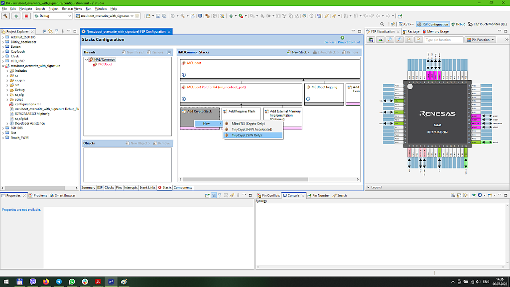
TinyCrypt is a small cryptography library. It’s also a multiplatform library which is currently supported by Intel corporation: https://github.com/intel/tinycrypt/. In MCUboot it’s used for checking the application image integrity and authenticity. As the MCUboot library doesn’t support the hardware modules provided by the RA MCU, we select the “S/W only” option. As I mentioned before, TinyCrypt doesn’t support the RSA, that’s why we selected ECDSA P-256 in the MCUboot properties.
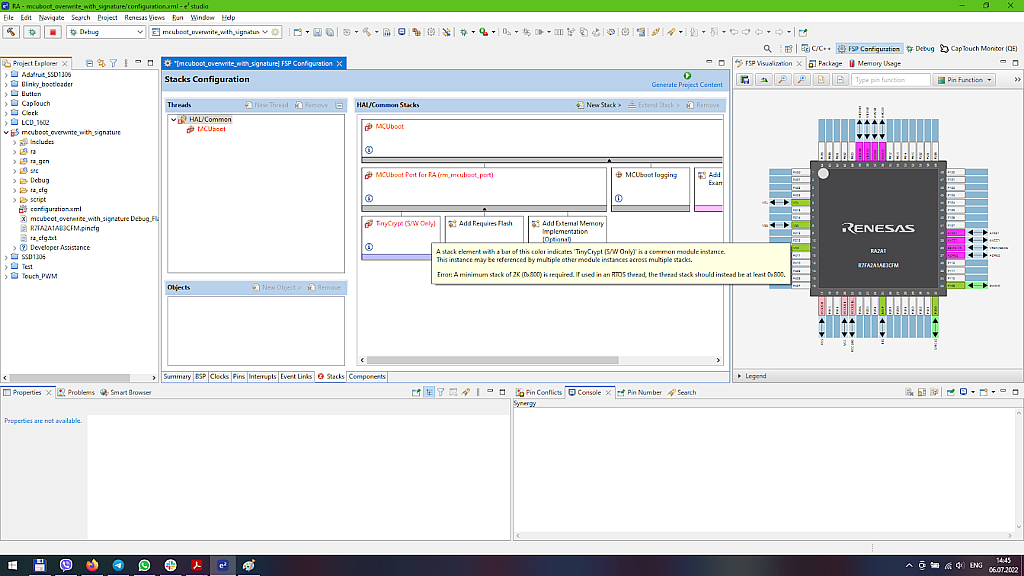
When you have added this stack, you may notice that it also is red which means that something is wrong. If you move the mouse above this block, you can read that it requires a bigger stack size (Fig. 9).
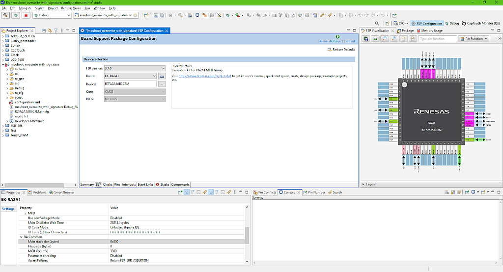
So let’s switch to the “BSP” tab and increase the stack size in the “Properties” window (Fig. 10).
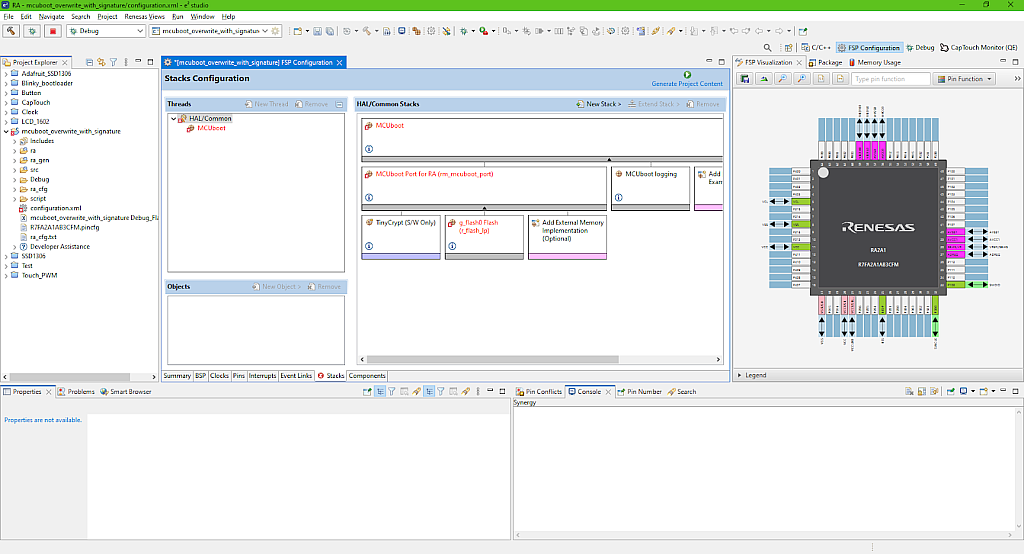
Then, when we return to the “Stacks” tab, we can see that the TinyCrypt error has gone. Then we need to click on the “Add Required Flash” block, and in the “New” list select the only option “Flash (r_flash_lp)”. You can see that it also appears with an error (Fig. 11).
Let’s configure this stack in the “Properties” window (Fig. 12).

- “Code Flash Programming” enables or disables writing to the code flash area. As the bootloader is intended to do exactly this, we must enable this option.
- “Data Flash Programming” enables or disables writing to the data flash area. Data flash is used to store some user data, like arrays, settings etc. We will not use this area, so we can freely disable this option.
- “Name” is the name of the Flash stack, it can be anything. Let’s leave it unchanged.
- “Data Flash Background Operation” enables operation with the data flash in the background without pausing the program execution. We also don’t need this option, so we disable it.
- “Callback” is the user callback function called when the data flash background operation is completed.
- “Flash Ready Interrupt Priority” sets the interrupt priority level.
As we don’t have external flash connected, we leave the block “Add External Memory Implementation (Optional)” unused. By the way, even if you try to add it, you will see that it’s unsupported in this MCU.
The next block “MCUboot logging” allows sending the logging information via Segger RTT but we will not do this in the current tutorial.
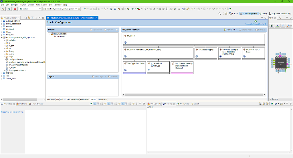
As we are going to perform image validation, we need to add the encryption keys. So click on the block “Add [Optional] Add Example Keys” and select the only option “MCUboot Example Keys (NOT FOR PRODUCTION)”. This block provides the example security keys which can be used for testing but not for production as they are publically available to everyone and don’t actually have any security.
And finally let’s click on the last block “Add ANS.1 parser if using TinyCrypt or Custom Crypto (Protected Mode)”, and select the option “MCUboot ANS.1 parser” in the “New” list. This parser is needed when using the ECDSA P-256 encryption type, as the ECDSA P-256 key is stored in the ANS.1 format.
The whole MCUboot stack should now look like this (Fig. 13).
Now we can click on the “Generate Project Content” button to generate the project code. Then open the “hal_entry.c” file. We will make some changes in it.
First we need to remove the unnecessary lines. They are all located in the R_BSP_WarmStart function. There we need to remove lines 31-38 which are about reading the data flash, and lines 43-46 as we don’t use the GPIO module in the current project (Fig. 14).

Now I will show you how to do a trick which I myself have learned just recently. We need to add the MCUboot code to our application but there is a way to do this without writing it manually. So we need to expand the “Developer Assistant” in the “Project Explorer” window, then consequently expand the lists “HAL/Common”, “MCUboot”, “Quick Setup”, and select the “Call Quick Setup” (Fig. 15).

Once you have selected it, drag and drop it to line 6 of the “hal_entry.c” file. You will see that the new code has appeared there (Fig. 16).

Convenient, isn’t it? Now we need to invoke this function inside the hal_entry function right after the /* TODO: add your own code here */ reminder (Fig. 16). Don’t forget to do this! I spent about an hour trying to figure out why the bootloader didn’t work, and it turned out that I just forgot to call it from the hal_entry function.
The next steps will all be devoted to reducing the bootloader application size. Disclaimer! These all steps are taken from the R11AN0516 application note “Secure Bootloader for RA2 MCU Series” and are not made up by me. You can skip them if you don’t care too much about the bootloader application size but it’s recommended to implement them.
The first thing we will do is to update the linker script to put our code into the unused memory space between the vector table and the ROM registers. Sounds scary, right? Let’s figure out what I mean. As an illustration to my words I will take Fig. 22 from page 17 of the above mentioned application note and present it here (Fig. 17).

The blue regions are in use by default. At addresses 0x00 - 0x40 there is the interrupt vector table, at addresses 0x400-0x500 initially there are the ROM registers which are all the registers used to configure the MCU. And only from address 0x500 the user application starts. In our case it’s the bootloader application.
What we will do is to change the linker file which is used to define the memory sections, so we can put some code in the gap at addresses 0x40 - 0x400. And also we will reduce the area of the ROM registers because in fact they occupy the addresses from 0x400 to 0x43C. In this way we can save (0x400 - 0x040) + (0x500 - 0x43C) = 0x484, or 1156 bytes. Actually you can use this approach in other applications if there is a lack of flash memory.
So, let’s now open the mentioned above linker script file which is called “fsp.ld” and is located in the project folder “scripts” (Fig. 18).
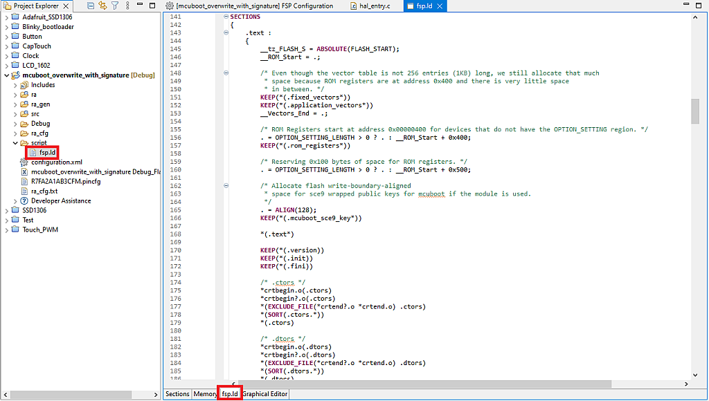
When you open this file you will see some tables by default. Please don’t edit them. I don’t know why but for some reason if you do this, the script file breaks, and you never can build the project again. So we will skip all these visual configurators and open the tab “fsp.ld” (I marked it with the red box in Fig. 18). Here you can configure it manually.
Scroll down the file to the part SECTIONS (line 141 in my case, see Fig. 18). Here we need to make some changes. First, we need to define the new section .code_in_gap* between the .application_vectors* and .rom_registers* sections. Second, we need to reduce the size of the .rom_registers* section from 0x500 to 0x43C. And finally, comment out the section .mcuboot_sce9_key* as it’s not used in the current application. All the mentioned changes are marked in Fig. 19 with the red frames.
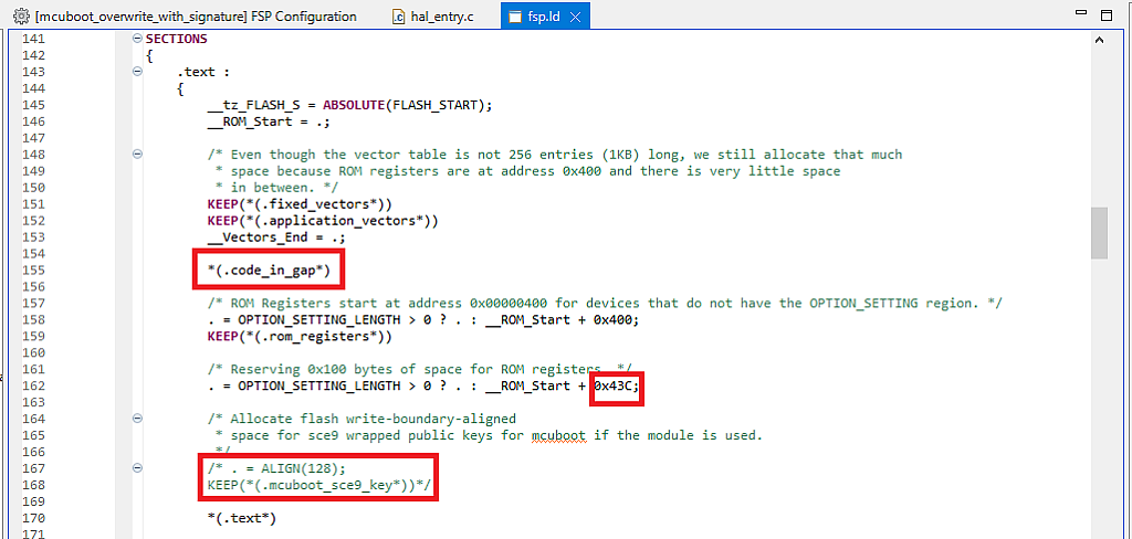
OK, we have defined the new memory section, and now we need to put some code into it, as by default the application will start from the 0x43C address. To do this, there is the special macro definition BSP_PLACE_IN_SECTION which should be placed after the function declaration. In the application note there are recommendation of what functions to put into the .code_in_gap* sections. I don’t know why exactly these functions have been selected, but I just followed the instructions. If you are curious enough, you can try to put some other functions there and see what will happen.
In the file “hal_entry.c” we put the functions R_BSP_WarmStart and mcuboot_quick_setup to the .code_in_gap* section. To do this, we need first to create the declaration of the function mcuboot_quick_setup, which, as you remember, we dragged and dropped from the Developer Assistant, and then write the text BSP_PLACE_IN_SECTION(".code_in_gap*") after both functions’ declarations (Fig. 20).

The last three functions are located in file “\ra\mcu-tools\MCUboot\boot\bootutil\include\bootutil\image.h” and are called bootutil_img_validate, bootutil_tlv_iter_begin, and bootutil_tlv_iter_next (Fig. 21).

If you now try to build the project, you will see the error that the code doesn’t fit into the flash memory. To prevent this error we need to perform the next size reducing step - code optimization. By default the optimization is set at the middle level, and we can enable it by default. To do this, right click on the project name, and in the drop-down menu select the last line “Properties”. Then in the opened window expand the list “C/C++ Build” in the left part, and select the line “Settings”. Then in the central part of the window select the line “Optimization”. In the right part select “Optimize Size (-Os)” at the “Optimization Level” drop down list (Fig. 22).

This optimization level tells the compiler and linker to optimize the code to reduce the generated FW file size as much as possible, which we need.
Let’s also change one more setting while the “Properties” window is opened. We need to switch to the “Build Steps” tab and in the “Pre-build Steps” - “Command(s)” field add the command del ${ProjName}.elf (Fig. 23).

This command will delete the “elf” file which is the executable downloaded to the MCU every time before building the project. This option may be useful, because if you change some project settings settings or linker script, but not the code itself, the “elf” file will not be rebuilt. So you may think that you have applied the changes but in fact you have not, and then spend some time trying to figure out what is wrong until you notice that the “elf” file was not updated for a long time. Very frustrating situation, I’ve been there… So add this option, it can really save you a lot of time and nerves.
Now we can click the “Apply and Close” button and build the project. This time there will be no errors. After building you can see the code size statistics in the “Console” window (Fig. 24).

The “text” column is the code flash size, the “data” column is the data flash size, the “bss” column is the used RAM size, the “dec” and “hex” columns are the total used memory sizes in decimal and hexadecimal format, respectively.
We are now interested in the code flash size which according to Fig. 24 is 13112 bytes. In hexadecimal format this value is 0x3338. The nearest bigger number that is multiples of 0x800 is 0x3800, and this is the value that we have put in the “Bootloader Flash Area Size (Bytes)” in the MCUboot stack option (Fig. 7). So one less riddle in this project.
The next paragraph is just out of curiosity, so you can skip the part till the end of the chapter if you are not very curious.
Let’s open the “Memory Usage” window to see how the functions, that we put into the .code_in_gap* section, are allocated. This window can be found at the main menu “Renesas Views” - “C/C++” - “Memory Usage” (Fig. 25).

In the opened window switch to the “Symbol” tab and notice the five functions from R_BSP_Warm_Start to bootutil_tlv_iter_next (Fig. 26).

As you remember the .code_in_gap* section starts at address 0x40 where the R_BSP_Warm_Start is located, and ends at the 0x400 address. The bootutil_tlv_iter_next function ends at the address 0x36B, so we have filled almost the whole section. We can calculate the total size of all five functions there using the Size (bytes) column: 2 + 46 + 468 + 150 + 146 = 812 bytes, and the .code_in_gap* section size is 0x400 - 0x40 = 0x3C0, or 960 bytes. As you can see, there are still almost 150 free bytes which can be filled with something.
Python Signing Environment Configuration
And here we get to use Python. Well, actually not exactly “we”, it will be used automatically by the IDE, we just need to set it up. Please note that the steps described in this chapter need to be implemented just once, I mean once total, not once for every project. So if you already have configured the signing tool, you can skip this chapter.
First thing we need to do is to download Python 3 from this page https://www.python.org/downloads/ and install it if you still don’t have it in your system. The installation process is quite simple, you just should not forget to set the checkbox “Add Python 3.10 to PATH” at the first installation screen (Fig. 27).

For simplicity you can click “Install now” and get all required things installed automatically.
Now a brief explanation of what we do and what will happen next. So the bootloader application needs to sign the user’s application to validate it later at the booting step. The signing is implemented by the “imgtool.py” script which is located in the “ra\mcu-tools\MCUboot\scripts\imgtool” folder. This script is implemented as the post-build step during the application image build (I will tell about this in more detail in the next chapter). To configure this signing script we need to right click on the folder “ra\mcu-tools\MCUboot” and select the line “Command Prompt” (Fig. 28).

The command window will be opened with the path set to the “ra\mcu-tools\MCUboot” folder.
First, it’s recommended to update the pip (whatever it would be) by writing the following command:
python -m pip install --upgrade pip
After its implementation you will see the response presented in Fig. 29 if it’s the first time you use this command or just the first line otherwise.

Next we need to write the following command to install and verify all MCUboot dependencies:
pip3 install --user -r scripts/requirements.txt
The result of implementation of this command if you called it the first time is presented in Fig. 30, and all other times you will see the response presented in Fig. 31.


Now, every time when you build any bootloader application the signing command will be automatically added to the “.bld” file. Let’s click on the build button, then find the “mcuboot_overwrite_with_signature.bld” file in the “Debug” folder, and make sure there are the signing commands (Fig. 32).
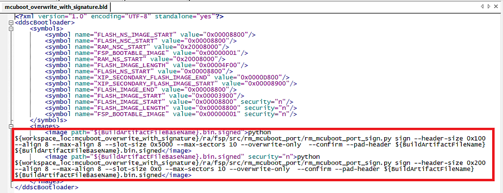
Just to clear things up, in Fig. 32 I opened the “.bld” file in another editor which supports word wrapping, so don’t be confused with different appearance.
The user’s application links to this “.bld” file using a special system variable (I’ll talk about it very soon), and every time when it’s built, the signing command is executed, producing the signed application image file.
Creation and Configuration of the User Application
As the user application we will create the simple Blinky project. I will skip the process of the project creation as it has been described in detail in tutorial 2. If you don’t want to read it, just create another C language based project with the “Bare Metal - Blinky” template and call it, to be explicit, “blinky_overwrite_with_signature”.
As you see the project creation doesn’t require any special options. So any application can be configured to be used with the bootloader. You just need to check the FW file size the same as we did it for the bootloader application (Fig. 24). This value, or better to say, the bigger value which is multiples of 0x800 should be written into the field “Image 1 Flash Area Size (Bytes)” (Fig. 7). But I’d recommend you to increase this value at least by 50% not to change it every time after you add some new code to your application.
Let’s now link our application to the bootloader’s “.bld” file in order to sign it and be able to load it with the MCUboot. To do this, we need to right click on the “blinky_overwrite_with_signature” in the Project Explorer, and in the drop-down menu select the last line “Properties”. In the left part of the opened window expand the “C/C++ Build” list and select the line “Build Variables” (Fig. 33).

In this window you also can read the description of what the build variables are and how they are used by the IDE.
Now let’s click the “Add…” button and add our own variable. The “Variable Name” should be “BootloaderDataFile”, the “Type” should be changed to “File”, and the value should be ${workspace_loc:<boot_project_name>}/Debug/<boot_project_name>.bld where <boot_project_name> is the project name of the bootloader application, in our case it’s “mcuboot_overwrite_with_signature”. Also set the checkbox “Apply to all configurations”. After everything, this window should look like Fig. 34.

Now you can click “OK” to return to the previous window. Make sure that a new variable has appeared in the list and click “Apply and Close”.
Now every time when you build this application, the MCUboot “.bld” file will be invoked, signing the user’s application image file. If we try to do this now, it will show the error (Fig. 35).
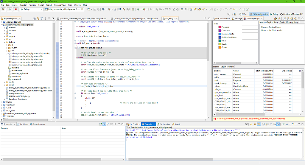
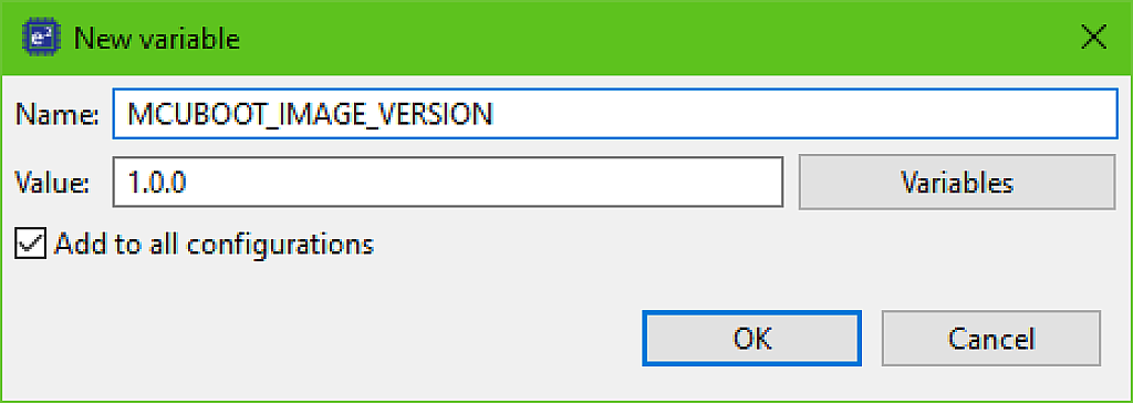
As you remember, when we configured the “MCUboot” block (Fig. 7), we enabled the downgrade prevention option, as well as “Validate Primary Image”. So we now need to define two environment variables (don’t mix them up with the build variables) MCUBOOT_IMAGE_VERSION which will contain the version number, and MCUBOOT_IMAGE_SIGNING_KEY which will contain the path to the signing key file path.
So, let’s open the “Properties” window again and select the line “Environment” in the left list (Fig. 36).

Click the “Add…” button and in the opened window write the “Name” field as “MCUBOOT_IMAGE_VERSION” and the “Value” field as “1.0.0”. Don’t forget to set the checkbox “Add to all configurations” (Fig. 37).
This file “root-ec-p256.pem” is the one of the example keys which we added to the “MCUboot” stack (Fig. 13). The other “.pem” files in this folder (Fig. 39) are the example keys for other signature types.

In real production conditions you should use your own keys. I will explain how to create the custom key in one of the next parts.
Now we can click “OK” to return to the “Properties” window but don’t hurry to close it. Let’s add the pre-build step to delete the “.elf” file in the same way as we did for the bootloader application (Fig. 23). Now we can click “Apply and close” to return to the main window.
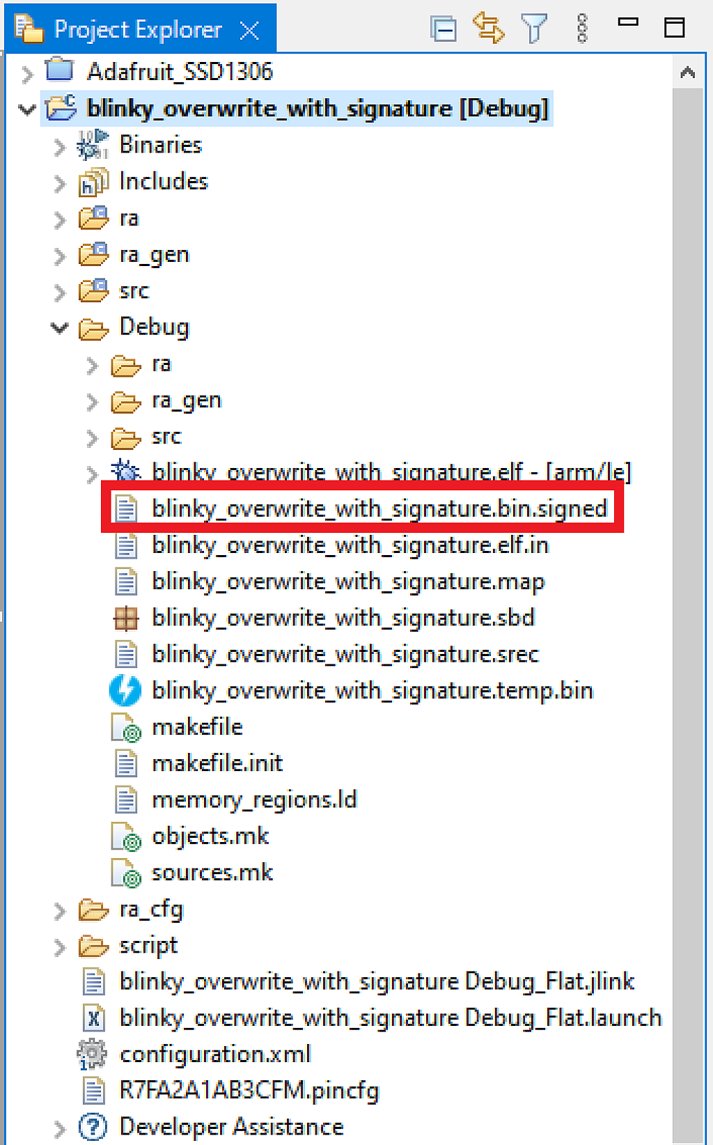
This is actually all we need to do to bind the user’s application with the bootloader application. Now we can build the “blinky_overwrite_with_signature” project and make sure there are now no errors. Also you can check that the application has been signed. You can see that by the appearance of the file “blinky_overwrite_with_signature.bin.signed” file in the “Debug” folder (Fig. 40).
Downloading the initial user’s application
Well, now the time has come for some practical work. So connect your board to the PC via the “DEBUG USB” connector. Loading the project using the bootloader is not that straightforward. The steps presented in this chapter can be used both for testing and for production.
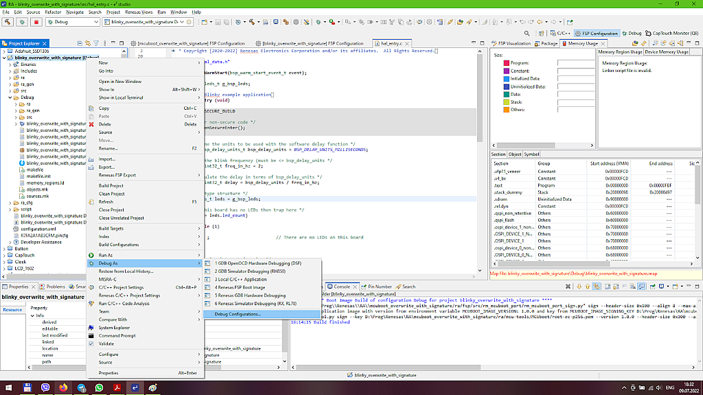
First we need to configure the debug configuration. To do this we need to right click on the user’s application project name in the Project Explorer and in the drop-down menu expand the list “Debug as” and select the last line “Debug Configurations…” (Fig. 41).
In the opened window go to the “Debugger” tab, then inside this tab open the tab “Debug Tool Settings”, scroll down to the option “Allow caching of flash contents” and change it from “Yes” to “No” (Fig. 42).

According to the J-Link User’s Guide, “If this checkbox is enabled, the flash contents are cached by J-Link to avoid reading data twice. This speeds up the transfer between debugger and target.” We disable this option, as otherwise the bootloader applications memory window information may show wrong information.
Now let’s switch to the “Startup” tab, and in the “Load image and symbols” field click the “Add…” button (Fig. 43).

In the opened window select “Workspace…” and find the “<boot_project_name>\Debug\<boot_project_name>.elf” file. In our case it’s the “mcuboot_overwrite_with_signature\Debug\mcuboot_overwrite_with_signature.elf” file (Fig. 44).

Then click the “OK” button to return to the previous window, where you should also click “OK”. In the “Load image and symbols” table change the Load type at the “Program binary” from “Image and symbols” to “Symbols only” (Fig. 45).

By doing this we tell the debugger to load the bootloader FW image into the flash memory instead of the user’s application image FW. But we leave symbols for both image files to let the debugger know the symbols (variables, functions names, etc.) of both projects.
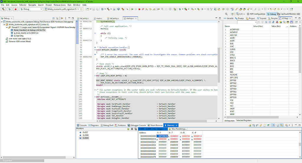
Now we can click the “Debug” button in the right bottom corner. The debugger will pause at the Reset_Handler function of the “startup.c” file. But when you move the mouse pointer to the file name you will see that it is located in the “mcuboot_overwrite_with_signature” folder (Fig. 46).

This means that according to our settings (Fig. 45) the bootloader application image has been downloaded to the MCU even though we’re only debugging the user’s application. Yeah, this is a bit of a paradox.
This paragraph is for the curious readers. You can check the memory content at every stage by opening the “Memory” window which can be found at the “Window” - “Show View” - “Memory” (Fig. 47).
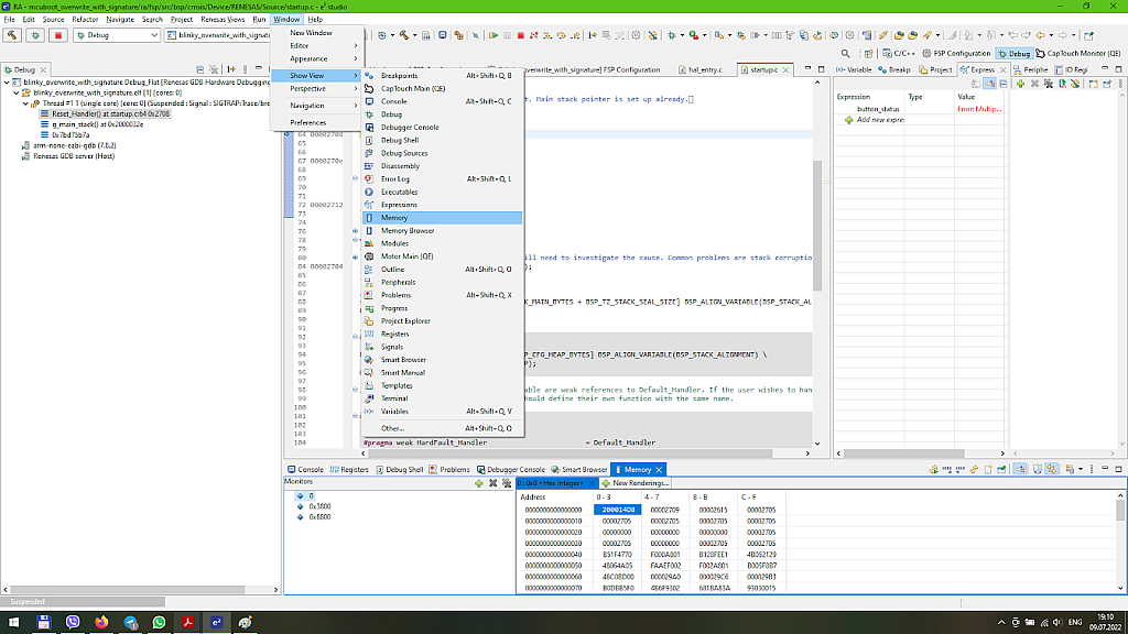
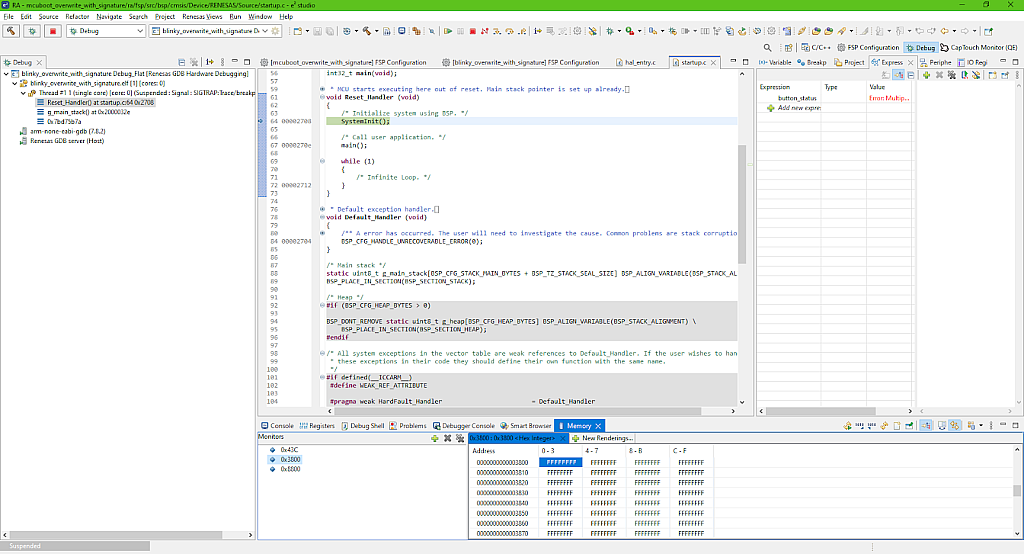
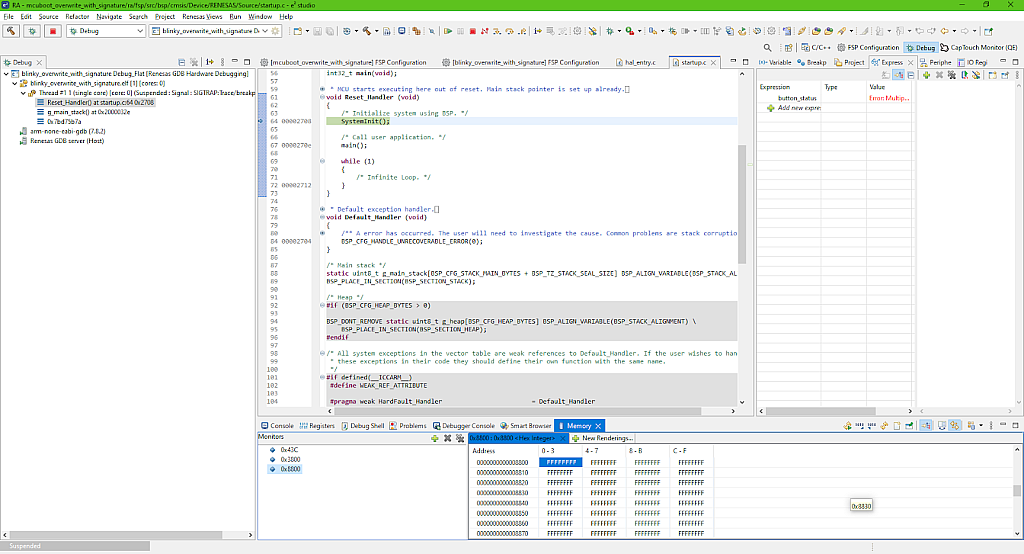
In the opened window click on the “+” sign at the “Monitors” part and add three addresses: 0x43C, 0x3800, and 0x8800. The first address corresponds to the bootloader location, the second address corresponds to the beginning of the primary slot, and the third address is the beginning of the secondary slot (Fig 48).

These addresses can be found in Fig. 7. and 19. The bootloader start address is the one that we set in the “fsp.ld” file - 0x43C. The primary slot address is the bootloader area size, which is 0x3800 in our case, and the secondary slot address is the sum of the bootloader areas size and the primary slot size which is 0x5000, so 0x3800 + 0x5000 = 0x8800. When you create your own application, take this into account.
So in Fig. 48 you can see the beginning of the flash memory where the bootloader image is located, and it’s not empty (the memory content differs from 0xFFFFFFFF). You can make sure that the primary and secondary slots are both empty (Fig. 49, 50).
OK, now that the “out of curiosity” section is finished, let’s move forward.
We now need to download the user’s application to the address 0x3800. To do this we need to click the button “Load Ancillary File” in the toolbar (Fig. 51).

In the opened window select “Workspace” and find the “blinky_overwrite_with_signature\Debug\blinky_overwrite_with_signature.bin.signed” file. Set the checkbox “Load as raw binary image” and change the “Address” field to 0x3800 (Fig. 52).
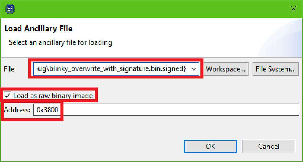
Then click the “OK” button to download the image file. Please note that the file is copied to the memory as is, without any changes. so if it is faulty, it still will be copied, there is no validation at this step.
You can now open the “Memory” window again at address 0x3800 and make sure that its content has been changed (Fig. 53).
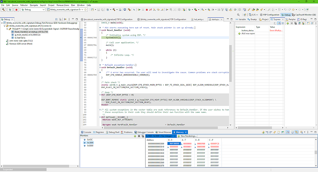
The secondary slot is still empty the same as in Fig. 50, you can make sure of this by yourself.
OK, now the bootloader and user’s application are both downloaded, let’s now click on the “Resume” button
to run the project (you may need to click it twice as we usually do). And finally, after all these steps and struggles we can see… the blinking LED. Ta-da!
Let’s briefly consider once again what just happened. We downloaded the bootloader application instead of the user’s application when we started the debugging of the last one. Then, prior to running the bootloader we downloaded the signed user’s application as “Ancillary file” to the location started with the address 0x3800. When we click the “Resume” button, the bootloader checks the secondary slot first to see if there is a new application. In our case it’s absent, so the bootloader checks and validates the image in the primary slot. If the verification process has passed successfully, the bootloader reloads the stack pointer, the interrupts vector, and the program counter to pass the control to the user’s application and steps aside till the next MCU reset.
So, as you see, a lot of things happen between the startup and the LED blinking starting. This is the initial state for the MCUboot in the Overwrite mode (see table 1): we have the running application in the primary slot, and the bootloader in its own slot.
Downloading the new application
Let’s now change the user’s application and download it to the secondary slot to see how the bootloader manages it.
So let’s stop the debugging, then open the “hal_entry.c” file of the “blinky_overwrite_with_signature” project and in line 45 change the value of the freq_in_hz variable from 2 to 4 (fig 54). Thus the LED in the new application will blink twice faster than in the previous one.
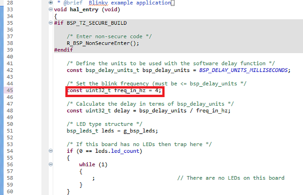
Then build the project and start the debugging process the same as we did before up to the step presented in Fig. 46. At this point you can check the memory content like we did before and make sure that it is the same as before in all three slots. Now let’s click on the “Load Ancillary file” again (Fig. 51) and load the same “blinky_overwrite_with_signature\Debug\blinky_overwrite_with_signature.bin.signed” file (which is now modified to have double the frequency) but this time, the address to download should be 0x8800 as we now are filling the secondary slot (Fig. 56).

Press the “OK” button to download the image. Now, if you check the content of the secondary slot, you can see that it is not empty anymore (Fig. 57).
Let’s now click the “Resume” button and see what happens. Now the booting process takes more time as the bootloader checks the secondary slot first, then copies it to the primary slot, then erases the secondary slot, and finally runs the application in the primary slot. After all these steps you can see that the LED is blinking with a frequency two times higher than initially.
If you pause the debugging and check the memory content again, you can see that the primary slot (Fig. 58) has now the same content as the secondary slot before booting (Fig. 57), and that the secondary slot is empty (Fig. 59).
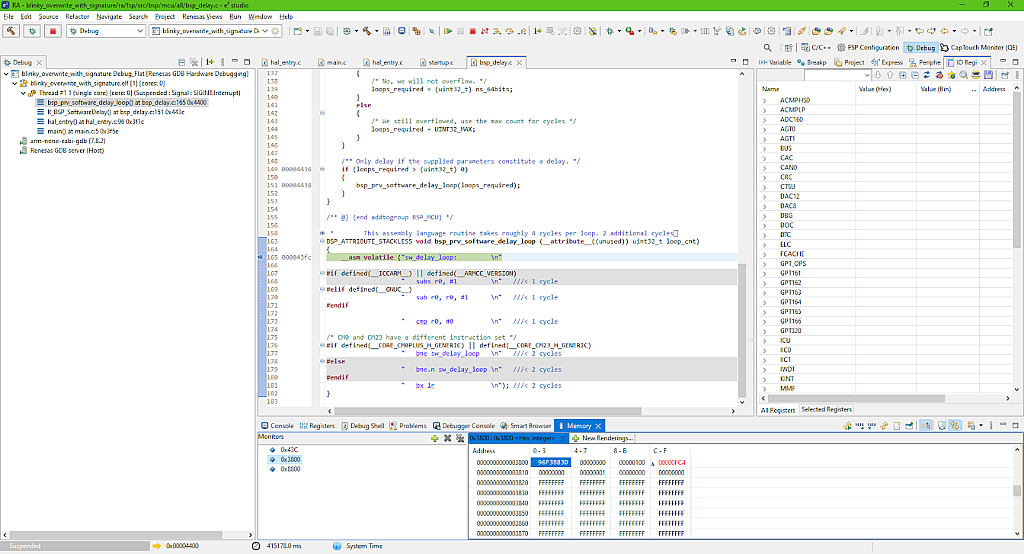
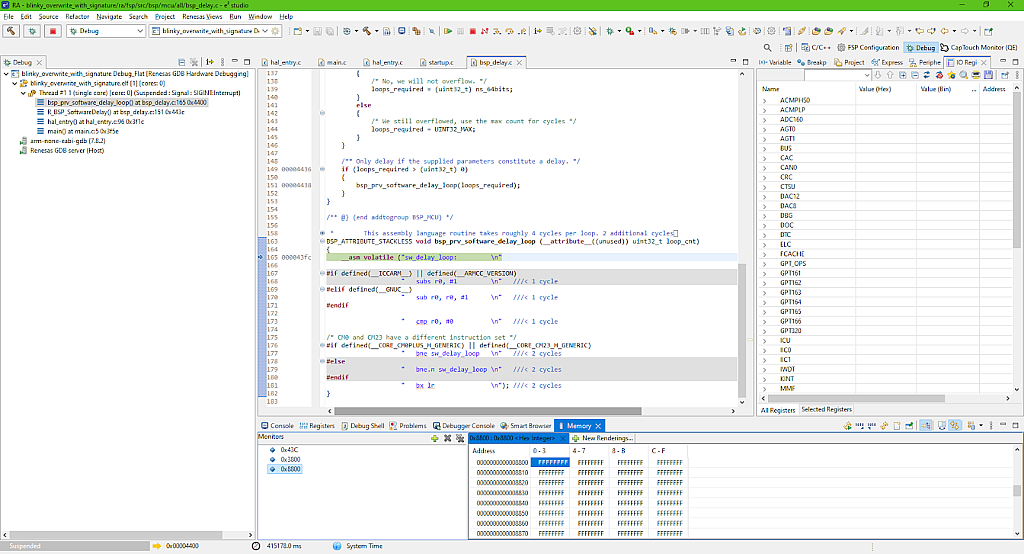
It should be mentioned here that in real conditions, the process of downloading the new application into the secondary slot lays upon the user’s application. It should have some interface (UART, USB, SD-card or other) to get the new image and save it into the correct flash memory area.
Attempts to ruin the new application image
Let’s try to spoil the application image and see how the MCUboot manages with these situations. First, let’s open the “hal_entry.c” file of the “blinky_overwrite_with_signature” project again and restore the initial value of the freq_in_hz variable from 4 to 2. So now if the application is updated, we will see the LED blinking twice slower than the current frequency.
So let’s build the “blinky_overwrite_with_signature” project once again and start its debugging, then download the image file to the secondary slot as we did before (Fig. 56). Now let’s open the “Memory” window at the secondary slot then double click on any value and make some change (Fig. 57).

Let’s now click the “Resume” button and see what happens. Now the booting process takes more time as the bootloader checks the secondary slot first, then copies it to the primary slot, then erases the secondary slot, and finally runs the application in the primary slot. After all these steps you can see that the LED is blinking with a frequency two times higher than initially.
If you pause the debugging and check the memory content again, you can see that the primary slot (Fig. 58) has now the same content as the secondary slot before booting (Fig. 57), and that the secondary slot is empty (Fig. 59).


It should be mentioned here that in real conditions, the process of downloading the new application into the secondary slot lays upon the user’s application. It should have some interface (UART, USB, SD-card or other) to get the new image and save it into the correct flash memory area.
Attempts to ruin the new application image
Let’s try to spoil the application image and see how the MCUboot manages with these situations. First, let’s open the “hal_entry.c” file of the “blinky_overwrite_with_signature” project again and restore the initial value of the freq_in_hz variable from 4 to 2. So now if the application is updated, we will see the LED blinking twice slower than the current frequency.
So let’s build the “blinky_overwrite_with_signature” project once again and start its debugging, then download the image file to the secondary slot as we did before (Fig. 56). Now let’s open the “Memory” window at the secondary slot then double click on any value and make some change (Fig. 57).

As you see in Fig. 60, I’ve changed a single bit at the address 0x8830 - replacing the last number with “E”. In this way we imitate a flash memory error or error while downloading the image into the memory. The MCUboot should check the integrity of the image and reject it if something is wrong with it. Let’s check if it’s so, and click the “Resume” button to run the bootloader.
After a few seconds you will see that the LED is still blinking fast, which means that the new image hasn’t been downloaded. So how does the bootloader manage this? During the signing process the hash of the image file is calculated, and then this hash is stored in the image header (see Fig. 7). When the bootloader starts, it calculates the hash and compares it with the one loaded into the header. If they don’t match, the image is rejected.
Let’s now see how bootloader prevents the version downgrade. Let’s open the properties of the “blinky_overwrite_with_signature” project, select the “C/C++ Build” - “Environment” line, and change the MCUBOOT_IMAGE_VERSION variable from 1.0.0 to 0.9.0 (Fig. 61).

Now click “OK”, then “Apply and Close”. Then do the same steps as before - build and debug the application, and load the new image to the secondary slot. Now let’s click on the “Resume” button and see what happens.
The LED still is blinking fast. This is because we have enabled the “Downgrade Prevention” option (Fig. 7). If we didn’t do this then the application would be upgraded without any problems.
Also, MCUboot can recognize if the user’s application image has been signed with the wrong key and also reject it in this case. Unfortunately I don’t have any other key now to test this, but we will return to this experiment in one of the next parts when I will talk about the creation of custom keys.
And that’s it for now, this tutorial is really large and meaty, and even though I expected it to be like this, you need some time to understand how this all works. So let’s stop at this point. In the next part I will talk about working the bootloader in the Swap and Direct XIP modes and their peculiarities.
As homework I suggest you try to download one of our previous applications using the MCUboot, for example the one with the 1602 or OLED displays. In this case you can display the version numbers and be sure what application is running now.

Get the latest tools and tutorials, fresh from the toaster.


