Have you ever noticed how smooth an elevator moves? It is the beauty of a DC compound motor’s characteristics. Almost all old electric locomotives employed DC series motors to provide the required traction. DC motors come in different forms making it possible to suit the load demands by choosing a best fit among the available variants. Let’s understand the different types of DC motors, their characteristics, and applications in detail.
In a DC motor, the field winding produces the required magnetic flux. The armature draws current from the supply and this current flows through the armature, interacting with the field flux and producing the motoring action. Naturally, both the armature and the field winding need to be energised from the supply. Based on the way these two windings are connected, either in series or parallel, DC motors can be classified as DC series motor and DC shunt motor.
Before dealing with the motor characteristics, let's review some basic DC motor principles.
Consider the DC motor shown in the image below.
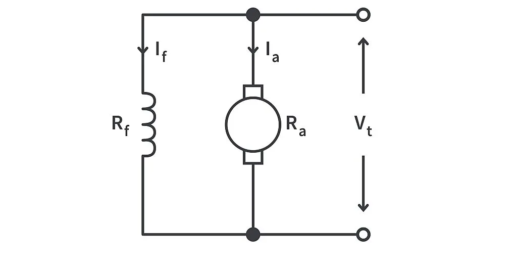
The speed (N) and torque (T) of the motor can be related to various parameters of the motor with the help of the equations below:


where,
Vt is the terminal voltage of the supply
Ia the armature current
Ra the armature circuit resistance
K is a constant.
Φ is the field flux available
(Note: The magnetic flux produced by a winding is directly proportional to the current flowing through it. In the DC motor described in the image above, field flux Φ produced by the shunt winding is directly proportional to the field current If (Φ α If))
The above equations tell us that the speed is inversely proportional to the field flux and that the torque is directly proportional to the product of armature current Ia and field flux Φ. In other words, speed is greater when there is lower field flux. The torque (basically force at an angle) on the other hand is greater when there’s more field flux (which depends on the current through the field winding) and more armature current (which occurs when there's more load).
The motor in the image just described is a DC shunt motor – the field winding appears in parallel (shunt) across the armature winding. The shunt field current If remains constant meaning the flux can also be assumed to be almost constant. The IaRa drop even at full loads is about 5%. The speed now depends just on Vt which is fixed. Hence speed vs Ia (load) characteristics is almost flat. The flux being constant, the torque now is proportional only to the armature current – increasing almost linearly with Ia. Both the speed vs Ia and speed vs torque characteristics of the shunt motor are shown in the image below.
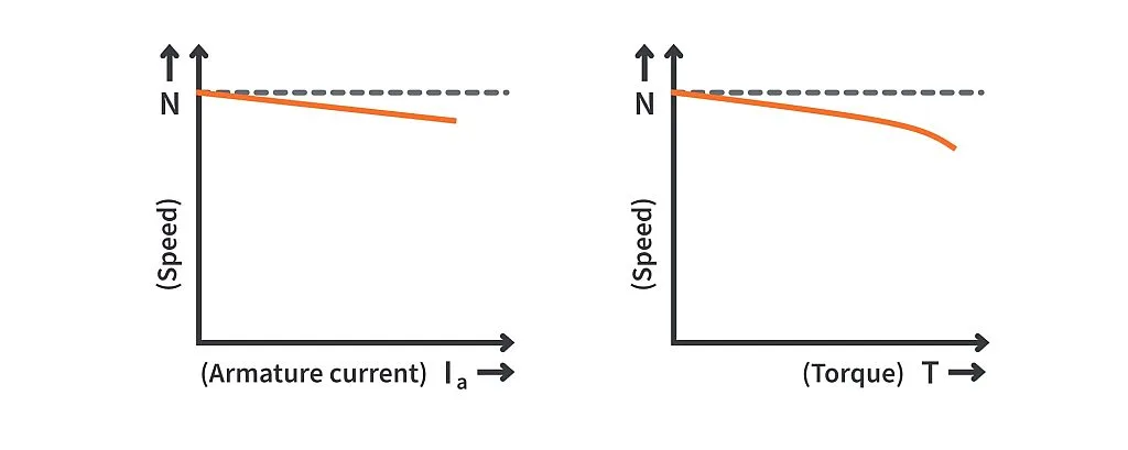
As can be seen from the performance characteristics above, the shunt motor is a constant speed motor and is extensively used in rolling mills, centrifugal pumps, and lathe machines.
In separately excited DC motors, the field winding can be excited from a different source of supply altogether. The characteristics of a separately excited DC motor are like that of a DC shunt motor but with an added advantage that the field current can be varied by varying the excitation of the field winding. This allows for speed control of the motor from both the armature and field side. The separately excited motors are used in applications requiring a wide range of speed variations. A permanent magnet DC (PMDC) motor is also an example of a separately excited DC motor. PMDC motors are manufactured in millions each year and can be found in applications varying from electric toothbrushes and toy cars to automobiles, blowers, and air conditioners.
The image given below is that of a series motor. In a series motor both the armature and field winding are connected in series with each other.
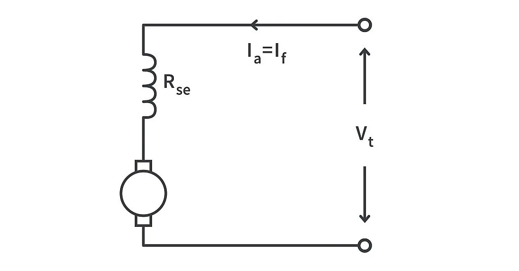
The flux Φ which is proportional to If (= Ia in series motor) increases as Ia increases. The speed being inversely proportional to Φ – decreases with increase in load. The torque in series motors will be proportional to Ia squared. The speed versus load characteristics of a series motor can be seen in the image below:
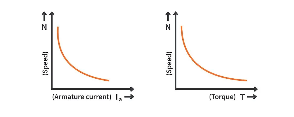
At low values of Ia (less load), the field flux is also less. The speed which is inversely proportional to the field flux can increase to dangerous values – a series motor should never be started on zero or light load. It can also be noticed from the characteristics that at low speeds, the torque is high in a series motor. This characteristic of a series motor makes it best suited for traction loads where high starting torque is necessary. Until recent advancements in AC motors, almost all traction applications employed the DC series motor.
Another type of DC motor is the DC compound motor which has both a shunt and a series winding. The series field flux can be made to oppose (differentially compounded DC motor) or support the shunt field flux (cumulatively compounded DC motor). The former is rarely used hence we will limit our discussion only to the cumulatively compounded DC motors. The circuit of a cumulatively compounded DC motor and its performance characteristics is shown in the image below:
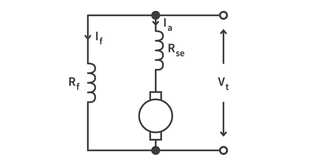
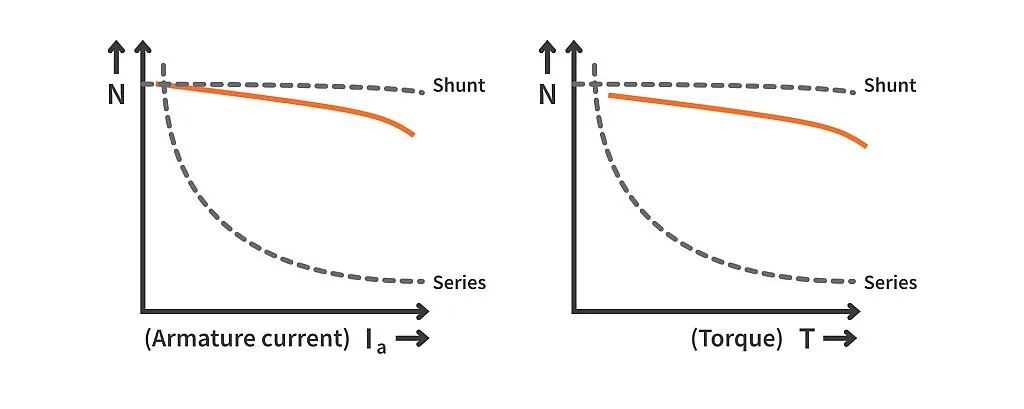
Cumulatively compounded DC motors make use of the best of both series and shunt motors. In this motor, the shunt field flux remains constant as If depends only on Vt which is fixed. The series field flux depends on the series field current which is also the armature current Ia. As Ia increases with an increase in mechanical load on the motor, the series field flux, which is proportional to the armature current, will also increase with load. This flux produced from the series winding adds to the shunt field flux. Hence, the overall flux increases with load. This increase in flux with load ensures good motor torque even at increased loads like in a shunt motor. The shunt field flux of the compound motor maintains enough flux at starting to guarantee a safe no-load operating speed unlike the DC series motor. Cumulatively compounded DC motors are used extensively in elevators, rolling mills and shears.
Control of DC motors is easy. However, their main disadvantage is the wear of brushes and sparking of commutators. Until advancements in VLSI and power electronics, DC motors had dominated the industry over AC motors. Nowadays, slip ring induction motors have replaced DC shunt motors. The permanent magnet synchronous motors are employed for traction purposes instead of DC series motors. PMDC motors and separately excited motors on the other hand, still play a prominent role in many applications.


