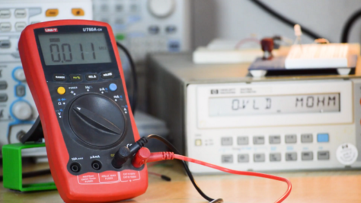
Continuity testing is one of the most basic tests to perform while troubleshooting a circuit. It simply is a test to see whether two points of interest are electrically connected. On your typical DMM (Digital Multimeter), the continuity setting looks like a speaker or sound wave. What the DMM does at this setting is send a small current through the probes. If the current flows from one probe, through the circuit under test, and the to the second probe, there is continuity. The DMM will give a tone to indicate continuity. On some DMMs this function is also the resistance test. Common uses for this test are to check if your power and ground are shorted, testing operation of switches, checking that long runs of wire are broken, and checking for shorts (commonly solder bridges) between pads/legs/traces on a PCB.
1) Select Continuity Test mode (pic/graphic?) on your DMM. It may be the same mode as resistance (Ω) testing.
2) Make sure the black probe is plugged into the COM jack.
3) Make sure the red probe is plugged into the V/Ω jack.
4) The DMM beeps if continuity is detected. A good step before testing the circuit is to touch the probes together to test that you’re in the right mode and plugged into the correct jacks; it also will familiarize you with the beep. If the circuit or component is open, there will be no beep.
5) As always when working with circuits, power off the device or circuit you're testing. Touch the probes to the test points or across the the component being tested. Take into account that the circuit might have other paths that affect your reading so if you can, isolate the component from the rest of the circuit.
6) Many DMMs have an auto-off feature but make sure to turn the DMM off and store the probes to take care of that super useful DMM.


