Encoder
An encoder is a circuit that changes a set of signals into a code. Let's begin making a 2-to-1 line encoder truth table by reversing the 1-to-2 decoder truth table.

This truth table is a little short. A complete truth table would be

One question we need to answer is what to do with those other inputs? Do we ignore them? Do we have them generate an additional error output? In many circuits this problem is solved by adding sequential logic in order to know not just what input is active but also which order the inputs became active.
A more useful application of combinational encoder design is a binary to 7-segment encoder. The seven segments are given according

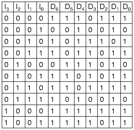
Our truth table is:
Deciding what to do with the remaining six entries of the truth table is easier with this circuit. This circuit should not be expected to encode an undefined combination of inputs, so we can leave them as "don't care" when we design the circuit. The equations were simplified with karnaugh maps.


The collection of equations is summarised here:

The circuit is:

And the corresponding ladder diagram:

Lessons In Electric Circuits copyright (C) 2000-2020 Tony R. Kuphaldt, under the terms and conditions of the CC BY License.
See the Design Science License (Appendix 3) for details regarding copying and distribution.
Revised November 06, 2021
Explore CircuitBread


Get the latest tools and tutorials, fresh from the toaster.


