Vacuum Tube Audio Amplifier
Parts and Materials
- One 12AX7 dual triode vacuum tube
- Two power transformers, 120VAC step-down to 12VAC (Radio Shack catalog # 273-1365, 273-1352, or 273-1511).
- Bridge rectifier module (Radio Shack catalog # 276-1173)
- Electrolytic capacitor, at least 47 µF, with a working voltage of at least 200 volts DC.
- Automotive ignition coil
- Audio speaker, 8 Ω impedance
- Two 100 kΩ resistors
- One 0.1 µF capacitor, 250 WVDC (Radio Shack catalog # 272-1053)
- "Low-voltage AC power supply" as shown in AC Experiments chapter
- One toggle switch, SPST ("Single-Pole, Single-Throw")
- Radio, tape player, musical keyboard, or other source of audio voltage signal
Where can you obtain a 12AX7 tube, you ask? These tubes are very popular for use in the "preamplifier" stages of many professional electric guitar amplifiers. Go to any good music store and you will find them available for a modest price ($12 US or less). A Russian manufacturer named Sovtek makes these tubes new, so you need not rely on "New-Old-Stock" (NOS) components left over from defunct American manufacturers. This model of tube was very popular in its day, and may be found in old "tubed" electronic test equipment (oscilloscopes, oscillators), if you happen to have access to such equipment. However, I strongly suggest buying a tube new rather than taking chances with tubes salvaged from antique equipment.
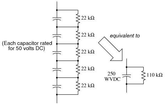
It is important to select an electrolytic capacitor with sufficient working voltage (WVDC) to withstand the output of this amplifier's power supply circuit (about 170 volts). I strongly recommend choosing a capacitor with a voltage rating well in excess of the expected operating voltage, so as to handle unexpected voltage surges or any other event that may tax the capacitor. I purchased the Radio Shack electrolytic capacitor assortment (catalog # 272-802), and it happened to contain two 47 µF, 250 WVDC capacitors. If you are not as fortunate, you may build this circuit using five capacitors, each rated at 50 WVDC, to substitute for one 250 WVDC unit:

Bear in mind that the total capacitance for this five-capacitor network will be 1/5, or 20%, of each capacitor's value. Also, to ensure even charging of capacitors in the network, be sure all capacitor values (in µF) and all resistor values are identical.
An automotive ignition coil is a special-purpose high-voltage transformer used in car engines to produce tens of thousands of volts to "fire" the spark plugs. In this experiment, it is used (very unconventionally, I might add!) as an impedance-matching transformer between the vacuum tube and an 8 Ω audio speaker. The specific choice of "coil" is not critical, so long as it is in good operating condition. Here is a photograph of the coil I used for this experiment:

The audio speaker need not be extravagant. I've used small "bookshelf" speakers, automotive (6"x9") speakers, as well as a large (100 watt) 3-way stereo speaker for this experiment, and they all work fine. Do not use a set of headphones under any circumstances, as the ignition coil does not provide electrical isolation between the 170 volts DC of the "plate" power supply and the speaker, thus elevating the speaker connections to that voltage with respect to ground. Since obviously placing wires on your head with high voltage to ground would be very hazardous, please do not use headphones!
You will need some source of audio-frequency AC as an input signal to this amplifier circuit. I recommend a small battery-powered radio or musical keyboard, with an appropriate cable plugged into the "headphone" or "audio out" jack to convey the signal to your amplifier.
Cross-references
Lessons In Electric Circuits, Volume 3, chapter 13: "Electron Tubes"
Lessons In Electric Circuits, Volume 3, chapter 3: "Diodes and Rectifiers"
Lessons In Electric Circuits, Volume 2, chapter 9: "Transformers"
Learning Objectives
- Using a vacuum tube (triode) as an audio amplifier
- Using transformers in both step-down and step-up operation
- How to build a high-voltage DC power supply
- Using a transformer to match impedances
Schematic Diagram


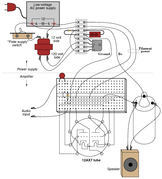
Illustration

Instructions
Welcome to the world of vacuum tube electronics! While not exactly an application of semiconductor technology (power supply rectifier excepted), this circuit is useful as an introduction to vacuum tube technology, and an interesting application for impedance-matching transformers. It should be noted that building and operating this circuit involves work with lethal voltages! You must exhibit the utmost care while working with this circuit, as 170 volts DC is capable of electrocuting you!! It is recommended that beginners seek qualified assistance (experienced electricians, electronics technicians, or engineers) if attempting to build this amplifier.
WARNING: do not touch any wires or terminals while the amplifier circuit is energized! If you must make contact with the circuit at any point, turn off the "plate" power supply switch and wait for the filter capacitor to discharge below 30 volts before touching any part of the circuit. If testing circuit voltages with the power on, use only one hand if possible to avoid the possibility of an arm-to-arm electric shock.
Building the high-voltage power supply
Vacuum tubes require fairly high DC voltage applied between plate and cathode terminals in order to function efficiently. Although it is possible to operate the amplifier circuit described in this experiment on as low as 24 volts DC, the power output will be miniscule and the sound quality poor. The 12AX7 triode is rated at a maximum "plate voltage" (voltage applied between plate and cathode terminals) of 330 volts, so our power supply of 170 volts DC specified here is well within that maximum limit. I've operated this amplifier on as high as 235 volts DC, and discovered that both sound quality and intensity improved slightly, but not enough in my estimation to warrant the additional hazard to experimenters.
The power supply actually has two different power outputs: the "B+" DC output for plate power, and the "filament" power, which is only 12 volts AC. Tubes require power applied to a small filament (sometimes called a heater) in order to function, as the cathode must be hot enough to thermally emit electrons, and that doesn't happen at room temperature! Using one power transformer to step household 120 volt AC power down to 12 volts AC provides low-voltage for the filaments, and another transformer connected in step-up fashion brings the voltage back up to 120 volts. You might be wondering, "why step the voltage back up to 120 volts with another transformer? Why not just tap off the wall socket plug to obtain 120 volt AC power directly, and then rectify that into 170 volts DC?" The answer to this is twofold: first, running power through two transformers inherently limits the amount of current that may be sent into an accidental short-circuit on the plate-side of the amplifier circuit. Second, it electrically isolates the plate circuit from the wiring system of your house. If we were to rectify wall-socket power with a diode bridge, it would make both DC terminals (+ and -) elevated in voltage from the safety ground connection of your house's electrical system, thereby increasing the shock hazard.
Note the toggle switch connected between the 12-volt windings of the two transformers, labeled "Plate supply switch." This switch controls power to the step-up transformer, thereby controlling plate voltage to the amplifier circuit. Why not just use the main power switch connected to the 120 volt plug? Why have a second switch to shut off the DC high voltage, when shutting off one main switch would accomplish the same thing? The answer lies in proper vacuum tube operation: like incandescent light bulbs, vacuum tubes "wear" when their filaments are powered up and down repeatedly, so having this additional switch in the circuit allows you to shut off the DC high voltage (for safety when modifying or adjusting the circuit) without having to shut off the filament. Also, it is a good habit to wait for the tube to reach full operating temperature before applying plate voltage, and this second switch allows you to delay the application of plate voltage until the tube has had time to reach operating temperature.
During operation, you should have a voltmeter connected to the "B+" output of the power supply (between the B+ terminal and ground), continuously providing indication of the power supply voltage. This meter will show you when the filter capacitor has discharged below the shock-hazard limit (30 volts) when you turn off the "Plate supply switch" to service the amplifier circuit.
The "ground" terminal shown on the DC output of the power supply circuit need not connect to earth ground. Rather, it is merely a symbol showing a common connection with a corresponding ground terminal symbol in the amplifier circuit. In the circuit you build, there will be a piece of wire connecting these two "ground" points together. As always, the designation of certain common points in a circuit by means of a shared symbol is standard practice in electronic schematics.
You will note that the schematic diagram shows a 100 kΩ resistor in parallel with the filter capacitor. This resistor is quite necessary, as it provides the capacitor a path for discharge when the AC power is turned off. Without this "bleeder" resistor in the circuit, the capacitor would likely retain a dangerous charge for a long time after "power-down," posing an additional shock hazard to you. In the circuit I built -- with a 47 µF capacitor and a 100 kΩ bleeder resistor -- the time constant of this RC circuit was a brief 4.7 seconds. If you happen to find a larger filter capacitor value (good for minimizing unwanted power supply "hum" in the speaker), you will need to use a correspondingly smaller value of bleeder resistor, or wait longer for the voltage to bleed off each time you turn the "Plate supply" switch off.
Be sure you have the power supply safely constructed and working reliably before attempting to power the amplifier circuit with it. This is good circuit-building practice in general: build and troubleshoot the power supply first, then build the circuit you intend to power with it. If the power supply does not function as it should, then neither will the powered circuit, no matter how well it may be designed and built.
Building the amplifier
One of the problems with building vacuum tube circuits in the 21st century is that sockets for these components can be difficult to find. Given the limited lifetime of most "receiver" tubes (a few years), most "tubed" electronic devices used sockets for mounting the tubes, so that they could be easily removed and replaced. Though tubes may still be obtained (from music supply stores) with relative ease, the sockets they plug into are considerably scarcer -- your local Radio Shack will not have them in stock! How, then, do we build circuits with tubes, if we might not be able to obtain sockets for them to plug in to?
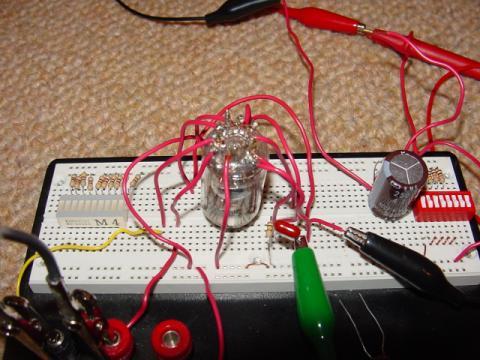
For small tubes, this problem may be circumvented by directly soldering short lengths of 22-gauge solid copper wire to the pins of the tube, thus enabling you to "plug" the tube into a solderless breadboard. Here is a photograph of my tube amplifier, showing the 12AX7 in an inverted position (pin-side-up). Please disregard the 10-segment LED bargraph to the left and the 8-position DIP switch assembly to the right in the photograph, as these are leftover components from a digital circuit experiment assembled previously on my breadboard.

One benefit of mounting the tube in this position is ease of pin identification, since most "pin connection diagrams" for tubes are shown from a bottom view:

You will notice on the amplifier schematic that both triode elements inside the 12AX7's glass envelope are being used, in parallel: plate connected to plate, grid connected to grid, and cathode connected to cathode. This is done to maximize power output from the tube, but it is not necessary for demonstrating basic operation. You may use just one of the triodes, for simplicity, if you wish.
The 0.1 µF capacitor shown on the schematic "couples" the audio signal source (radio, musical keyboard, etc.) to the tube's grid(s), allowing AC to pass but blocking DC. The 100 kΩ resistor ensures that the average DC voltage between grid and cathode is zero, and cannot "float" to some high level. Typically, bias circuits are used to keep the grid slightly negative with respect to ground, but for this purpose a bias circuit would introduce more complexity than its worth.
When I tested my amplifier circuit, I used the output of a radio receiver, and later the output of a compact disk (CD) player, as the audio signal source. Using a "mono"-to-"phono" connector extension cord plugged into the headphone jack of the receiver/CD player, and alligator clip jumper wires connecting the "mono" tip of the cord to the input terminals of the tube amplifier, I was able to easily send the amplifier audio signals of varying amplitude to test its performance over a wide range of conditions:

A transformer is essential at the output of the amplifier circuit for "matching" the impedances of vacuum tube and speaker. Since the vacuum tube is a high-voltage, low-current device, and most speakers are low-voltage, high-current devices, the mismatch between them would result in very audio low power output if they were directly connected. To successfully match the high-voltage, low-current source to the low-voltage, high current load, we must use a step-down transformer.
Since the vacuum tube circuit's Thevenin resistance ranges in the tens of thousands of ohms, and the speaker only has about 8 ohms impedance, we will need a transformer with an impedance ratio of about 10,000:1. Since the impedance ratio of a transformer is the square of its turns ratio (or voltage ratio), we're looking for a transformer with a turns ratio of about 100:1. A typical automotive ignition coil has approximately this turns ratio, and it is also rated for extremely high voltage on the high-voltage winding, making it well suited for this application.
The only bad aspect of using an ignition coil is that it provides no electrical isolation between primary and secondary windings, since the device is actually an autotransformer, with each winding sharing a common terminal at one end. This means that the speaker wires will be at a high DC voltage with respect to circuit ground. So long as we know this, and avoid touching those wires during operation, there will be no problem. Ideally, though, the transformer would provide complete isolation as well as impedance matching, and the speaker wires would be perfectly safe to touch during use.
Remember, make all connections in the circuit with the power turned off! After checking connections visually and with an ohmmeter to ensure that the circuit is built as per the schematic diagram, apply power to the filaments of the tube and wait about 30 seconds for it to reach operating temperature. The both filaments should emit a soft, orange glow, visible from both the top and bottom views of the tube.
Turn the volume control of your radio/CD player/musical keyboard signal source to minimum, then turn on the plate supply switch. The voltmeter you have connected between the power supply's B+ output terminal and "ground" should register full voltage (about 170 volts). Now, increase the volume control on the signal source and listen to the speaker. If all is well, you should hear the correct sounds clearly through the speaker.
Troubleshooting this circuit is best done with the sensitive audio detector described in the DC and AC chapters of this Experiments volume. Connect a 0.1 µF capacitor in series with each test lead to block DC from the detector, then connect one of the test leads to ground, while using the other test lead to check for audio signal at various points in the circuit. Use capacitors with a high voltage rating, like the one used on the input of the amplifier circuit:

Using two coupling capacitors instead of just one adds an additional degree of safety, in helping to isolate the unit from any (high) DC voltage. Even without the extra capacitor, though, the detector's internal transformer should provide sufficient electrical isolation for your safety in using it to test for signals in a high-voltage circuit like this, especially if you built your detector using a 120 volt power transformer (rather than an "audio output" transformer) as suggested. Use it to test for a good signal at the input, then at the grid pin(s) of the tube, then at the plate of the tube, etc. until the problem is found. Being capacitively coupled, the detector is also able to test for excessive power supply "hum:" touch the free test lead to the supply's B+ terminal and listen for a loud 60 Hz humming noise. The noise should be very soft, not loud. If it is loud, the power supply is not filtered adequately enough, and may need additional filter capacitance.
After testing a point in the amplifier circuit with large DC voltage to ground, the coupling capacitors on the detector may build up substantial voltage. To discharge this voltage, briefly touch the free test lead to the grounded test lead. A "pop" sound should be heard in the headphones as the coupling capacitors discharge.
If you would rather use a voltmeter to test for the presence of audio signal, you may do so, setting it to a sensitive AC voltage range. The indication you get from a voltmeter, though, doesn't tell you anything about the quality of the signal, just its mere presence. Bear in mind that most AC voltmeters will register a transient voltage when initially connected across a source of DC voltage, so don't be surprised to see a "spike" (a strong, momentary voltage indication) at the very moment contact is made with the meter's probes to the circuit, rapidly decreasing to the true AC signal value.
You may be pleasantly surprised at the quality and depth of tone from this little amplifier circuit, especially given its low power output: less than 1 watt of audio power. Of course, the circuit is quite crude and sacrifices quality for simplicity and parts availability, but it serves to demonstrate the basic principle of vacuum tube amplification. Advanced hobbyists and students may wish to experiment with biasing networks, negative feedback, different output transformers, different power supply voltages, and even different tubes, to obtain more power and/or better sound quality.
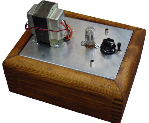
Here is a photo of a very similar amplifier circuit, built by the husband-and-wife team of Terry and Cheryl Goetz, illustrating what can be done when care and craftsmanship are applied to a project like this.

Lessons In Electric Circuits copyright (C) 2000-2020 Tony R. Kuphaldt, under the terms and conditions of the CC BY License.
See the Design Science License (Appendix 3) for details regarding copying and distribution.
Revised January 18, 2010
Explore CircuitBread

Get the latest tools and tutorials, fresh from the toaster.


