How to Solve Complicated Circuits with Kirchhoff's Voltage Law (KVL)?
Published
We have gone over Kirchhoff’s Current Law (KCL) in a previous tutorial and Kirchhoff’s Voltage Law (KVL) is very similar but focused on the voltage in a circuit, not the current. Kirchhoff’s Voltage law states that the sum of the voltages in a closed loop will equal zero. In other words, if you look at any loop that goes completely all the way around, any increases in voltage throughout the loop will be offset with an equal amount of decreases in voltage. Visually, this can be seen in the image below.

Using this concept, much as how we can use nodal analysis with KCL, we can use mesh analysis because of KVL. While a mesh is basically any loop within a circuit, for mesh analysis, we will need to define meshes that don’t enclose any other meshes.

You can see that if we make a loop around the ‘outside’ of the entire circuit, technically it is a mesh because the loop can be completed. However, for purposes of analysis, we need to break it into three different meshes. So let’s go over the steps of how to solve a circuit using mesh analysis before jumping into a few examples.
There are 5 steps that we recommend, and as we did with the KCL/nodal analysis steps, two of the steps are to calm down and step back, making sure that everything makes sense intuitively.
- Take your time, breathe, and assess the problem. Write down what info you’ve been given and any intuitive insights you have.
- Assign mesh currents to all of the meshes. There should be one current assigned per mesh. You need to choose which direction your current is flowing - this is semi-arbitrary because as long as you do your math right, it doesn’t really matter. But in most cases, people assume a clockwise current direction.
- Apply KVL to each of the meshes, using Ohm’s Law to show the voltages in terms of the current.
- Solve the simultaneous equations (like we did with KCL) to find the actual values.
- Sanity check. Take a moment to review what you’ve done and see if the numbers make sense and are internally consistent.
We’ll go over some examples now and frankly, after these examples, the only real additions and changes will be complications that make the math more difficult. The problems shouldn’t get much harder conceptually but the math can get significantly harder. Please, don’t get lost in the math. If the numbers start to lose their numbers, make sure to come up for air and remember what you’re doing and what you’re trying to do.
Example 1

A simple example - 1 mesh.
Let’s start here! This is a simple circuit, so simple that we could solve this using tools we already know. But I want to start simple so that we can focus on the concepts and the steps. So, let’s do it.
Step 1: Let’s take stock of the circuit. It obviously only has one loop, and we’ve got a voltage source and two resistors. We’ve been given the value of the voltage source and both resistors, so all we need is to find out the current around the loop and the voltage drops over the resistors. And as soon as we find one, we can quickly use Ohm’s Law to get the other. This is going to be easy.
Step 2: We already noticed in step 1 that there will only be one mesh, so let’s draw in our mesh current, give it a direction, and give it a name. We’ll go clockwise and call it i1. Now, I’m usually sloppy and don’t distinguish between i1 and I1, but in this case, we will do a lowercase ‘i’. This will be important in later examples. And, we know that since we have one mesh, there will only be one equation.
Step 3: Let’s create our equations based off of KVL. This is the first step that requires any math. So, with KVL, let’s figure out our equation.

or

There are two ways of looking this, which can cause untold confusion. I will explain the differences and, as long as you’re consistent in each equation (not even necessarily in each problem, but sheesh, why would you confuse yourself unnecessarily?) then everything will be fine.
In the first option, as we go around the loop, we see that we increase by 5V across the voltage source and then drop voltage across R1 and R2, giving us our positive 5 volts and then our two negatives. To me, this is more intuitive because you’re going up in voltage across the voltage source in the way we defined the current flow, and you drop voltage across the resistors as the current flows through them. However, it is extremely common for people to learn it the second way.
In the second option, you just use the sign of the voltage on the side of your branch that the current enters into. With the voltage source, since we are going clockwise, the current sees the negative sign first, so it is a minus. As the voltage is dropping from positive to negative over the resistors, the current sees the positive sign on the resistors first, so you add them. If this is more intuitive for you - use it! Neither of these options are wrong, you see that you get the same equations (just multiply both sides by -1) but make sure you’re consistent with each equation. Please.
Step 4: Since there are no unknowns, we can simply plug in the values for R1 and R2 and find out what i1 is.


And now we can find the voltages across R1 and R2.


Step 5: Sanity check! Note that V1 + V2 basically equals 5V (rounding errors!) which means that the voltage that drops over the two resistors is the same as the voltage increase from the voltage source.
Let’s make things a little more complicated.
Example 2

Step 1: What have we got here? It looks like we have two meshes that share a common resistor in the middle, R3. Again, we have all the values of voltage sources and resistors, so we should be able to get actual values for the current and voltages through/across those resistors. Even without any values, we could do the analysis and show relationships but it is a bit more satisfying to me to actually come up with a numerical answer. We do need to know how to treat R3, but we’ll take care of that in step 3.
Step 2: Let’s identify the meshes. We’ll make both current loops flow clockwise and we’ll name the left hand one i1 and the right hand one i2. Note that these are still lower case. And it matters this time, because we also have the current through the resistor R1, which is I1 (note the capitalized “I”), the current through resistor R2, which is I2, and then through R3, which is I3. The capitalization is how to distinguish between the mesh currents (i1 and i2) and the branch currents (I1, I2, and I3).

Step 3: Create the equations for the meshes. This will be quite straightforward but we need to know what to do about the voltage across R3. Let’s actually do the equation for i1 and then talk about it for a moment.


So, looking at that equation, you’re probably wondering why there is i2 in our equation for mesh current i1. Remember that each section is in reference to voltage. We increase by 10V, which is straightforward. We drop a voltage across R1 that is equal to i1*R2, still fairly straightforward. But the voltage drop across R3 is the amount of current flowing downward as i1 minus the amount of current flowing upward as i2 multiplied by R3.
With our clockwise direction, we have stated that i2 is flowing up through R3. Obviously, in reality, current is only flowing one way, but we don’t know which way right now, and mathematically, we have said that there is both current flowing down through R3 as i1 and flowing up through R3 as i2. The trick here is that if we had defined i2 in the opposite (counterclockwise) direction, we would have to add the current i2 to i1 to figure out the voltage drop across R3.
So with this, pause, take a second, make sure you understand why we created the equation we did for the first mesh current. Then see what you come up with for the second mesh current before checking to see what we come up with. You’re going to have to control your eyeballs, though, because the answer is right below this text.

or

Is this what you got? Remember that, with our definition that the current is flowing clockwise, the voltage is dropping as we go from ground across R3, and still dropping as we go across R2, before coming to the voltage source, which since we’ve defined this clockwise direction, gives us a negative 5 volts. This is where it’s incredibly important to understand what’s going on intuitively - if you get bogged down into the math too much without knowing what’s going on, you’re going to be setting up and solving the wrong equations! Trust me - I speak from much painful experience.
So now we have two equations and two unknowns. We can either solve this with substitution or by getting ready to do some linear algebra. Let’s do substitution.


Insert the values for the resistors.


Simplify the first equation.


Simplify the second equation a bit before replacing i1.


Then i1 is equal to,


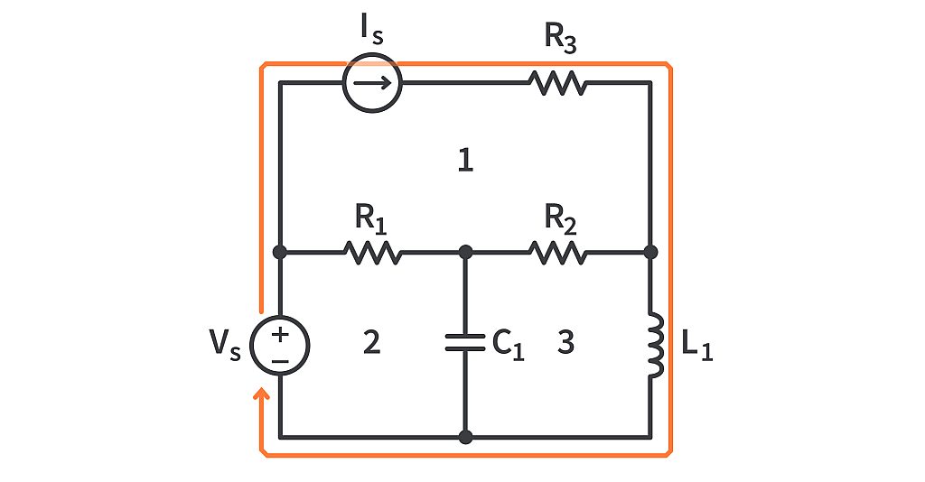
Example 3 (Supermeshes)

With KCL, if we had a voltage source that wasn’t connected directly to reference ground, we would create a supernode and then, as part of the process, we would need to do a bit of KVL to finish the analysis. With KVL, if we have a current source that is shared between two meshes, we need to treat it in a similar way. We get rid of the current source and anything that is connected in series with it. We then treat the remainder as a single, larger supermesh.

Once we make that mesh, we create the equation to describe it. In this case, we get:

or

Now we have the equation for the supermesh but we have two unknowns and only one equation. So let’s put the current source back in with any elements that were in series with it and do KCL at the node where they connect to the bigger circuit. Once it’s in place, we use KCL at that node to create a second equation.

or

Now we have two equations and two unknowns! Let’s put this in the format needed to do some linear algebra and see what we get.

Becomes

And

Becomes

So our two equations are:
Which we put into a linear equation solver to get:


As I’m prone to making math errors, I prefer the linear equation method as it is usually faster and less likely that I screw up it. With the supermesh, this isn’t a common concern as, unless you’re dealing with transistors or CMOS level circuit design, current sources aren’t very typical. However, it’s a good tool to have in your toolbag in case it crops up and helps us better understand the relationship between the physical circuits and the mathematical representations.
Summary
That is our brief overview of Kirchhoff’s Voltage Law and how that leads to mesh analysis. You’ll note that we sometimes used mesh analysis and KVL interchangeably. While technically not the same, it is very common to hear them used like that. Depending on where you are and who you’ve studied with, you may find some other differences in approach, naming conventions, and even direction assumptions. However, despite these superficial differences, all mesh analysis comes down to finding the voltage across the different elements in a mesh. As long as you’re consistent and have a good understanding of what you’re doing, you should be able to get the answer you’re looking for.

Authored By
Josh Bishop
Interested in embedded systems, hiking, cooking, and reading, Josh got his bachelor's degree in Electrical Engineering from Boise State University. After a few years as a CEC Officer (Seabee) in the US Navy, Josh separated and eventually started working on CircuitBread with a bunch of awesome people. Josh currently lives in southern Idaho with his wife and four kids.

Related Tutorials

Explore CircuitBread
- 244 Tutorials
- 9 Textbooks
- 12 Study Guides
- 31 Tools
- 104 EE FAQs
- 295 Equations Library
- 213 Reference Materials
- 97 Glossary of Terms
Friends of CircuitBread
-

Search Hundreds of Component Distributors + 2 Perks
-

Relays, Switches & Connectors Knowledge Series
-

Free eBook & Resource Library + 1 Perk


Get the latest tools and tutorials, fresh from the toaster.


