If you’re working in a schematic program, and need to test your circuit IRL, you’ll likely be transferring your design to a breadboard. Setting up a circuit on a breadboard can be a piece of cake or a messy nightmare of wires and endless troubleshooting. How you approach populating your breadboard from the start can make all the difference.
Here are some tips on getting a circuit you’ve designed onto a breadboard and working:
1) Leg length
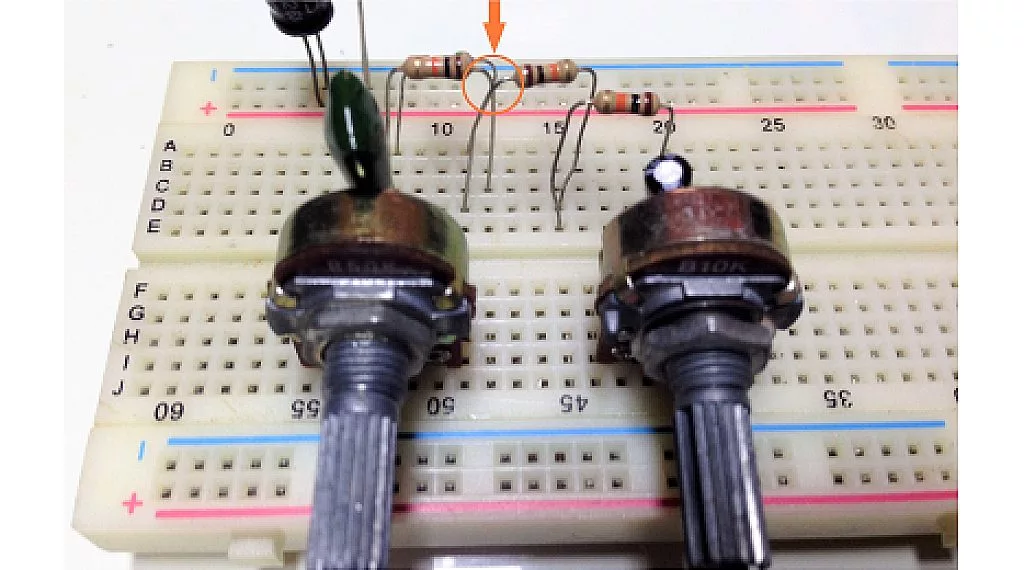
Be careful about wires and component legs touching where they shouldn’t. With long leads, some of your components can touch each other unintentionally. Depending on how permanent your breadboard layout is and the cost of the components, you could consider trimming the leads to the appropriate length. But if you do that and then move parts around and they no longer reach, that is an unfortunate frustration.
2) Symbols

Your circuit will have a BOM (bill of materials) that is very specific as far as values and types of components required to make the circuit function. If you order a set of parts specifically to build the circuit there shouldn’t be much trouble selecting the right parts. If you’re in a class setting or have a large box of parts to choose from though, you’ll need to understand the schematic symbols so that you place the correct type of component and in the right orientation in the circuit. Some symbols like caps, resistors, and diodes for example can have subtle differences between types and direction that you’ll need to notice.
3) Part verification

Things like resistors, capacitors, and inductors are especially easy to mix up values. Knowing the markings on them is a good way to avoid using the wrong values in your circuit and causing havoc. Axial resistors have color coding that you forget soon after learning, but it is easy to look up. Caps and inductors typically have number codes on them, but with limited space, they can be a shortened form that you’ll want to understand before placing on the board. To make sure the values are correct and within the specified value, a DMM (digital multimeter) or LCR (inductance, capacitance, resistance meter - much less common and more expensive than a DMM) is a very handy tool to have.
4) Jumpers

Jumpers are a handy way to quickly make a connection on a breadboard. They often can help with visualizing your circuit because they come in many colors. A downside to jumper wires is that they are usually too long and end up looping and covering up your board to the point of making it difficult to see what connection you’ve made or need to troubleshoot. An alternative to long flexible jumper wires are pre-cut, stripped, and bent solid wire jumpers that that can make low profile connections. By selecting them carefully for length and color, very neat breadboard layouts are possible. These also feature many colors and lengths, but are less flexible in terms of grabbing one and making a quick connection between two points.
5) Troubleshooting on breadboards
Plugging into the wrong holes creating connection between things that shouldn’t be connected or not connecting things that should is very common. This seems to be most frequently done with power and ground. Color coding and taking your time will help with this.

Sometimes components or wires are not fully seated in the terminal to make contact, and they can be tough to figure out. While difficult to see, if you pay attention, you can tell if the jumper wire or resistor lead or whatever is actually going in. If you only press it up to the internal contact but don’t get it in, it either won’t work, or worse, will work intermittently, which is incredibly frustrating to debug.

Another problem that leads to trouble is messy breadboards with long, out-of-control jumpers, criss-crossing wires and random placement of components. Messy breadboards with wires all over the place are hard to follow and troubleshoot. Take a breath, take your time, and try and make your breadboard more organized and prettier. And, if possible, color code things.
Hopefully these tips will help you get your circuit moved from a design on a schematic to a breadboard smoothly. The biggest things are to just take your time and follow the connections on the schematic. Concentrate on one connection or component at a time to make sure each connection in the schematic is made. It won’t take long to get everything placed on the board, so again, taking time to make sure each connection is made with the correct components will give your breadboard circuit a high chance of working from the start. Even then, mistakes in circuit design and mistakes in breadboard layout happen often, so a good layout that you can systematically troubleshoot should see you to the finish.

