A circuit breaker is an electrical switch employed in electric circuits to connect and disconnect the load when required. Besides manual connection and disconnection of the load, circuit breakers have one more important role in a circuit - to protect the circuit components from overcurrent in case of a fault or overload. Under such abnormal conditions, the current in the circuit increases rapidly and circuit breaker contacts open, interrupting the path of current flow and thus breaking the circuit.
The majority of industrial loads are inductive in nature. The problem with conventional circuit breakers is that for the high current to be interrupted, the contacts of the circuit breaker must physically move apart from each other. If the load is inductive, a large voltage spike (due to L*di/dt) appears across the contacts of a circuit breaker when they try to move and an arc is generated between the contacts in the process. Auxiliary arrangements are needed to extinguish the arc and the service life of the circuit breaker is limited by the erosion of contacts due to their exposure to the high temperature of the arc.
All the functions performed by a circuit breaker can be handled with power semiconductor devices, using them as controlled switches. Since they have no moving parts, power semiconductor devices are known as static switches. And when they are implemented as a circuit breaker, they are called static circuit breakers.
Static Circuit Breakers
Controllable power semiconductor devices like a thyristor start conducting current when it is forward biased, and its gate is energized. It continues to conduct current while the voltage across it is positive and stops conducting current as soon as the voltage across it becomes negative.
The circuit in the image below shows how two thyristors are connected in an inverse parallel configuration. The circuit is fed from a transformer which connects to the distribution system. Gate triggering pulses to the thyristors are provided by the gate control circuit via the pulse triggering transformers. This is required to isolate the high power thyristor circuit from the low power gate control circuit.
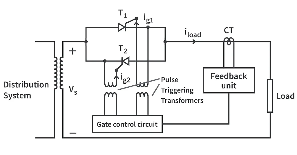
The load current is measured with the help of a current transformer and the same is constantly fed back to the gate control circuit which constantly monitors the load current and plans the triggering pulses in accordance.
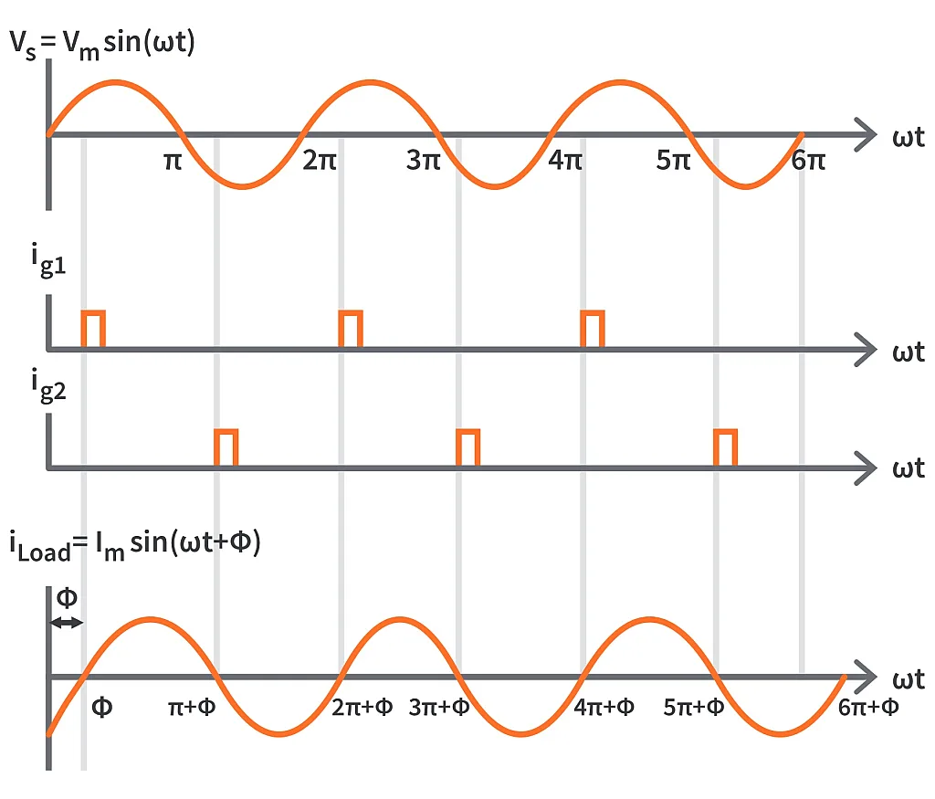
The gate pulses are synchronized with the 0 crossing of the load current. Since the load is inductive in nature, the current lags the voltage by the power factor angle Ф. In the positive half cycle of the load current, T1 is fired and T2 is reverse biased. T1 conducts load current from Ф to π+Ф.
In the negative half cycle of the load current, T2 is triggered and T1 is reverse biased. Hence T2 conducts the load current in this duration. Such synchronized operation of the two thyristors ensures uninterrupted flow of current to the load as shown in the timing diagram below.
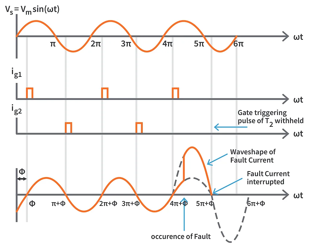
Suppose a fault occurs, and the magnitude of current in the circuit exceeds the preselected level, the gate control circuit will withhold the gate pulse from then on. The thyristors won't be fired due to the unavailability of the gate pulse and hence won't conduct the current. This way the fault current is interrupted successfully. The thyristors should be chosen carefully for such designs because they must be able to block the high voltage which appears across them on the occurrence of a fault.
Say the fault occurs at instant say anywhere between 4π+Ф to 5π+Ф. The load current will be broken only at 5π+Ф when T1 stops conducting and the gate triggering pulse of T2 is withheld. This shows that the maximum possible delay for breaking the circuit is one half cycle that is π/ω seconds.
The gate pulse control circuit may need resetting once the fault has been cleared to resume the normal operation.
In a conventional circuit breaker, the minimum time required for interruption of fault current is about 2-3 half cycles depending on the magnitude of the fault current. One of the main advantages that a static circuit breaker has over a conventional circuit breaker is that it has faster operation. The design specifications of controllable power semiconductor switches for such applications include high voltage rating and high inrush current withstanding capability.
However, the usage of such high quality power semiconductor switches as static circuit breakers is not justified for applications where the load is highly resistive like in household lighting/heating loads. Keeping in mind that every circuit needs a separate circuit breaker and high rating power semiconductor devices are more costly, it's just not economical to arrange for a static circuit breaker for every circuit in each house. This is a large part of why static circuit breakers aren't employed in residential loads. On the other hand, arcing and its detrimental effects are more serious in inductive loads which constitute the majority of industrial loads. Static circuit breakers are best suited in industrial applications where engineers are looking for long-term, maintenance-free solutions.


