Semiconductor diodes are widely used components in many electronic circuit designs. Different diode types are optimized to provide different characteristics exploited in circuit designs. An important function of diodes is for rectification.
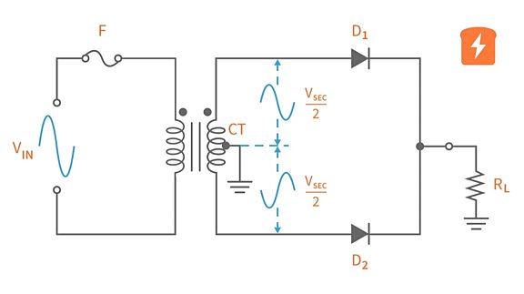
Half wave rectifier circuits are used for power rectification, signal demodulation and peak detection while two-diode circuits provide full wave rectification when used with a center-tapped transformer. Today, the two-diode rectifier circuit is not as commonly seen as four-diode bridge rectifiers that can be constructed with or without a transformer which greatly reduces cost for the circuit.


With that, three diode considerations for rectifier circuits are as follows:
1) Turn on Voltage
The typical turn on, or forward voltage of a silicon diode is 0.7V while that of a germanium diode is around 0.2-0.3V. Reducing the forward voltage drop increases the diode rectifier sensitivity which is relevant in certain applications such as signal detection.
2) Diode Current Rating
The amount of load current that flows through a diode determines the desired continuous current rating. For example, if the load draws 1A of current then a 1N1007 diode (rated 1A) will suffice (though without a safety margin!) However, if the load current is more than 1A, then a diode with a higher current rating is required. The load current must not exceed the continuous current diode rating. The same can be considered for the supply current. If the design requires a 3A power supply, the diode should be able to handle 3A of current. The supply current should never exceed the diode current rating, even if only momentarily.
3) Peak Inverse Voltage
The diodes must withstand the peak inverse voltage across them. When a capacitor smooths the output, the voltage value is the peak of the input waveform, which is √2 times the RMS voltage.

On the other half of the wave cycle, the peak voltage value is another √2 times the RMS voltage. The sum of the two values is the maximum inverse voltage across the diode. Thus the PIV diode rating should be at least 2 x √2 times the input RMS voltage for half wave rectifier circuits and at least four times the peak transformer voltage for two-diode full wave rectifier circuits, accounting for possible transients.

In bridge rectifiers, diodes with half the PIV rating of those in a center-tapped rectifier are required for the same output voltage.

Considering these three important specifications will ensure that a diode will function as a rectifier without damaging them or the rest of the project that this is in.


