Transformers - Principle of Operation
A transformer is a device that connects two electrical circuits through a shared magnetic field. Transformers are used in impedance transformation, voltage level conversion, circuit isolation, conversion between single-ended and differential signal modes, and other applications.1 The underlying electromagnetic principle is Faraday’s Law (Section 8.3) – in particular, transformer emf.
The essential features of a transformer can be derived from the simple experiment shown in Figures 8.5.1 and 8.5.2. In this experiment, two coils are arranged along a common axis. The winding pitch is small, so that all magnetic field lines pass through the length of the coil, and no lines pass between the windings. To further contain the magnetic field, we assume both coils are wound on the same core, consisting of some material exhibiting high permeability. The upper coil has

turns and the lower coil has

turns.
In Part I of this experiment (Figure 8.5.1), the upper coil is connected to a sinusoidally-varying voltage source

in which the subscript refers to the coil and the superscript refers to “Part I” of this experiment. The voltage source creates a current in the coil, which in turn creates a time-varying magnetic field

in the core.
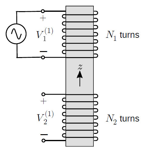
Figure 8.5.1: Part I of an experiment demonstrating the linking of electric circuits using a transformer.
The lower coil has
turns wound in the opposite direction and is open-circuited. Given the closely-spaced windings and use of a high-permeability core, we assume that the magnetic field within the lower coil is equal to
generated in the upper coil. The potential induced in the lower coil is

with reference polarity indicated in the figure. From Faraday’s Law we have

where

is the flux through a single turn of the lower coil. Thus:

Note that the direction of

is determined by the polarity we have chosen for

.
In Part II of the experiment (Figure 8.5.2), we make changes as follows. We apply a voltage

to the lower coil and open-circuit the upper coil. Further, we adjust
such that the induced magnetic flux density is again

– that is, equal to the field in Part I of the experiment.
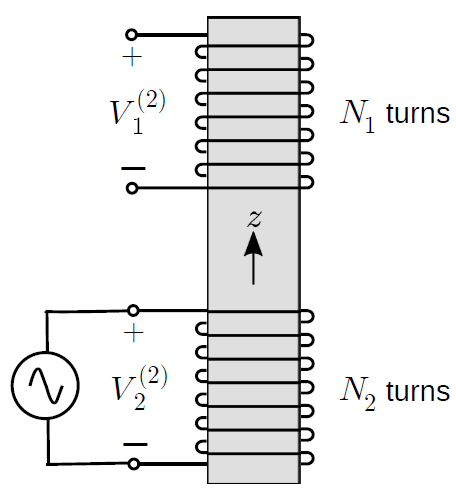
Figure 8.5.2: Part II of an experiment demonstrating thelinking of electric circuits using a transformer
Now we have

which is

For reasons that will become apparent in a moment, let’s shift the leading minus sign into the integral. We then have

Comparing this to Equations 8.5.1 and 8.5.2, we see that we may rewrite this in terms of the flux in the lower coil in Part I of the experiment:

In fact, we can express this in terms of the potential in Part I of the experiment:

We have found that the potential in the upper coil in Part II is related in a simple way to the potential in the lower coil in Part I of the experiment. If we had done Part II first, we would have obtained the same result but with the superscripts swapped. Therefore, it must be generally true – regardless of the arrangement of terminations – that

This expression should be familiar from elementary circuit theory – except possibly for the minus sign. The minus sign is a consequence of the fact that the coils are wound in opposite directions. We can make the above expression a little more general as follows:

where

is defined to

when the coils are wound in the same direction and

when coils are wound in opposite directions. (It is an excellent exercise to confirm that this is true by repeating the above analysis with winding direction changed for either the upper or lower coil, for which
will then turn out to be
.) This is the “transformer law” of basic electric circuit theory, from which all other characteristics of transformers as two-port circuit devices can be obtained (See Section 8.6 for follow-up on that).
Summarizing:
The ratio of coil voltages in an ideal transformer is equal to the ratio of turns with sign determined by the relative directions of the windings, per Equation 8.5.9.
A more familiar transformer design is shown in Figure 8.5.3 – coils wound on a toroidal core as opposed to a cylindrical core. Why do this? This arrangement confines the magnetic field linking the two coils to the core, as opposed to allowing field lines to extend beyond the device. This confinement is important in order to prevent fields originating outside the transformer from interfering with the magnetic field linking the coils, which would lead to electromagnetic interference (EMI) and electromagnetic compatibility (EMC) problems. The principle of operation is in all other respects the same.
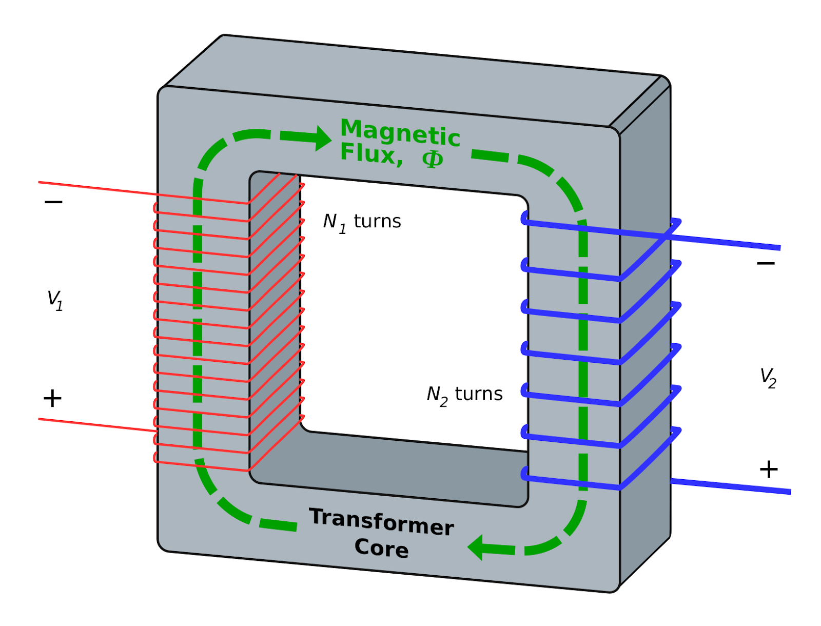
Figure 8.5.3: Transformer implemented as coils sharing a toroidal core. Here

. Image used with permission (CC BY SA 3.0; BillC).
Footnotes
- 1
See “Additional Reading” at the end of this section for more onthese applications.
Additional Reading
- “Transformer” on Wikipedia.
- “Balun” on Wikipedia.
Ellingson, Steven W. (2018) Electromagnetics, Vol. 1. Blacksburg, VA: VT Publishing. https://doi.org/10.21061/electromagnetics-vol-1 CC BY-SA 4.0
Explore CircuitBread


Get the latest tools and tutorials, fresh from the toaster.


