Introduction to Systems
Signals are manipulated by systems. Mathematically, we represent what a system does by the notation

, with

representing the input signal and

the output signal.
Definition of a system
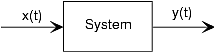
Figure 1. The system depicted has input

and output

. Mathematically, systems operate on function(s) to produce other function(s). In many ways, systems are like functions, rules that yield a value for the dependent variable (our output signal) for each value of its independent variable (its input signal). The notation

corresponds to this block diagram. We term

the input-output relation for the system.
This notation mimics the mathematical symbology of a function: A system's input is analogous to an independent variable and its output the dependent variable. For the mathematically inclined, a system is a functional: a function of a function (signals are functions).
Simple systems can be connected together--one system's output becomes another's input--to accomplish some overall design. Interconnection topologies can be quite complicated, but usually consist of weaves of three basic interconnection forms.
Cascade Interconnection
cascade
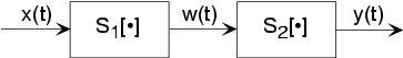
The simplest form is when one system's output is connected only to another's input. Mathematically,

, and

, with the information contained in

processed by the first, then the second system. In some cases, the ordering of the systems matter, in others it does not. For example, in the fundamental model of communication the ordering most certainly matters.
Parallel Interconnection
parallel

A signal
is routed to two (or more) systems, with this signal appearing as the input to all systems simultaneously and with equal strength. Block diagrams have the convention that signals going to more than one system are not split into pieces along the way. Two or more systems operate on
and their outputs are added together to create the output

. Thus,

, and the information in
is processed separately by both systems.
Feedback Interconnection
feedback

The subtlest interconnection configuration has a system's output also contributing to its input. Engineers would say the output is "fed back" to the input through system 2, hence the terminology. The mathematical statement of the feedback interconnection is that the feed-forward system produces the output:

. The input

equals the input signal minus the output of some other system's output to
:

. Feedback systems are omnipresent in control problems, with the error signal used to adjust the output to achieve some condition defined by the input (controlling) signal. For example, in a car's cruise control system,
is a constant representing what speed you want, and
is the car's speed as measured by a speedometer. In this application, system 2 is the identity system (output equals input).
This textbook is open source. Download for free at http://cnx.org/contents/778e36af-4c21-4ef7-9c02-dae860eb7d14@9.72.
Explore CircuitBread


Get the latest tools and tutorials, fresh from the toaster.


