Ohm's Law, Power Sources, Branches, Nodes & Loops | Components of an Electrical Circuit
Published
Introduction
In our exploration of the world of electric circuits, we start with building the essential foundations of circuits - learning the fundamental terms and concepts related to electricity, paving the way to comprehend the underlying principles governing circuits. Working with our Friend of CircuitBread, Digilent, our initial steps involved grasping the fundamental concepts that define voltage, current, and resistance, laying the groundwork for a deeper understanding.
If you missed our introductory blog covering the basics of circuits, I highly recommend checking it out here: Voltage, Current, and Resistance - Introduction to Circuit Analysis. Building upon our foundational knowledge so far, let's shift our focus toward understanding the structure of circuits, starting with the different components that make up a circuit.
Types of Circuit Elements
Circuit elements can be divided into two types: active and passive elements. While learning the fundamentals of voltage and current, we typically begin with passive elements for simplicity.
A passive element in a circuit is one that either stores or dissipates energy. Active circuit elements, on the other hand, can supply power to a circuit from an external source. Some examples include batteries and generators. In other words, they provide that push to move charges across a circuit. However, beyond these, there exist other active components, often non-linear in nature, that significantly impact circuit behavior. Components like transistors, diodes, and other non-linear active elements play a crucial role by controlling or modulating the flow of electricity, enabling advanced functionalities within circuits. They contribute significantly to signal amplification, regulation, or even signal processing in complex electronic systems.
In this tutorial, we will be discussing two essential active circuit components: voltage and current sources. These sources are classified as either dependent or independent.
Independent sources, like batteries and generators, provide a set voltage or current regardless of the circuit's condition. These sources don't alter their output based on the surrounding circuit's behavior, making them essential elements for powering various electrical systems.
On the other hand, dependent sources generate voltage or current based on another voltage or current in the circuit. Dependent sources are outside the scope of discussion for this tutorial, but if you are interested in learning more about them, please check out our blog on Voltage and Current Sources, which features a section about dependent sources.
Independent Voltage Sources
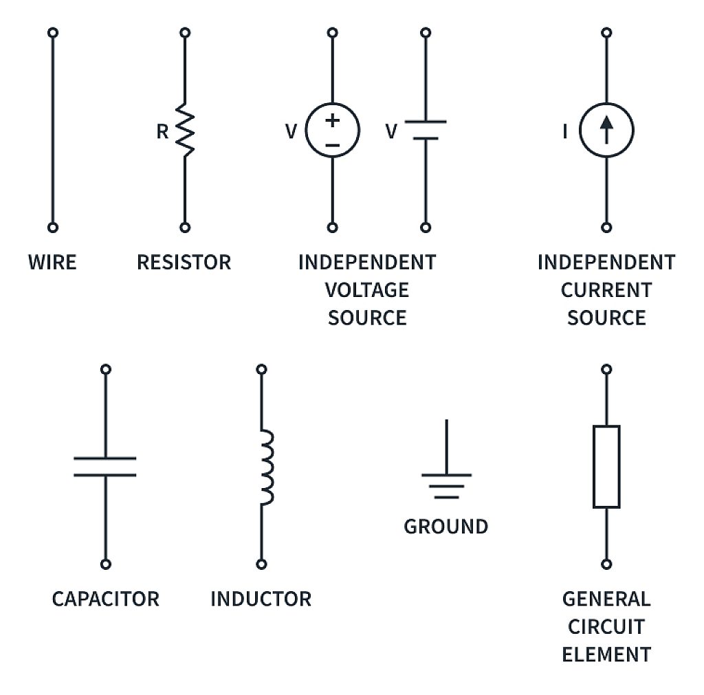
Independent voltage sources are circuit elements that maintain a specified voltage across their terminals. They can provide either a constant voltage or a time-varying one. You may be familiar with the symbol used to depict constant voltage sources.

In electrical circuits, time-varying voltage sources are usually represented by a circle symbol with a sine wave inside. This symbol denotes an alternating voltage source, typically producing a sinusoidal waveform.

However, in most cases, we use the symbol given below to represent all independent voltage sources.

The symbols for voltage sources indicate the direction or polarity of the voltage being supplied, eliminating the need to make assumptions about the polarity of these sources.
However, the direction of current flow is not specified on the symbol and must be determined through circuit analysis or assumed according to the rules of passive sign convention.
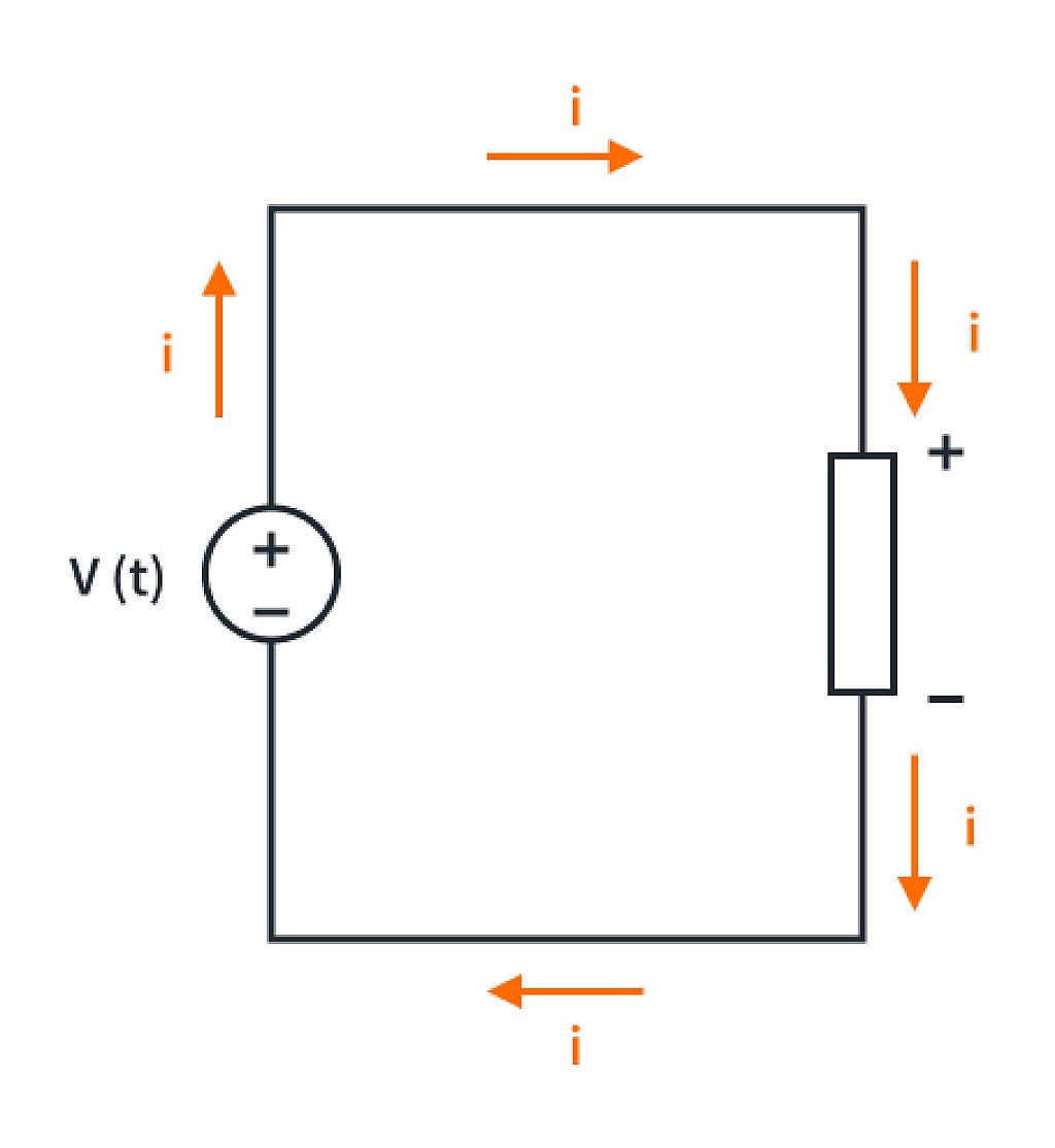
According to passive sign convention, current flows from the positive terminal to the negative. Hence in the above circuit, direction of current flow can be assumed to be clockwise from the positive to negative terminal of the voltage source.
Independent Current Sources
An independent current source maintains a specific current regardless of voltage differences across its terminals. The symbol used to represent such a source is shown below, and it can deliver either time-varying or constant current.

Similar to voltage sources, the symbols for current sources indicate the sign of the current being supplied, removing the need to assume a direction for the current. However, the polarity of voltage across the terminals isn't specified and needs to be determined through circuit analysis or assumed according to the passive sign convention.

According to passive sign convention, current enters a circuit element at the positive terminal. Hence in the above circuit, voltage polarity across the circuit element can be assumed based on the current direction.
To summarize, there are two primary types of circuit elements: active and passive. Active elements like batteries supply electric energy to the circuit, whereas passive elements like resistors store or dissipate this energy.
Our focus so far has been on active circuit elements, specifically independent sources like voltage and current sources. The next section will cover resistors, a significant passive element, while also exploring the relationship between voltage/current sources and resistance.
Resistance
In our previous discussions, we have introduced the concept of resistance in electric circuits. Resistance, measured in ohms (Ω), hinders the flow of electric current in a circuit, causing it to slow down.
One important thing to note is that resistance is an inherent property found in nearly all materials, representing the energy loss incurred when an electrical current passes through a conductive element. When electric charges move through a circuit element, energy is dissipated in the form of heat. Resistors are passive circuit elements that exhibit these energy loss characteristics and are represented by the following symbol.

Resistors are often used in circuit diagrams to symbolize and represent the resistance encountered in real-world electrical components. They serve as models to represent the opposition to the flow of electrical current within a circuit.
This representation allows us to analyze and design circuits by showing how resistance affects current and voltage flow. By using resistors in circuit diagrams, it becomes easier to predict how the circuit will behave based on the resistance encountered at different points.
Ohm’s Law
Ohm’s law is a simple yet fundamental law that describes the relationship between voltage, current, and resistance.
Ohm's Law states that the voltage (v) across a conductor or resistor is directly proportional to the current (i) passing through it, given a constant resistance (R).
Mathematically, it is expressed as
where v(t) is the voltage across the conductor or resistor (in volts), i(t) is the current flowing through the conductor or resistor (in amperes), and R is the resistance of the conductor or resistor (in ohms).
Expressing voltage and current as a function of time accommodates scenarios where these electrical quantities can fluctuate over time due to changes in the circuit or external factors.
When starting with circuit analysis, we often focus on the DC aspect, simplifying the analysis by considering constant or average values of voltage and current rather than their time-varying aspects. This simplification aids in easier analysis and understanding of circuit behavior and is still applicable in real-world circuits where constant voltages and currents are predominant, such as with batteries or power supplies.
It is important to note that resistors always dissipate energy, and the value of resistance always has to be positive. As you may observe in the figure below, current enters the resistor from the terminal with the highest voltage potential, obeying the passive sign convention and ensuring a positive resistance value. This also indicates that resistors always absorb power.

Interestingly, negative resistance is an uncommon yet fascinating electrical property seen in certain components where increasing voltage causes a subsequent decrease in current. It is only observed in specialized materials or components and is not typical in most everyday circuits.
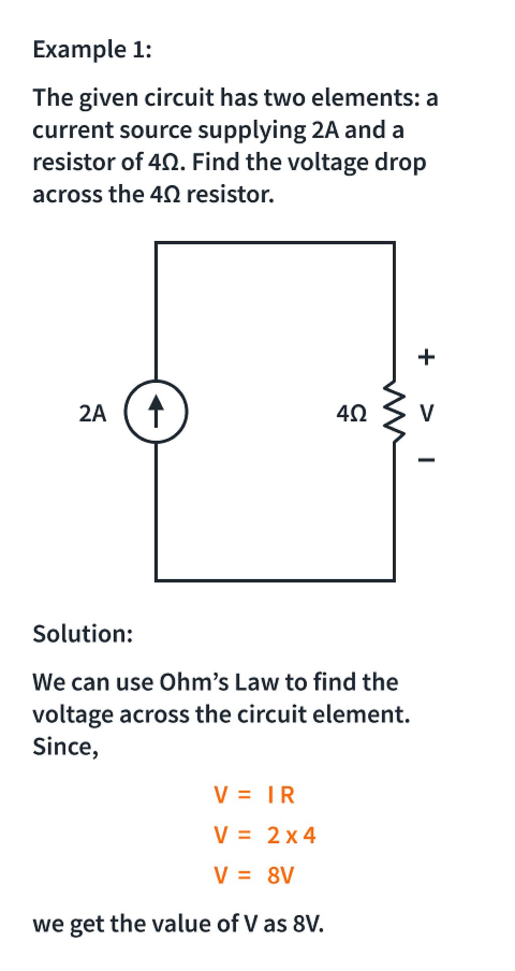
Now that we've gained insight into various types of active and circuit elements, let's examine Ohm's Law with a few examples.

Branches, Nodes and Loops
Up until now, our focus has been on basic circuits featuring only one circuit element alongside either a voltage or current source. However, the complexity of problems will ramp up quickly as we progress further into the series, as we’ll be dealing with circuits having multiple sources and elements. This is where Digilent’s powerful circuit analysis tools like Analog Discovery 3 will come handy to us. In the meantime, it's crucial to understand the specific terms used to describe the comparatively more complex circuit structures. There are three important terms used to describe a circuit: branches, loops, and nodes.
A branch is any component in a circuit that possesses two terminals. These include common circuit elements like resistors, capacitors, and inductors, as well as voltage/current sources.
Stepping back from individual components to view a broader perspective of a typical circuit, let's look into the junctions where these branches connect — referred to as nodes.
Nodes or junctions form in circuits when components connect to each other or when multiple wires converge. It's a junction that doesn't impede the flow of current. Essentially, nodes represent connection points in the circuit.
In the below circuit, there are four nodes: Node A links resistor 1 and resistor 2, node B connects resistor 2 and resistor 3, node C joins the voltage source and resistor 3, while node D connects resistor 1 and the voltage source.

It is important to note that any points in a circuit which are connected by perfect conductors will be at the same voltage and will thus be part of the same node.
To understand this better, let's look at another example of a circuit with four nodes.
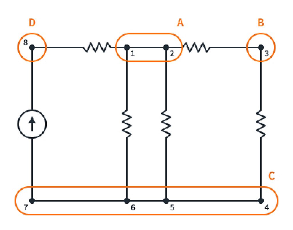
As you may observe, the circuit appears to have eight meeting points or junctions, suggesting the presence of 8 nodes. However, points 1 and 2 have no circuit elements between them, making them electrically identical and therefore considered as one node. Similarly, points 4, 5, 6, and 7, linked by perfect conductors with no circuit elements in between, share the same voltage potential and are considered as one node.
Short circuits happen when two nodes in a circuit, expected to be at different voltages, accidentally connect. When two nodes at different voltages connect, the resistance (R) between them decreases significantly, potentially approaching zero. This sudden drop in resistance occurs because of the direct connection, creating a low-resistance path.
According to Ohm's Law, when resistance approaches zero, the equation V=I×R suggests that for any finite voltage (V), the resulting current (I) increases significantly. Hence in a short circuit, where the resistance approaches zero, the consequence is an enormous spike in current flow through the circuit.
This sudden surge can cause overheating, component damage, and circuit malfunctions, posing safety risks.
Another important term to understand in circuit structures is loops. Nodes represent the junctions where elements connect, while loops outline the closed pathways formed by these connected nodes.
A loop is a closed path within a circuit that starts and ends at the same node, encompassing various elements such as resistors, sources, and wires. When analyzing a circuit, choosing specific loops helps simplify the analysis.
In our previous example of a circuit with 4 nodes, there are various possible ways to loop through the circuit as seen below.
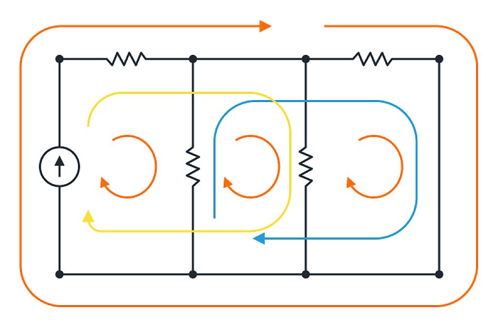
For beginners, choosing loops in a circuit can begin with identifying simple closed pathways formed by components. Start small, focusing on key elements like resistors or voltage sources. Practice recognizing single-element loops, avoiding overlaps, and gradually advancing by practicing loop identification in various circuits to build confidence and circuit analysis skills.
Series and Parallel Circuits
In circuits, components can be arranged in series or parallel configurations, impacting how current flows and how nodes and loops form.
Series Configuration: Components in series connect one after the other, creating a single pathway for current. This connection involves components sharing a common node, where they're linked end-to-end, with no other components branching off from that shared point. Each element shares the same current, and the total resistance is the sum of individual resistances. In a series arrangement, nodes are where components connect end-to-end, and there is only one loop that covers the entire circuit.

Parallel Configuration: Parallel components create multiple pathways for current flow. Each element shares the same voltage, and the total resistance is calculated differently than in series (using the reciprocal formula). Nodes in parallel setups are where multiple branches converge, and there are multiple loops due to the different current paths.

However, many circuits combine both series and parallel configurations of components. Such hybrid arrangements create complex pathways for current flow. In these circuits, understanding and identifying nodes and loops becomes essential for analysis.
Conclusion/Summary
As we conclude our exploration of circuit structures, we've taken a significant step toward solving real-world circuit problems and delving into practical examples.
Having understood voltage, current, resistance, and the functions of active and passive elements, we've explored fundamental concepts governing circuit behavior. Examining nodes, loops, and branches in circuits sheds light on how electrical components are interconnected, affecting the flow of current.
Understanding series and parallel circuits strengthens our grasp of circuit structures, revealing the different paths for current. Our understanding of Ohm's Law, the importance of resistors, and the roles of voltage and current sources lays the groundwork for detailed circuit analysis.
This tutorial was developed in collaboration with Digilent, whose partnership and support have been indispensable. They have always been proactive in promoting academic development among students, a commitment also reflected in the academic discounts they offer. We extend our sincere appreciation for their valuable contribution to the student community.
We will be using the concepts we’ve learned in this tutorial to explore a few more circuit laws in the next tutorial!
Check Yourself
23 Questions

Get the latest tools and tutorials, fresh from the toaster.


