Why can't I share a resistor on the common anode or cathode of my RGB LED?
Published
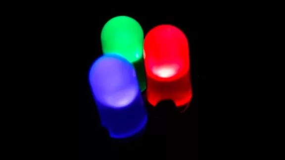
In our discussion about how an RGB LED works, we’ve mentioned that an RGB LED is basically an LED package with three internal LEDs (red, green, and blue) inside it. In order to get the color that we want from an RGB LED, we need to forward bias and control the intensity of each internal LED.

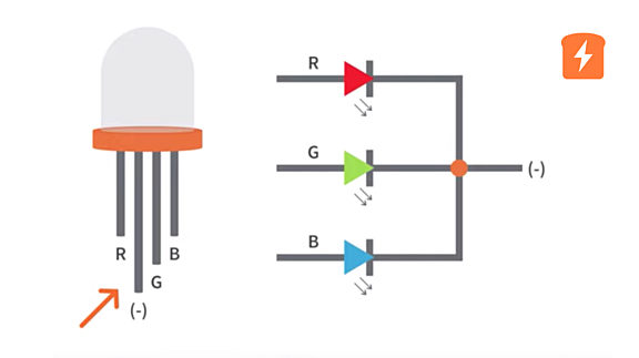
In an RGB LED package, the LEDs inside almost always share either a common anode or cathode. This makes people think that they can just use a single resistor to limit the current for all the three LEDs as shown in the circuit diagram below. When you just want just one of the LEDs to emit light, of course, it will work. However, when you try to get the color that you want, you will have a hard time when you will just use a single resistor.

For example, I have a common cathode RGB LED and just use a single resistor for the red, green, and blue LEDs. When I turn on the LEDs individually, everything’s good. But when I turn on the red and the blue LEDs to mix their colors, it doesn't make that much of a difference. And if I try to fully turn on the red, green, and blue LEDs expecting that I would get a fairly pure white light, I get a very red tinge.

So, what's going on? The problem here is the forward voltage of the LEDs. In our “How to dim an LED tutorial”, we’ve discussed that the luminous intensity of an LED depends on the forward current. However, the forward current of an LED also depends on the forward voltage or the voltage drop across the LED. So if the voltage drop across the LED is not enough to have the required forward current, you won’t get the desired luminous intensity of the LED.
Now, let’s discuss what happens when we use a single resistor on an RGB LED. We can assume that our power source is 5V, then the typical forward voltage of the red LED is 2V, while the green and the blue LEDs would be around 4V. As indicated in the diagram, the LEDs are obviously connected in parallel, a crucial aspect to this problem. With ideal LEDs, only the red LED would be able to conduct here since it has the lowest forward voltage, then the voltage drop across the green and blue LEDs would be the same with the red LED, 2V. If you have 2V across an LED that has a 4V forward voltage, you're not going to actually have any current through it.

There will likely be a small amount of current flowing through the other LEDs because the green and blue LEDs will start to conduct a little bit less than their forward voltage and the actual voltage across the red LED will be a little bit more than the 2V forward voltage because you're going slightly past the rated forward voltage. Despite this, there's definitely going to be a huge imbalance between the current going through the different LEDs in the array.
With an LED array where all the LEDs are the same color, you’ll actually still run into this problem. The forward voltage will vary slightly from LED to LED even within the same array so that you will brightness differences. Honestly, though, this isn’t the biggest problem with sharing a resistor on a common cathode or anode within an array. While not the overriding problem with RGB LEDs, your single resistor has another issue.

When you have a single resistor and a single LED, you can calculate the maximum current that will go through that resistor. But with a single resistor and multiple LEDs, that resistor now needs to channel the current that flows through ALL of the LEDs. As the individual LEDs turn on and off, the only way to maintain a constant brightness output on each LED would be to vary the voltage across the resistor, which is typically not possible and never sensible. As the voltage across the resistor won’t change, that means the current remains constant, which means that the current is now split between multiple LEDs. If they’re all on, this makes them dimmer individually than if they were on only one at a time - and a well designed circuit won’t cause one light to be dimmer or brighter simply because you turned another light on or off.
And that is why you cannot share a resistor on a common anode or common cathode RGB LED or even on an LED array.
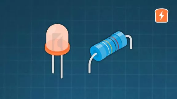
So you really need to have one specific resistor for each of the LEDs in an RGB LED or LED array. When you check the datasheet of the RGB LED, check the forward voltage of each color. For example this RGB LED - Kingbright WP154A4SUREQBFZGC:

You’ll see that the red has a 1.9V typical forward voltage, while the blue and the green has 3.3V. From that, you can calculate the resistance of the resistor that you’re going to use for each of the LEDs.
So I hope that explains why you can't just use a single resistor on a common anode or common cathode RGB LED. If you’ve found this tutorial interesting or helpful, give it a like and if you have any questions, leave it in the comments below. To be notified about new tutorials about technology and electronics, please sign up for our newsletter!

Get the latest tools and tutorials, fresh from the toaster.


