Zener Diode as Voltage Regulator - Conceptual Overview
Published
In our previous topics relating to diodes, we’ve discussed the operation of a Zener diode as well as its important specifications. We’ve learned that a Zener diode is a special-purpose diode which works as a normal diode when forward biased but also permits current to flow when reverse biased, if its Zener voltage is surpassed. When its Zener voltage is surpassed, it maintains a stable reference voltage across it. With this characteristic, Zener diodes are often used as a simple voltage regulator and we’ll go over the practical usage of Zener diodes in this way.
What is a Voltage Regulator?
A voltage regulator is a device or a circuit with the purpose of creating a specific voltage while minimizing output variations with respect to variations in input, temperature, and load requirements. The most common use of a regulator are in power supplies, but any circuit that incorporates regulatory technique to give a controlled output or function can be considered as a regulator. Simply put, a regulator “regulates” the voltage to provide a constant DC voltage across the load.
Zener Equivalent Circuit
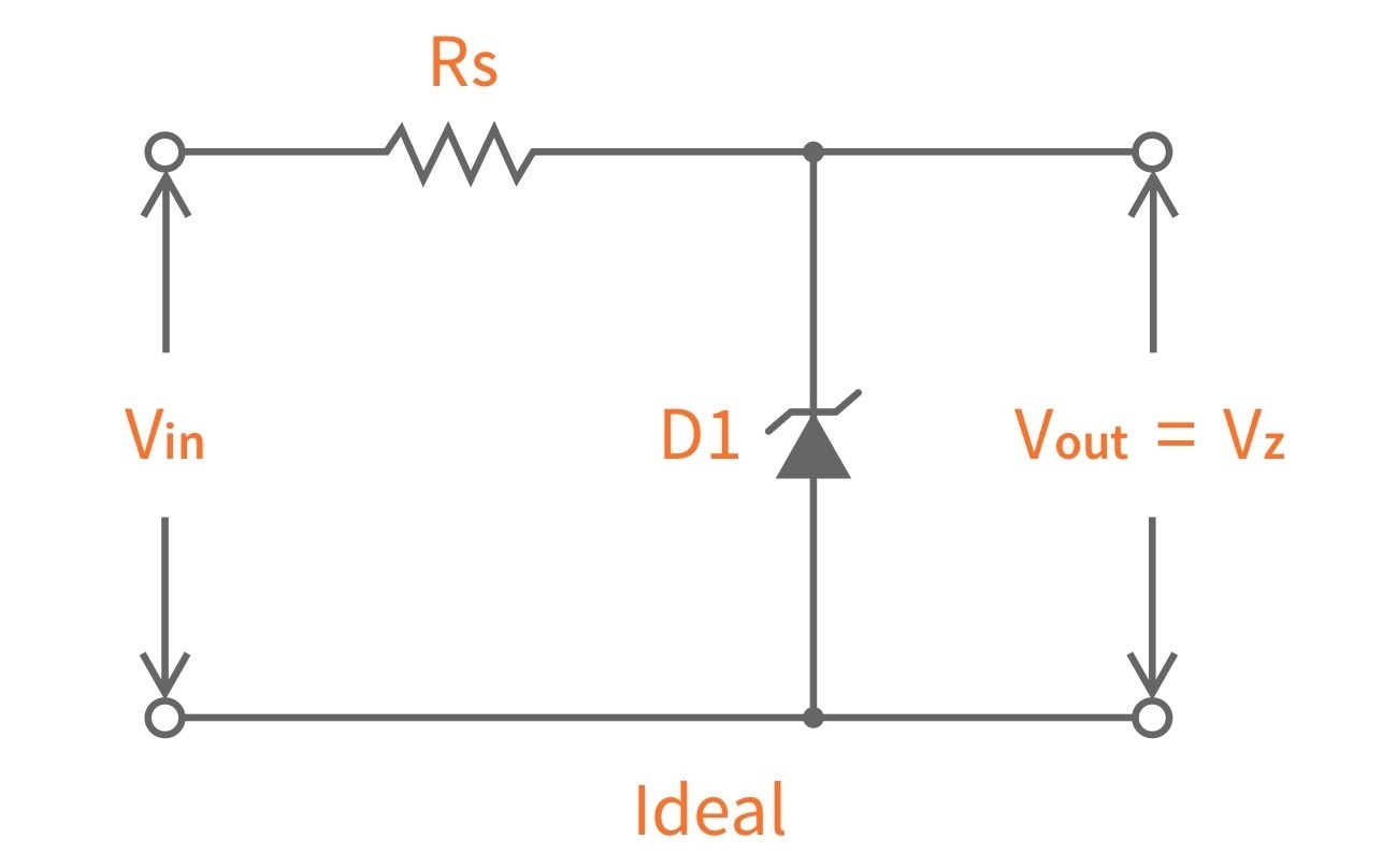
When a using Zener diode as a voltage regulator, ideally, it has a constant voltage drop equal to its nominal Zener voltage. This constant voltage drop across the Zener diode produced by reverse breakdown is represented by a DC voltage symbol (figure 1) even though the Zener diode does not produce a voltage. An ideal characteristic curve of the Zener diode is also shown below. (figure 2)


However, in reality, there exists a Zener impedance ZZ and the actual voltage curve is not perfectly vertical. There is a change in Zener current ΔIZ that produces a small change in Zener voltage ΔVZ. By Ohm’s law, the Zener impedance is equal to the ratio of ΔVZ to ΔIZ.

ZZ is usually specified at the Zener test current. Most of the time, ZZ is a small constant over a full range of Zener current values. However, if the Zener diode is operated near the knee of the curve, the Zener impedance changes drastically. Therefore, it's better to operate the Zener diode beyond the knee of the curve to get a more stable Zener impedance. Below is the practical model and characteristic curve of a Zener diode with its Zener impedance taken into account.


Using Zener Diode as a Voltage Regulator
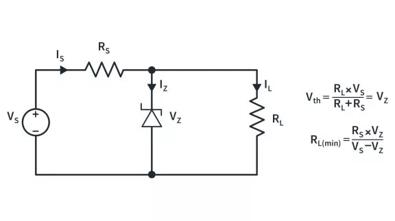
As mentioned, when a reverse bias that is equal or above the Zener voltage is applied to the Zener diode, the diode can maintain a stable voltage across it. With this characteristic, Zener diodes are used to regulate voltage in some circuits. The Zener diode voltage regulator is very economical as it is very inexpensive, simple and easy to build.
Before you build your own voltage regulator using Zener diodes, here are some important parameters to be considered. These parameters can be found in the datasheet, so it is very important to look at the datasheet of your Zener diode to ensure proper operation.

1. First, take note of the Zener diode’s rated breakdown voltage or Zener voltage. In the datasheet, it is denoted as VZ. This parameter specifies the amount of reverse-biased voltage that causes the diode to conduct current. For the diode to operate, the voltage applied across the Zener diode must be equal or greater than VZ.

2. Second, make sure that the minimum current IZK is exceeded. This is to keep the diode in breakdown for voltage regulation. It is not recommended to operate the Zener diode near the knee current because of the effect of Zener impedance.

3. Third, see to it that you do not exceed the maximum current IZM. Exceeding IZM may damage the Zener diode.
Zener Diode as a Voltage Regulator Drawbacks
Though Zener diodes are used as voltage regulators, they have a low efficiency for heavy load currents. It is because if the load current is large, there will be considerable power loss in the series limiting resistance (Rs). When the power dissipated on Rs exceeds its power rating, this will eventually damage the resistor. This is a common problem of a Zener diode voltage regulator.

Also, in reality the output voltage slightly varies due to Zener impedance as Vout = VZ + IZ ZZ. Changes in load current produce changes in Zener current. Consequently, the output voltage also changes. Therefore, the use of this circuit is limited to only such applications where variations in load current and input voltage are small.

In general, Zener diode regulators can provide a reasonably stable DC voltage at the output, but they are not particularly efficient. Its regulating ability is somewhat limited by the change in Zener voltage over a range of current values, which restricts the load current that it can handle. For this reason, they are limited to applications that require only low current to the load. To achieve better regulation and provide for greater variations in load current, the Zener diode is combined as a key element with other circuit components to create a 3-terminal linear voltage regulator.
Hopefully this theoretical yet practical overview of Zener Diodes as a Voltage Regulator is helpful and either gives you a good foundation for further usage of Zener diodes or clarifies some questions that you’ve had! If you have questions, please leave it in the comments below. See you in our next tutorial!

Get the latest tools and tutorials, fresh from the toaster.


