Hall effect sensors are magnetic sensors that output an electrical signal proportional to the intensity of the magnetic field around them. The electrical signal is then further processed by a special circuit to produce the required output. They are non-contact sensors, which means they do not have to come in contact with any physical element to generate an output because they are dependent on magnetic fields. This non-contact detection gives them a major advantage over other conventional types of physical contact sensors like limit switches. Before understanding the internal working of these sensors, we need to understand the Hall effect, the primary principle on which these sensors work.
The Hall Effect
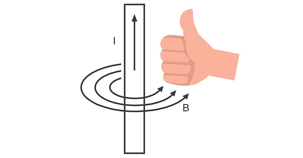
If you have a basic idea about magnetism and how it works, you’ll know that the flow of current through a wire generates a magnetic field around it. To get a better understanding, if you wrap your hand around a current-carrying wire such that your thumb points in the direction of current flow, the directions of the rest of your fingers will show the direction of the magnetic field. This is known as Oersted’s law.
Now that we know about this important concept of magnetism, we can move forward to understand what exactly is the Hall effect. Let’s take a conductive plate and apply a voltage across it. Just like any other conductor, a current will start to flow from one end of the battery to the other through the conductive plate. The charge carriers will flow in an almost straight line from one end of the plate to the other end, generating a current in the opposite direction as per conventional current flow. And as explained above by Oersted’s law, we know that this flow of current will induce a magnetic field around our conductive plate. The direction of the magnetic field generated here is shown using the arrows.
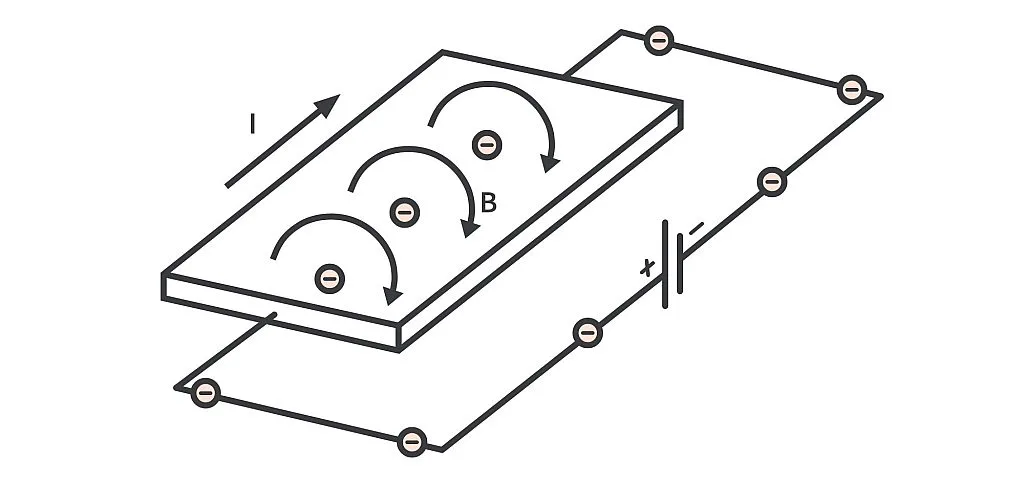
But what if I bring a magnet around that plate? This is the interesting part! This external magnetic field will interact with the existing magnetic field around the plate. This will cause a disturbance in the straight flow of charge carriers, deflecting the negatively charged electrons to one side of the plate and deflecting the positively charged holes to the other side of the conductive plate depending on the polarity of the external magnetic field. The force pushing the charge carriers towards the sides of the plate is generated due to the interaction of the two magnetic fields and is known as the Lorentz Force.
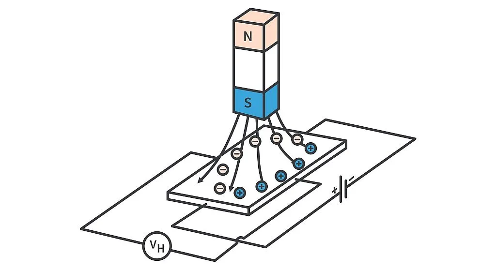
If we measure the voltage across the sides where the charge carriers got deflected, we’ll notice that there’s an extremely small potential difference present across it. The generation of this measurable voltage across the plate is known as the Hall Effect and is represented by VH in the above image.
Working of Hall Effect sensors
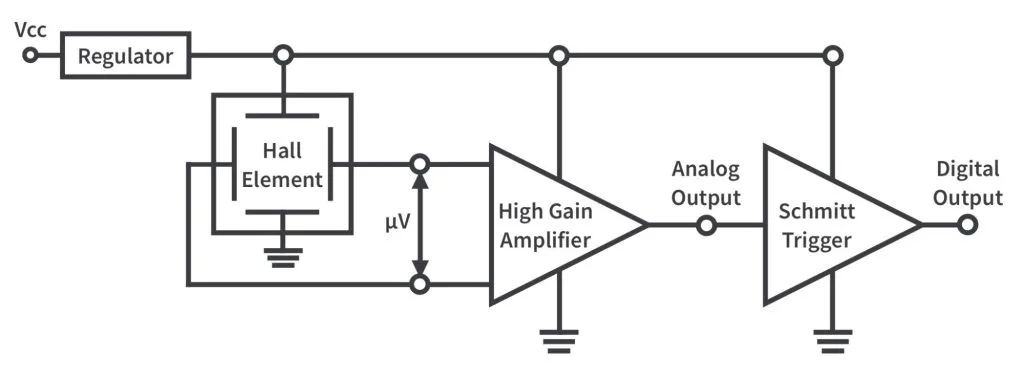
Figure 4 shows the basic components present inside a Hall effect sensor. First of all, there's a voltage regulator to bring the supply voltage to tolerable levels for the circuit. This regulated voltage is then applied across a thin rectangular p-type semiconductor plate, usually made up of gallium arsenide (GaAs), indium antimonide (InSb), or indium arsenide (InAs). This semiconductor plate is known as the Hall Element. Bringing an external magnetic field around the sensor generates a small potential difference across the other ends of the Hall element known as the Hall Voltage. This voltage is extremely small and hard to detect, usually in microvolts (µV), even if subjected to strong magnetic fields. To overcome this issue, the hall effect sensors consist of a high gain differential amplifier. The generated Hall voltage is then given as input to the amplifier which outputs an amplified voltage that varies depending on the intensity of the magnetic field. There is also sometimes a Schmitt trigger present in the circuit depending on the type of Hall effect sensor.
Classification of Hall Effect sensors
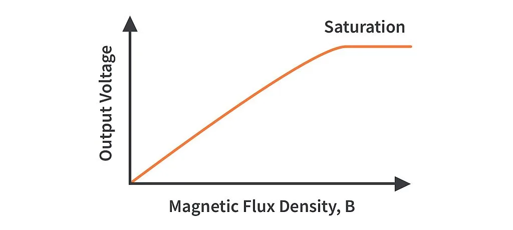
Hall effect sensors are classified based on their output, either analog or digital. The output signals for analog or linear hall effect sensors are taken directly from the output of the operational amplifier. The output in this case is directly proportional to the magnetic field passing through the sensor. The figure below shows how there is an increase in the output voltage of the amplifier with the increase in the magnetic field until it hits the saturation limits imposed on it because of the power supply.
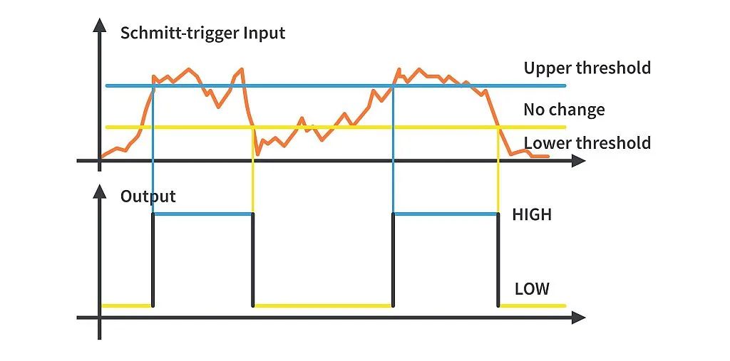
The analog output hall effect sensor can be converted into a digital output sensor with the addition of a Schmitt Trigger circuit at the output of the amplifier. The Schmitt trigger compares the output of the amplifier with its two preset or threshold values. If the input is higher than the upper threshold value, it outputs a logic high signal. If the input is below the lower threshold value, it outputs a logic low signal. When the input is between the two threshold values, the output retains its current value. This characteristic of the Schmitt trigger makes it possible to get digital signals as output from a hall effect sensor, a logic 0 or 1.
Applications
The robust design of hall effect sensors without any moving parts makes them maintenance-free as there is no wear and tear. They are also immune to vibration, dust, and water. This makes them a great choice for a variety of applications like:
- Brushless DC motors to detect the position of permanent magnets and switch currents accordingly.
- Rotary and shaft encoders to calculate RPM and detect the direction of motion.
- Current sensing in clamp meters.
- Sensing the angular position of the crankshaft for the firing of spark plugs in vehicles.
- Detect any surface without coming in contact with it.
