The induction motor is the most utilized electric motor in any industry that employs a rotary mechanism. Roughly 50% of global electric power produced is used to run induction motors. Electric locomotives, textile mills, compressors, pumps, fans, and even your hair drier – induction motors are just everywhere. Let’s understand the working principle of this amazing electrical machine.
The induction motor, like any motor, has a rotor - the rotating part, and a stator - the stationary part. The stator is shown in Figure 1.
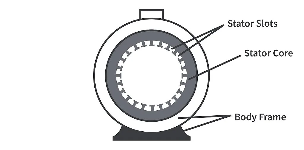
The stator core is laminated and fixed inside the body frame of the motor. The stator core has slots in the inner periphery to house the stator windings. The winding can be of one, two, or three phases. We will limit our discussion to 3 phase induction motors as it is easier to understand.
Consider a simplified stator structure as shown in Figure 2.
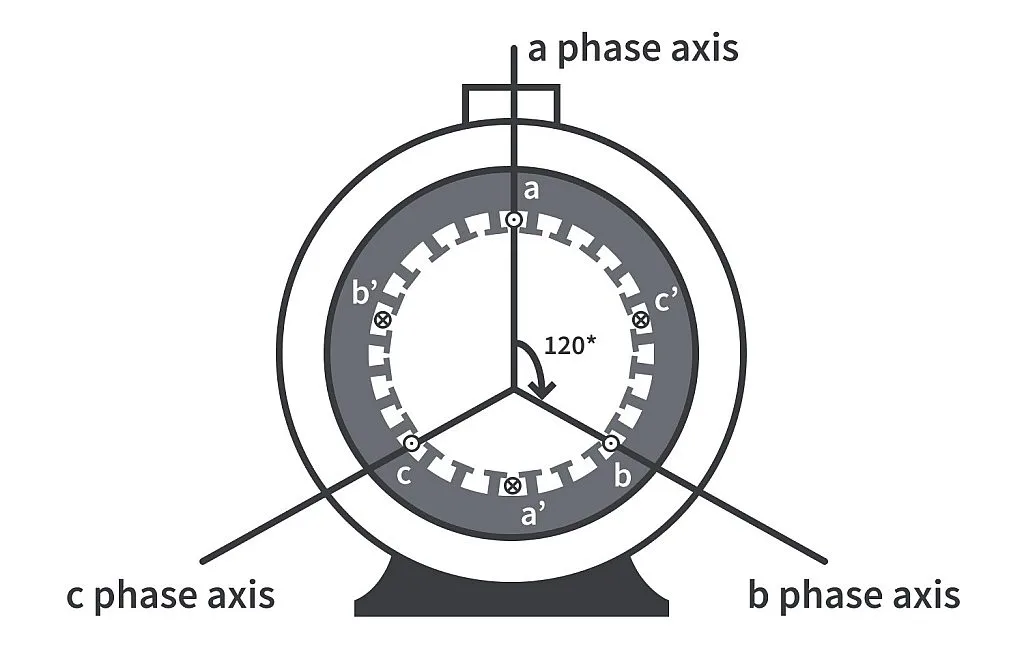
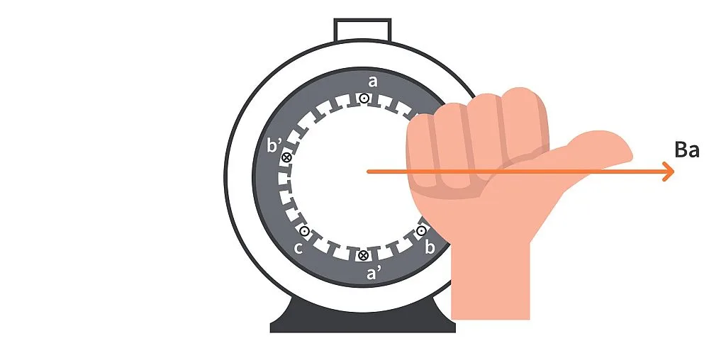
The windings of each phase are at 120° space displacement with each other. That is, the a phase axis is at 120° with both b phase and c phase axes. Since the windings are distributed in space, they are known as space distributed windings. If we were to energize the windings, one conductor of each phase will carry current out of the screen and one into the screen, hence the dot and cross markings. To find the direction of magnetic field produced by the a phase winding, we can make use of the right hand thumb rule. According to this rule, when we curl our fingers in the direction of current in a winding, the thumb points to the direction of the magnetic field produced by the current in the winding. Applying the rule on the conductors of a phase gives the direction of Ba - the magnetic field produced by the windings of a phase as shown in Figure 3.
The direction of magnetic field Bb and Bc of b and c phases respectively can be found out similarly by applying the right hand screw rule. They are as shown in Figure 4.
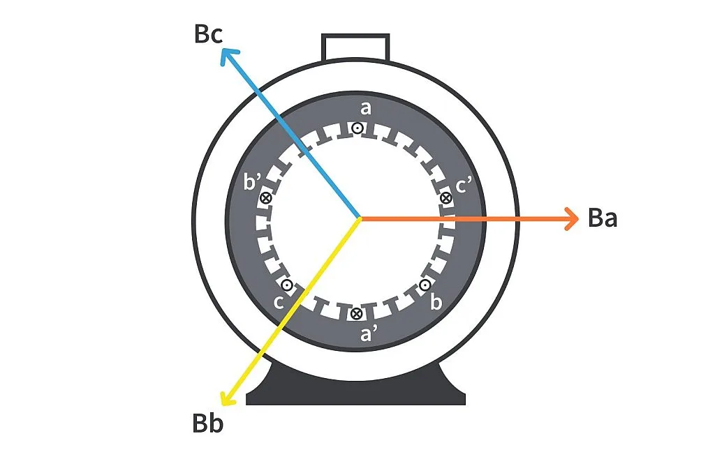
It should be noted that since the stator, and hence the stator windings, are stationary, the magnetic field produced by the windings is also stationary. They are confined to vary along the stationary axes. The magnitude of the magnetic field of a particular phase at any instant depends on the magnitude of current in the winding at that instant. The direction of the magnetic field on the other hand depends on the sense of voltage and hence the direction of current flow - if the current is negative, the direction of the magnetic field reverses. This can be seen in the GIF below.
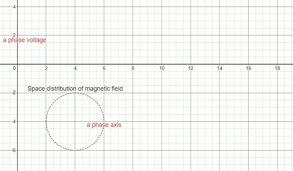
A 3 phase supply is a set of 3 voltages phase shifted by 120° - the voltages reach their peak 120° out of phase with each other. Energizing the windings of b and c phase gives rise to similar magnetic fields varying about their phase axes. This is shown in the GIF below.
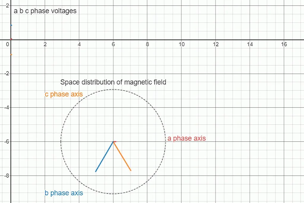
In a brilliant observation made by Nikola Tesla, he discovered that when a space-distributed 3 phase winding is energized with a time-shifted 3 phase supply, a single rotating magnetic field (abbreviated as RMF) is obtained due to the superposition of individual magnetic fields. To understand this graphically, refer to the image below.
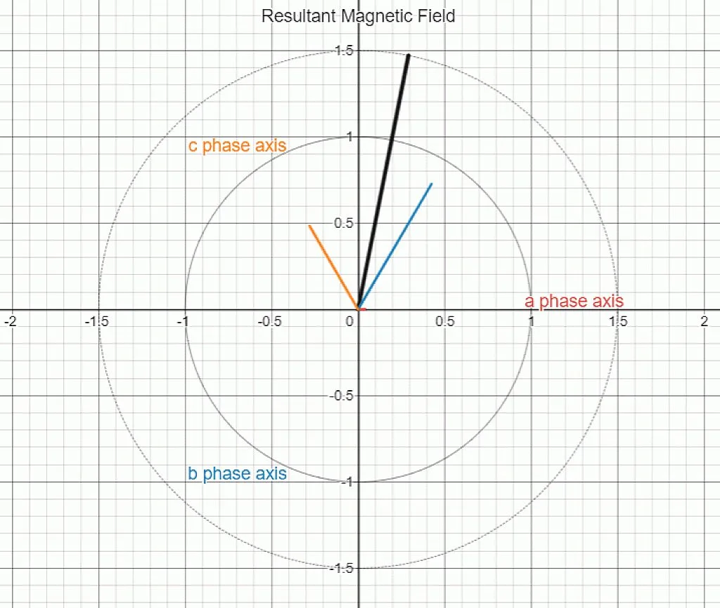
The black phasor (a phasor is a rotating vector) is actually the graphical summation of Ba, Bb and Bc. When we add the magnetic fields produced by phases a, b and c (which are stationary), we obtain a magnetic field which is rotating in space - the rotating magnetic field. Another observation which can be made at this point is that the magnitude of this rotating magnetic field is constant and it is 1.5 times the maximum magnetic field produced by any of the phases individually.
This rotating magnetic field rotates at a speed known as the synchronous speed Ns. The synchronous speed is a function of the frequency f of the stator supply and the number of poles P for which the stator winding is wound. The relation can be described as under:

Note that the stator is stationary here, but the rotating magnetic field is rotating at synchronous speed with respect to the stator.
Let’s discuss the rotor a bit now. The commonly used rotor is the squirrel cage type shown in Figure 5.
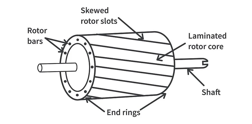
The rotor core has slots on the outer periphery and a shaft at the center. Each of the rotor slots houses a thick bar of metallic (usually aluminum or copper) conductor. The rotor bars of all slots are welded together on both ends with the help of two end rings, locking them in place rigidly and imparting an overall rugged structure to the rotor. The end rings, being conductors of electricity themselves, effectively short circuit all the rotor bars, and if an emf were to be induced in the bars, the current would flow in the rotor bars as it is a closed circuit. Without the rotor core, the rotor conductors and the end rings look like an empty squirrel cage - hence the name. The rotor bars are not straight but skewed for operational advantages which is beyond the scope of this discussion.
So far we have learned how the RMF is generated and have discussed the rotor. Now it's time to understand the motoring action which takes place in the induction motor.
Assuming the rotor is at rest initially, when the stator is energized from a 3 phase supply, the RMF produced by the resultant stator magnetic field sweeps across the stationary rotor conductors at synchronous speed cutting across the conductors. From Faraday’s law, whenever a conductor is placed in a magnetic field, an emf is induced in it. The RMF induces an emf in rotor conductors. The rotor, being a closed circuit, has a current flowing through the rotor conductors. As soon as this happens, the situation is similar to a current-carrying conductor experiencing electromagnetic force when placed in a magnetic field.
From Lenz's law, the direction of force should oppose the very cause producing it, which here is the relative velocity between the RMF and the stationary rotor conductors. The only way to oppose this induction of emf will be to reduce the relative velocity between the rotor and the RMF - the rotor starts to rotate in the direction of the RMF. This way the rotor tries to catch up with the rotating magnetic field.
Say the rotor does catch up with the RMF completely, now what? Due to the relative velocity being reduced to 0, the induction of emf ceases - no more current in the rotor conductors and hence no more electromagnetic force. The rotor starts to slow down and the whole action repeats itself. This is why the induction motor always runs at near synchronous speed but never at synchronous speed.
The appreciation of the popularity of the induction motor stems from the fact that the squirrel cage-type induction motor is the most rugged type of motor ever made. Unlike in DC motors, the induction motor doesn't need brushes or commutators. Once put into service, one can forget about the induction motor for a few years - it's that maintenance-free. This ingenious invention of Nikola Tesla revolutionized the entire manufacturing industry forever.
