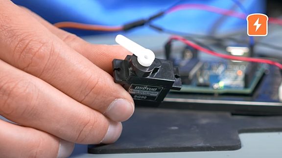
Direct current (DC) motors are used in all kinds of applications nowadays, from toys to robotics, but have you ever wondered how the speed and direction of the DC motor are controlled? For that, let’s suppose you have a DC motor and a battery. Now, to make the motor spin, you connect the battery's terminals to the DC motor, and the motor spins in a certain direction; reverse the polarity, and the motor spins in the other direction.

Now, what if we wanted to rotate the DC motor in different directions and at different speeds without having to manually swap the terminal wires? This is where the ‘H’ bridge circuit comes into action. This circuit switches the polarity of the voltage applied to the motor terminals as per the inputs we provide.
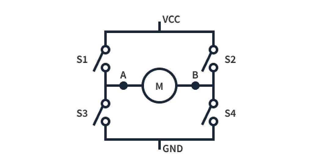
To understand the H bridge circuit, first, we need to understand the basic construction of this circuit. It has two branches with a total of four switches (S1, S2, S3, and S4), with each branch having two switches in series, and both branches are in a parallel connection. Motor terminals A & B are connected to the midpoints of the branches, with switches on either side of the terminal. The terminals of the motor act as a bridge between the branches and look like an ‘H’, hence the name of the circuit. Switches have only two digital states, ‘0’ and ‘1’, but the four switches together can give us many different combinations for the ‘H’ bridge circuit operation.
Below is a list of the different input combinations for our H-bridge circuit. ‘1’ represents that the switch is ON, and ‘0’ represents that the switch is OFF.
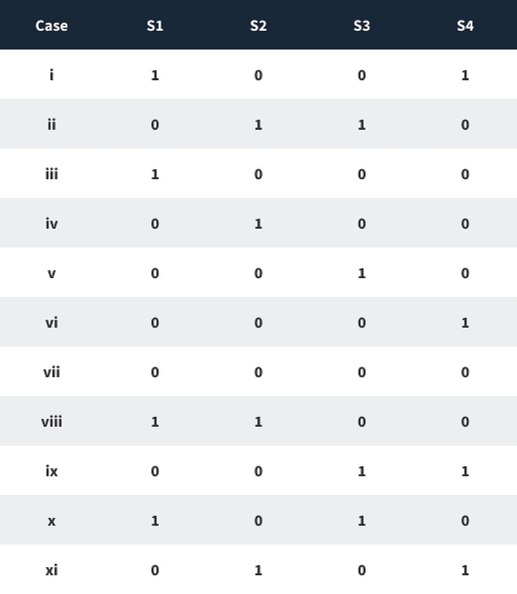
From all the combinations mentioned above, let’s first focus on the inputs which are used to spin the motor in different directions.
case i :
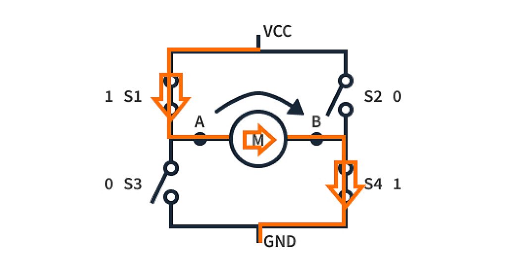
To rotate the motor, we need to establish a current flow through it. The direction of current flow determines the direction in which the motor rotates. So when switches S1 & S4 are closed, terminal A gets connected to VCC and terminal B to GND. This creates a potential difference on the two terminals of the motor, current starts to flow, and our motor rotates in the clockwise direction.
case ii
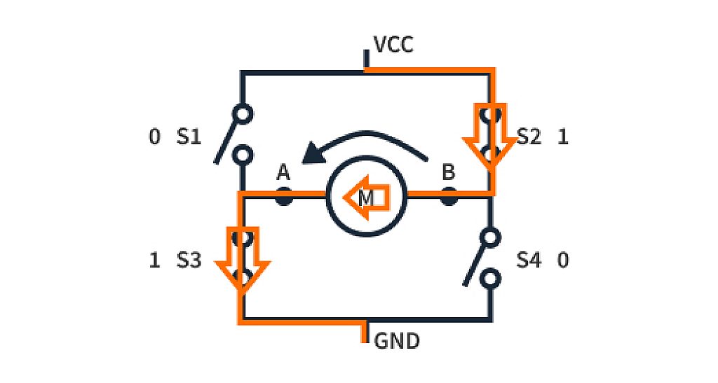
Now, what if we want to rotate the DC motor in the opposite direction? All we need to do is toggle specific switches such that the polarity on the motor terminals gets reversed. This can be achieved by closing switches S2 and S3, as shown in Figure 4. As the motor terminals experience opposite voltage polarity compared to case i, the motor starts to rotate in an anti-clockwise direction. Notice that we can now control the motor direction just by changing switches' positions without modifying the wire connections to the motor.
But wait, why consider these many cases if we just want to control the direction of the motor? Well, the remaining cases are very important when designing a control system for the DC motor, i.e. for position, velocity, torque, etc., which are some very important properties for an automatic system’s tuning and performance. Let’s now move on to other cases important for controlling such properties of a motor.
case iii, iv, v, vi, vii
For these input conditions, at least one of the motor terminals lacks a connection to either VCC or GND, which means there is no path for current to flow, and no magnetic field is induced in the motor. In this case, the motor is in a state called “coasting”; that is, it rotates freely in the direction it’s rotating and comes to rest eventually due to friction or remains steady if it is not rotating. An even simpler explanation for "coasting" would be: cutting off the power to the motor so that it comes to rest automatically in some time due to the resistances that oppose the motor’s motion.
Now we know that coasting ultimately brings the motor to rest, but that still takes a few seconds. What if we want our motor to stop rotating immediately, in less than a second? This is where the next cases are used.
case viii, ix
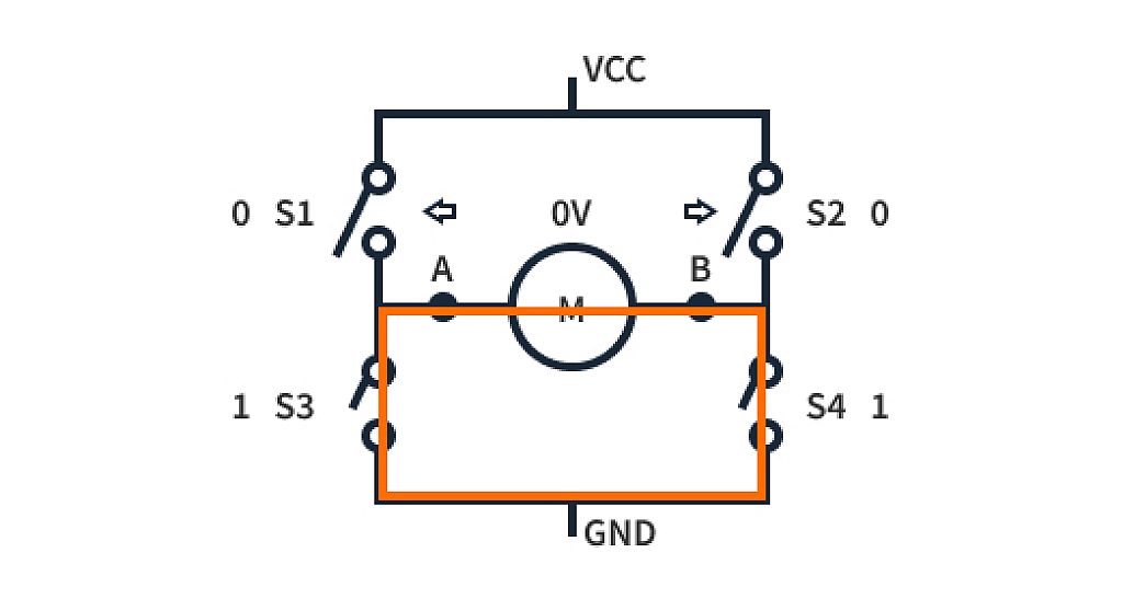
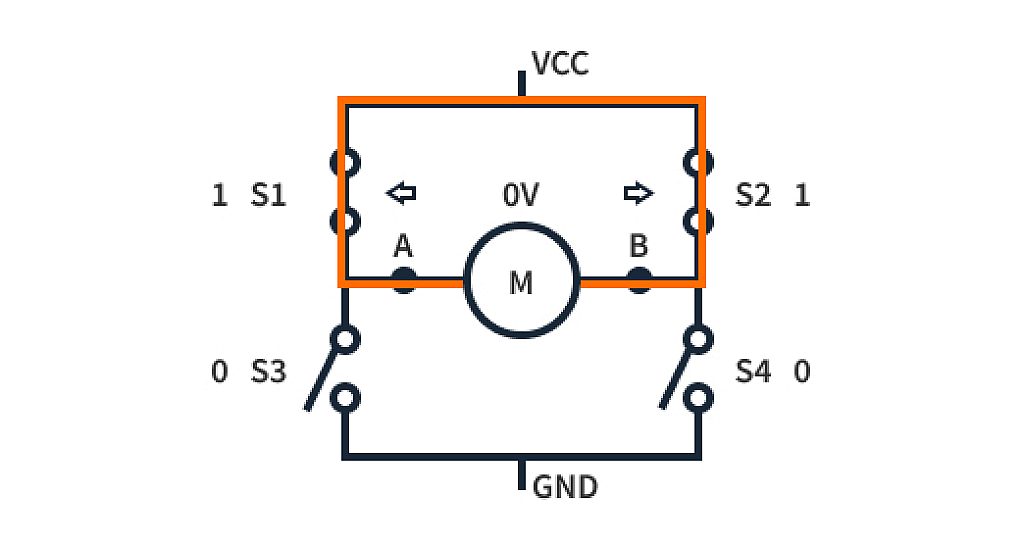
The above conditions are used for the instantaneous braking of the running motor. It is referred to as “power braking”. Applying the same potential to both the terminals of the motor, it is forced to maintain a potential difference of 0V across its ends, causing short circuit damping to slow down the running motor.
case x, xi
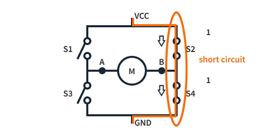
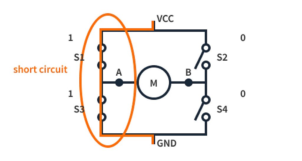
The previously discussed cases were all about the motion of the motor, but cases x and xi can be dangerous for the system. These conditions close the switches in series, causing a short circuit between VCC and GND, which is never a good idea. Hence, these cases should be avoided.
Now that we know about all the conditions of the “H” bridge, we can move forward to controlling the speed of the motor. Suppose we have a DC motor with an operating voltage of 12V, and if we apply a 12V potential difference across its terminals, the motor will spin at its maximum speed. If we change the potential difference to 6V, the motor will spin at half its maximum speed. So we know that to change the speed of the motor, we just need to vary the applied voltage across its terminals. We can achieve this in our H-bridge circuit if we replace the regular switches with electronic switches that can control the output voltage. For instance, if we take MOSFETs as switches, we can control the output voltage by applying a PWM signal to the gate of the MOSFETs, which a microcontroller will generate. Hence, by applying PWM signals of different duty cycles, the output voltages of the MOSFETs can be changed, and we can control the speed of the motor along with the directions.
We hope now you can understand why H-bridge circuits are extremely popular among electronics hobbyists. Their simplicity makes them a good choice for anyone starting with practical electronics. To make things even simpler, we can pair up the switches of our H-bridge motor driver with a microcontroller and can easily control the operation with digital signals.
