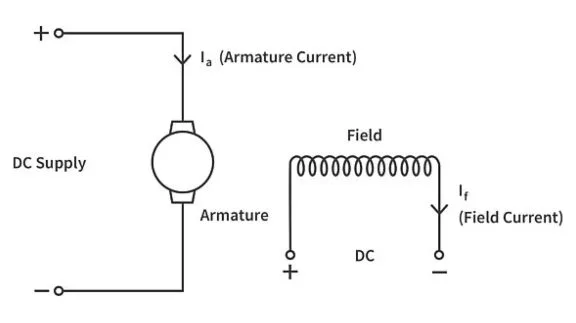
Regenerative braking is a form of electric braking wherein the kinetic energy of the load is converted to electrical energy which is used to feed energy back to the supply. To understand how regenerative braking works, let us quickly review the operation of a DC motor.
Consider a DC motor disconnected from a power supply as shown in figure below.

To produce the motoring action, the DC motor is connected across a voltage supply which causes a current to flow into the motor conductors. Assume a current coming out (dot) of the paper in the conductors under the north pole. Naturally, the conductors under the south pole will have a current into (cross) the paper.

Whenever a current-carrying conductor is placed in a magnetic field, it experiences an electromagnetic force. Here the conductor is under the influence of the field system of the DC motor and hence it experiences an electromagnetic force. Applying Fleming's left-hand rule, we see that an electromagnetic force is towards the right on the top conductors and towards the left on the bottom conductors. These forces produce a net electromagnetic torque Te on the motor in the clockwise direction as seen in the figure below. Note that the force produced on the conductors is sensitive to the direction of current. Reversing the current reverses the direction of electromagnetic force and hence the direction of the electromagnetic torque.

As the machine starts rotating, the conductors also rotate in the magnetic field. Whenever a conductor moves in a magnetic field, an emf is induced in the conductor. Applying Fleming’s right-hand rule, we can see that the direction of induced emf is into the paper (cross) as shown in the figure below. This induced emf, known as the back emf (Eb), is proportional to the speed of the motor ( ω ).


The direction of induced emf opposes the current originally flowing in the conductor. To keep the electromagnetic torque unidirectional and for the motoring action to continue, the terminal voltage should be high enough to overcome this back emf and be able to drive the required current. The terminal voltage is chosen such that it is well above the back emf throughout the normal range of operating speed.
Sometimes the motor speed may increase above the rated speed – this usually happens when the load itself drives the motor like in the case when a loaded hoist is being lowered or a vehicle is moving downhill (Load torque TL > Te ). At speeds above the rated speed, the back emf is greater than the terminal voltage. The back emf will now drive the current through the armature conductors in the reverse direction. Reversing the direction of the current reverses the electromagnetic torque which will now oppose the load torque.

With the armature current reversed in the conductors, the total armature current also reverses and flows back to the supply hence feeding it. The DC motor is now acting as a generator.
Let us now apply the above principles to regenerative braking. Consider the scenario when the vehicle is traveling at rated speed on a flat road just before a downhill road ahead. The vehicle will start to accelerate as it travels downhill - the motor speed will exceed the value of rated speed. The machine's shaft continues rotating in the forward direction due to the kinetic energy of the vehicle moving downhill. Back emf increases above the terminal voltage and the armature current reverses direction, the direction of electromagnetic torque Te also reverses direction on reversal of current direction. Te now opposes load torque TL and provides the braking action. The reversed armature current feeds energy back to the supply which in this case is the battery pack of the vehicle – the vehicle regenerates.
Say, due to the braking operation, there is a point on the same downhill road when the speed has decreased below the rated value. As the speed decreases below the rated speed, back emf decreases too, and it becomes less than the terminal voltage, the regenerative braking action ceases and the motor again starts to drive the load. To ensure this does not happen, the back emf is boosted using a boost converter-like arrangement. Boosting back emf keeps the current direction undisturbed and hence the braking torque. The same approach is used to obtain regenerative braking at speeds less than rated speed on levelled roads as well. However, at very low speeds, the electromagnetic torque is not enough to provide the required braking torque and the friction brakes need to be activated.
By using simple operating principles of a DC machine, not only did we obtain the braking action, but also utilized the kinetic energy of the vehicle to feed energy back to the supply. Regenerative braking is highly energy efficient compared to the conventional braking system where the brake shoes apply frictional force on wheels to produce the braking action and the kinetic energy of the load is dissipated as heat in the brake shoe arrangement.


