Digital Clock using RTC and OLED Display | Renesas RA - 9
Published
Hi again! This tutorial will summarize everything we’ve studied before and join it all in this application. The task for today is the following: create a digital and analog clock using the internal RTC module of the RA2A1 MCU and the OLED display, set the time and date using the user button S1 to select the value, and the touch button TS1 to change the value.
So, as you see, we will use the mechanical button (tutorial 5), touch button (tutorial 6), and OLED display (tutorial 8). The only new module to study is the RTC but it’s quite simple.
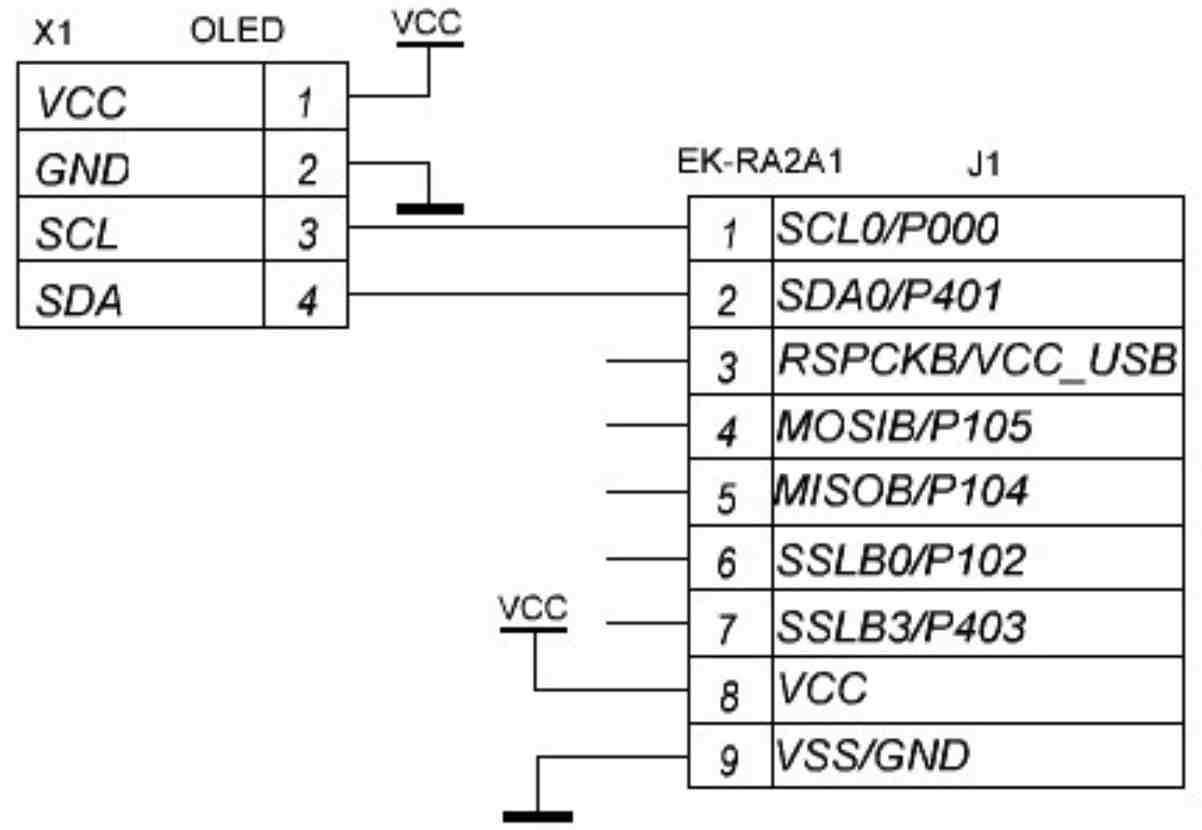
The schematic diagram of the device is exactly the same as in tutorial 8 because all other elements are located on the board (Figure 1).
Project Configuration
Let’s now create a new project based on the C++ language like I told you in tutorial 8.
The first thing we need to do is to configure the touch module “rm_touch” like I told you in tutorial 6. I don’t know why it is so but when I configured the touch interface after other modules, the program hung during the touch module initialization: it seemed like its interrupts never happened. Yet when I configured it first in the project, everything worked perfectly even though the code and the FSP configuration were the same, so this may be considered as an unknown but solvable issue.
As for the regular button S1, we don’t need to configure anything with it, as this time we will not use the GPIO interrupt and process the button inside the main loop.
Next, we need to configure the OLED display exactly like we did in tutorial 8. But this time you can use the already ported library from the previous experience and not change it again. Don’t forget about the following points:
- Configure the IIC0 pins;
- Add and configure the IIC0 stack;
- Increase the heap size from 0 to 0x1000;
- Copy and paste the “Adaruit_GFX” and “Adafruit_1306” folders to the “src” folders;
- Add these folders to the “includes”;
- Exclude the unnecessary folders and files from build.
Next, you can try to build your project and make sure that there are no errors. And if there are, try to get rid of them by reading the previous tutorials more carefully.
Now we need to configure the RTC module of the MCU. Actually, we could use an external RTC chip like the popular DS1307 or DS1302 but why do this if the RA2A1 MCU has a fully functional inbuilt module? Let’s quote the RA2A1 User’s Manual and provide the main functions of the RTC (Figure 2).
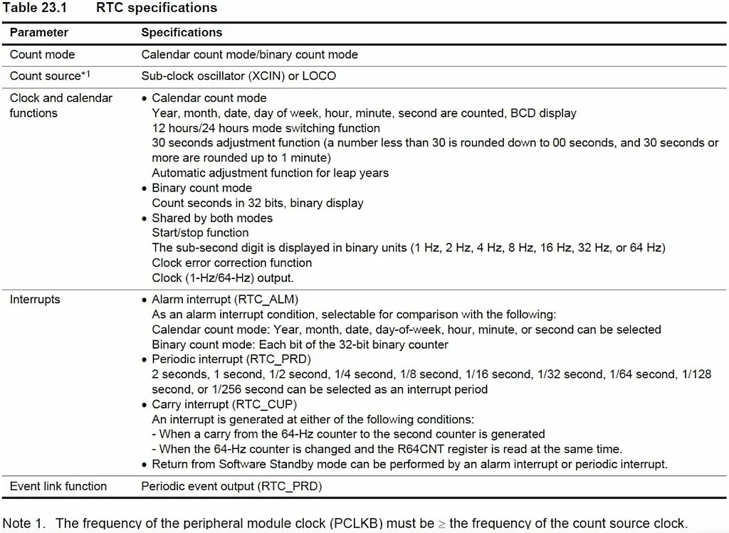
As you can see, this module can work in a binary mode, like a seconds counter, or in a calendar mode, in which it counts seconds, minutes, hours, days, days of week, months, and years. Also, it can generate periodic interrupts with specified periods (see Figure 2), and alarm interrupts at a specified day and time.
In our program we will use the calendar mode and periodic interrupts.
Also you can see in Figure 2 that the RTC can be clocked either with the LOCO or with the Sub-Clock source. LOCO is the Low-Speed On-Chip Oscillator, it has the frequency of 32768 Hz but its initial accuracy is only 15% which is not good for driving a clock. So we will use the Sub-Clock source. This is the oscillator which uses the external crystal with the same frequency of 32768 Hz.
In the EK-RA2A1 board there is a crystal X2 connected to pins P214 (XCOUT) and P215 (XCIN). By default these pins are configured as a GPIO so we need to reconfigure them to be used by the Sub-Clock oscillator.
To do this we need to open the “Pins” tab of the FSP Configurator, scroll down to the “Peripherals” list, find the sublist “System: CGC”, and select the line “CGC0”. CGC here stands for Clock Generator Controller (Figure 3).
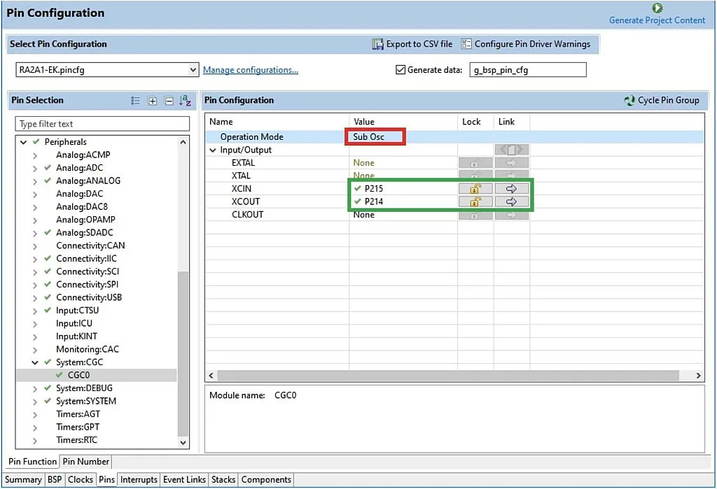
In the “Operation Mode” field we need to select the “Sub Osc” from the drop-down list, and then make sure that XCIN and XCOUT pins have changed from “None” to P215 and P214, respectively. Also you can select here the Main Clock, in this case the 12 MHz crystal will be connected to the pins EXTAL and XTAL. We will use it when we need some high-frequency and high-accuracy clock source but for now we’re fine. Also here you can select the CLKOUT pin, through which the clock signal can be output.
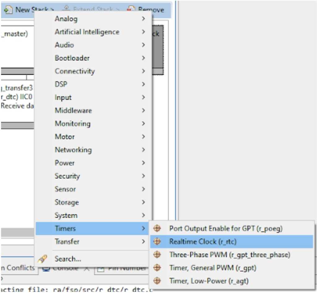
Now we need to switch to the “Stacks” tab, click on the “New Stack >” button, expand the “Timers” list and select the “Realtime Clock (r_rtc)” (Figure 4).
Then click on the “g_rtc0 Realtime Clock (r_rtc)” block and adjust its properties according to Figure 5.

- “Set Source Clock in Open” theoretically allows us to not call the R_RTC_ClockSourceSet function which sets the clock source of the RTC. But in fact this function isn’t invoked in the R_RTC_Open function regardless of the value in this line. I guess this is some bug in the FSP, maybe just in the current 3.7.0 version.
- The “Clock Source” field can have two values: LOCO and Sub-Clock. As I mentioned before, we will use the “Sub-Clock” source, so we need to select this option.
- The “Frequency Comparison Value (LOCO)” field is used only when the LOCO is used as the clock source. This is the value by which the LOCO frequency should be divided to get the basic RTC frequency of 128 Hz.
- The “Automatic Adjustment Mode” field allows the automatic adjustment of the crystal frequency which we will not use as we don’t know the exact crystal frequency. I will skip the explanation of the other adjustment-related fields, you can read more detail about them in the RA2A1 User’s Manual.
- The “Callback” field is the name of the RTC callback function. As I said, we will use it for periodic interrupts.
- The next three fields enable the Alarm, Periodic, and Carry interrupts and set their priority. We need to enable the Periodic Interrupt. The Carry interrupt (see Figure 2) can’t be disabled.
These are all settings we need to do for the current project, so now we can click on the “Generate Project Content” button and switch to the “hal_enty.cpp” file to write the program code.
Program Code
#include "hal_data.h"
#include "Adafruit_SSD1306.h"
#include "Fonts/FreeSans9pt7b.h"
#include <stdio.h>
#include <math.h>
#include "qe_touch_config.h"


FSP_CPP_HEADER
void R_BSP_WarmStart(bsp_warm_start_event_t event);
FSP_CPP_FOOTER


#define DEBOUNCE_DELAY 20       	//Debounce delay of 20 ms for the button


Adafruit_SSD1306 display(128, 64);  //OLED display object creation
rtc_time_t my_time=             	//Time structure with the initial values
{
    .tm_sec  = 0,
    .tm_min  = 0,
    .tm_hour = 0,
    .tm_mday = 1,
    .tm_mon  = 1,
    .tm_year = 100,
};
char str[11];                   	//String to be sent to OLED
uint8_t x0, x1, x2, y0, y1, y2; 	//Coordinates of the points
volatile uint32_t tick_1_128;   	//1/128 of second ticks counter
uint64_t button_status;         	//Touch buttons status
uint8_t previous_status;        	//Touch button previous status


enum modes                      	//Modes of operation of the clock
{
    MODE_NORMAL,
    MODE_SET_SECOND,
    MODE_SET_MINUTE,
    MODE_SET_HOUR,
    MODE_SET_DAY,
    MODE_SET_MONTH,
    MODE_SET_YEAR
};
modes mode = MODE_NORMAL;       	//Current mode is normal


fsp_err_t err;                  	//Result of the FSP API functions operation


void rtc_periodic_callback(rtc_callback_args_t *p_args) //RTC callback function
{
    if (p_args->event == RTC_EVENT_PERIODIC_IRQ)//If it is the periodic interrupt
        tick_1_128 ++;          	//Increment the tick counter
}


/*******************************************************************************************************************//**
* main() is generated by the RA Configuration editor and is used to generate threads if an RTOS is used.  This function
* is called by main() when no RTOS is used.
**********************************************************************************************************************/
void hal_entry(void)
{
    err = RM_TOUCH_Open(g_qe_touch_instance_config01.p_ctrl, g_qe_touch_instance_config01.p_cfg);//Initialize the touch interface
    if (FSP_SUCCESS != err) //If result is not successful
    {
        while (true) {} //Then hang the program here
    }
    R_BSP_SoftwareDelay(1, BSP_DELAY_UNITS_SECONDS);// Perform 1 second delay to let the OLED power stabilize
    display.begin(SSD1306_SWITCHCAPVCC, 0x3C, false, true); //Initialize OLED display with the I2C addr 0x3C (for the 128x64)
    R_RTC_Open(&g_rtc0_ctrl, &g_rtc0_cfg);  //Initialize the RTC module
    R_RTC_ClockSourceSet(&g_rtc0_ctrl); 	//Set the clock source of the RTC (also sets 24 hour format)
    R_RTC_CalendarTimeSet(&g_rtc0_ctrl, &my_time);//Assign the RTC with the initial values
    R_RTC_PeriodicIrqRateSet(&g_rtc0_ctrl, RTC_PERIODIC_IRQ_SELECT_1_DIV_BY_128_SECOND); //Set the RTC periodic interrupt period
    display.begin(SSD1306_SWITCHCAPVCC, 0x3C, false, true); //Initialize OLED display with the I2C addr 0x3C (for the 128x64)
    display.setFont(&FreeSans9pt7b);	//Set the font name
    display.setTextColor(WHITE);    	//Set text color
    /* Main loop */
    while (true)
    {
        if (tick_1_128 % 4 == 0) //Every 31.25 ms
        {
            err = RM_TOUCH_ScanStart(g_qe_touch_instance_config01.p_ctrl); //Start touch button scanning
            if (FSP_SUCCESS != err) //If result is not successful
            {
                while (true) {}  //Then hang the program here
            }
            while (0 == g_qe_touch_flag) {} //Wait while the scanning is done
            g_qe_touch_flag = 0;	//And reset the flag


            err = RM_TOUCH_DataGet(g_qe_touch_instance_config01.p_ctrl, &button_status, NULL, NULL); //Get the state of the touch button
            if (FSP_SUCCESS == err)
            {
                if ((button_status == 1) && (previous_status == 0))   //If the current button state is low and previous state is high
                    previous_status = 1;  //We reset the previous state to 0 to prevent implementation of this branch the next time
                else if ((button_status == 0) && (previous_status == 1))   //If the current button state is high and previous state is low
                    previous_status = 0; //Then we set the previous state as 1 to prevent implementation of this branch the next time
                else if ((button_status == 1) && (previous_status == 1)) //If both states are high (button is held touched)
                {
                    if ((tick_1_128 % 32) == 0) //Every 250 ms
                    {
                        switch (mode)       	//Select the mode
                        {
                            case MODE_NORMAL: break;//If mode is normal, do nothing
                            case MODE_SET_SECOND:   //If mode is set_second
                                my_time.tm_sec ++;  //Then increase the second
                                if (my_time.tm_sec > 59)//If the second is greater than 59
                                    my_time.tm_sec = 0;//Then set the second as 0
                                break;
                            case MODE_SET_MINUTE:   //If mode is set_minute
                                my_time.tm_min ++;  //Then increase the minute
                                if (my_time.tm_min > 59)//If the minute is greater than 59
                                    my_time.tm_min = 0;//Then set the minute as 0
                                break;
                            case MODE_SET_HOUR: 	//If mode is set_hour
                                my_time.tm_hour ++; //Then increase the hour
                                if (my_time.tm_hour > 23)//If the hour is greater than 23
                                    my_time.tm_hour = 0;//Then set the hour as 0
                                break;
                            case MODE_SET_DAY:  	//If mode is set_day
                                my_time.tm_mday ++; //Then increase the day
                                if (my_time.tm_mday > 31)//If the day is greater than 31
                                    my_time.tm_mday = 1;//Then set the day as 1
                                break;
                            case MODE_SET_MONTH:	//If mode is set_month
                                my_time.tm_mon ++;  //Then increase the month
                                if (my_time.tm_mon > 12)//If the month is greater than 12
                                    my_time.tm_mon = 1;//Then set the month as 1
                                break;
                            case MODE_SET_YEAR: 	//If mode is set_year
                                my_time.tm_year ++; //Then increase the year
                                if (my_time.tm_year > 199)//If the year is greater than 199 (2099)
                                    my_time.tm_year = 100;//Then set the year as 100 (2000)
                                break;
                        }
                    }
                }
            }
        }


        if ((tick_1_128 % 32) == 0) //Every 250 ms
        {
            if (mode == MODE_NORMAL) //If the mode is normal
                R_RTC_CalendarTimeGet(&g_rtc0_ctrl, &my_time); //Then read the time from the RTC module
            display.clearDisplay(); //Clear the display
            //Draw analog clock face
            display.drawCircle(32, 32, 31, WHITE);
            for (int16_t i = 0; i < 360; i += 30)
                display.drawLine((31*sin(i / 57.296)) + 32, (31*cos(i / 57.296)) + 32, (27*sin(i / 57.296)) + 32, (27*cos(i / 57.296)) + 32, WHITE);
            //Draw the seconds arrow
            x0 = 32+((26*sin(my_time.tm_sec * 6 / 57.296)));
            y0 = 32-((26*cos(my_time.tm_sec * 6 / 57.296)));
            display.drawLine(32, 32, x0, y0, WHITE);
            //Draw the minutes arrow
            x0 = 32+((2*cos(my_time.tm_min * 6 / 57.296)));
            y0 = 32+((2*sin(my_time.tm_min * 6 / 57.296)));
            x1 = 32-((2*cos(my_time.tm_min * 6 / 57.296)));
            y1 = 32-((2*sin(my_time.tm_min * 6 / 57.296)));
            x2 = 32+((25*sin(my_time.tm_min * 6 / 57.296)));
            y2 = 32-((25*cos(my_time.tm_min * 6 / 57.296)));
            display.drawTriangle(x0, y0, x1, y1, x2, y2, WHITE);
            //Draw the hours arrow
            x0 = 32+((2*cos((my_time.tm_hour * 30 + my_time.tm_min / 2) / 57.296)));
            y0 = 32+((2*sin((my_time.tm_hour * 30 + my_time.tm_min / 2) / 57.296)));
            x1 = 32-((2*cos((my_time.tm_hour * 30 + my_time.tm_min / 2) / 57.296)));
            y1 = 32-((2*sin((my_time.tm_hour * 30 + my_time.tm_min / 2) / 57.296)));
            x2 = 32+((18*sin((my_time.tm_hour * 30 + my_time.tm_min / 2) / 57.296)));
            y2 = 32-((18*cos((my_time.tm_hour * 30 + my_time.tm_min / 2) / 57.296)));
            display.fillTriangle(x0, y0, x1, y1, x2, y2, WHITE);
            //Write the time
            display.setCursor(58, 13);
            sprintf(str,"%02d:%02d:%02d", my_time.tm_hour, my_time.tm_min, my_time.tm_sec);
            display.print(str);
            //Write the day and month
            sprintf(str,"%02d.%02d", my_time.tm_mday, my_time.tm_mon);
            display.setCursor(70, 36);
            display.print(str);
            //Write the year
            sprintf(str,"%04d", my_time.tm_year + 1900);
            display.setCursor(70, 61);
            display.print(str);


            switch (mode)   //In different modes draw the rectangle around the value to be changed
            {
                case MODE_NORMAL: break;
                case MODE_SET_SECOND: display.drawRoundRect(107, 0, 22, 16, 2, WHITE); break;
                case MODE_SET_MINUTE: display.drawRoundRect(82, 0, 22, 16, 2, WHITE); break;
                case MODE_SET_HOUR: display.drawRoundRect(57, 0, 22, 16, 2, WHITE); break;
                case MODE_SET_DAY: display.drawRoundRect(69, 23, 22, 16, 2, WHITE); break;
                case MODE_SET_MONTH: display.drawRoundRect(94, 23, 22, 16, 2, WHITE); break;
                case MODE_SET_YEAR: display.drawRoundRect(69, 48, 42, 16, 2, WHITE); break;
            }


            display.display(); //Flush the buffer to the display
        }


        if (R_BSP_PinRead(BSP_IO_PORT_02_PIN_06) == BSP_IO_LEVEL_LOW) //If button is pressed
        {
            R_BSP_SoftwareDelay(DEBOUNCE_DELAY, BSP_DELAY_UNITS_MILLISECONDS); //Debounce delay
            if (R_BSP_PinRead(BSP_IO_PORT_02_PIN_06) == BSP_IO_LEVEL_LOW)   //If button is still pressed
            {
                while (R_BSP_PinRead(BSP_IO_PORT_02_PIN_06) == BSP_IO_LEVEL_LOW);//Wait while button is pressed
                R_BSP_SoftwareDelay(DEBOUNCE_DELAY, BSP_DELAY_UNITS_MILLISECONDS);//Debounce delay
                if (R_BSP_PinRead(BSP_IO_PORT_02_PIN_06) == BSP_IO_LEVEL_HIGH) //If button is released
                {
                    if (mode == MODE_SET_YEAR) //If current mode is set_year
                    {
                        mode = MODE_NORMAL;  //Then set mode as normal
                        R_RTC_CalendarTimeSet(&g_rtc0_ctrl, &my_time); //And update the RTC module values
                    }
                    else //Otherwise
                        mode = static_cast<modes>(mode + 1); //Set the next mode
                }
            }
        }
    }
#if BSP_TZ_SECURE_BUILD
    /* Enter non-secure code */
    R_BSP_NonSecureEnter();
#endif
}
In lines 1-6 we include the required header files:
- “hal_data.h” - added automatically.
- “Adafruit_SSD1306.h” - to use the OLED display.
- “Fonts/FreeSans9pt7b.h" - the header to the font which we will use to write the text. This file is located in the “Adafruit-GFX-Library-master/Fonts” folder along with a lot of other fonts which we can use. The structure of the header file is the following: font name (FreeSans), height (9pt), width (7b) of the character. You can select whichever font you like the most. There are also some changes needed to be done in the font header file, but I’ll talk about them later.
- “stdio.h” - to use the sprintf function.
- “math.h” - to use trigonometric functions.
- “qe_touch_config.h” - to use the touch button. As you can see, here we don’t write the main code inside the “qe_touch_sample.c” file like we did in tutorial 6. Moreover, we need to exclude this file from build to avoid the double declaration error.
In line 12 we define the DEBOUNCE_DELAY macro, needed in processing the mechanical button.
In line 14 we create the object of the Adafruit_SSD1306 class, called display.
In line 15 we declare the variable my_time of the rtc_time_t type. This type is used to store the time and date. In lines 17-22 we initialize the fields of my_time with the default time 00:00:00 and date 01.01.2000. Please pay attention that in the tm_year field we write the value 100 because this type counts the years starting from 1900 so the value 100 will correspond to 1900 + 100 = 2000.
In line 24 we declare the str variable which is an array of 11 char elements. It will be used in the function sprintf to convert the number into the string to send to the LCD.
In line 25 we declare six variables x0, x1, x2, y0, y1, y2 which are the coordinates of the points to draw some figures in the display.
In line 126 we declare the tick_1_128 variable which is the counter of the 1/128 of second intervals that will be produced by the RTC periodic interrupts.
In lines 127 and 128 we declare variables button_status and previous_status which are used to process the touch button like we did in tutorial 6.
In lines 30-39 we create the enumerated type modes which represent the modes in which the clock can work. In the MODE_NORMAL the clock works as usual and displays the time and date. In all other modes we set the corresponding value. For example, in MODE_SET_SECOND we can manually set the second value and then save it into the RTC. In line 40 we declare the mode variable of this enumerated type.
Finally, in line 42 we declare the err variable of type fsp_err_t which will consist of the result of the FSP-generated functions.
In lines 44-48 there is the RTC callback function. If you remember we gave it the name rtc_periodic_callback during the RTC stack configuration (Figure 5). Inside this function we check if the event that caused this callback is RTC_EVENT_PERIODIC_IRQ (line 46), and if it is, then we increment the tick_1_128 variable (line 47).
In lines 54-213 there is the main function of the program hal_entry.
The initialization part of the program occupies lines 56-68. In line 56 we open the touch interface and apply the configuration to it by calling the RM_TOUCH_Open function. If the result of this function was not successful (line 57) then we hang the program forever at this point (line 59). In line 61 we implement a 1 second delay to let the display voltage regulator stabilize.
In line 62 we perform the display initialization (for more information about this function please refer to tutorial 8).
In line 63 we open the RTC interface and apply the configuration to it. In line 64 we call the function R_RTC_ClockSourceSet to set the RTC clock source and also to switch to 24-hour format. As I said before, this function should’ve been invoked in the R_RTC_Open function but for some reason this doesn’t happen. In line 65 we assign the RTC date and time with the initial values defined in lines 17-22. In line 66 we set the period of the RTC periodic interrupts as RTC_PERIODIC_IRQ_SELECT_1_DIV_BY_128_SECOND which name speaks for itself. This is all about initialization of the RTC module.
In line 67 we initialize the display the same as we did in tutorial 8. In line 68 we set the font which we will use to write the text. You may notice that the name of the font corresponds to the name of the header file in line 3. In line 69 we set the color of the text as WHITE. This is needed to make the text visible.
In lines 71-208 there is the main loop of the program.
In line 73 we check if the modulo of division of the tick_1_128 by 4 is 0. This condition becomes true every (1 / 128) x 4 x 1000 = 31.25 ms. Inside this branch we scan and process the touch button. Actually this part is the same as in tutorial 6, so I will not describe it once more here. Instead I will talk in more detail about the payload of the touch button pressing (lines 92-128).
This branch, as you can see in line 90 is active while we hold the touch button. Here we will adjust the time and date of the RTC. In line 92 we check if the modulo of division of the tick_1_128 by 32 is 0, which happens every 250 ms. So while the button is held, the corresponding value will be increased 4 times per second.
In lines 94-127 there is the switch construction to check all the modes. In the normal mode (line 96) we do nothing, as there is no selected value to change.
In the MODE_SET_SECONDS (line 97) we increment the second value at every iteration (line 98). If it becomes greater than 59 (line 99) we reset it to 0 (line 100). In the same way we adjust the minutes (lines 102-106), hours (lines 107-111), days (lines 112-116), months (lines 117-121) and years (lines 122-126).
In lines 133-187 we update the display every 250 ms (which is checked in line 133). First, if the mode is MODE_NORMAL (line 135) we read the time and date from the RTC (line 136). Then we clear display (line 137) not to leave the artifacts from the previous time. In lines 139-161 we draw the analog clock, and in lines 163-173 we write the time and date with the formerly selected font. Let’s consider them in more detail.
In line 139 we draw the circle with the center at coordinates (32, 32) and radius of 31. The beginning of the coordinates is the top left corner. In line 140 we make the loop draw 12 dashes around the circle like in a typical analog clock. They are drawn by the method drawLine (line 141) which accepts the coordinates of the first and the second dots of the line. To understand line 141 we need to recall our school course in geometry (Figure 6).
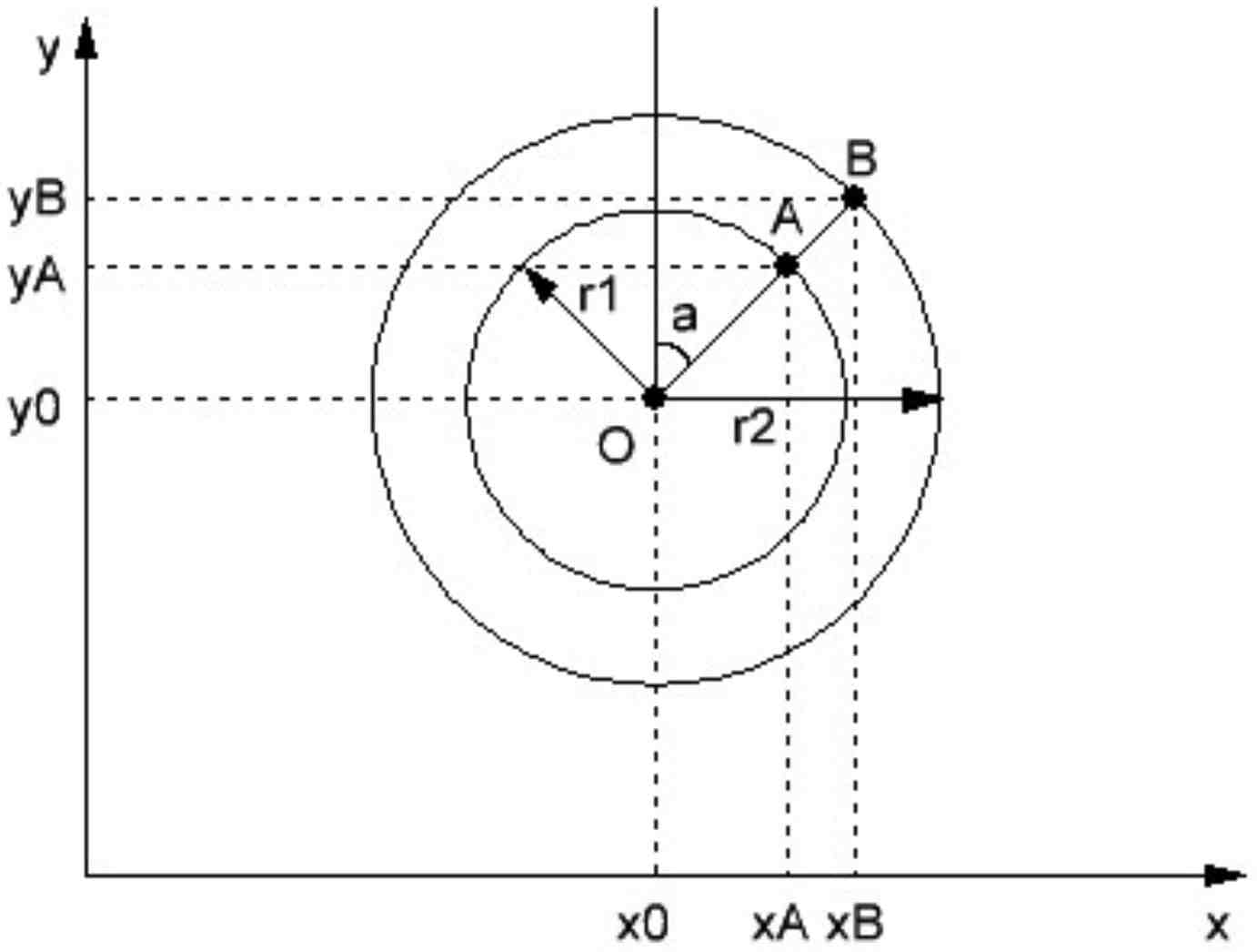
As you hopefully remember, the coordinates of each point at the circle can be calculated as:
(xA - x0) = r1 sin(a);
(yA - y0) = r1 cos(a);
(xB - x0) = r2 sin(a);
(yB - y0) = r2 cos(a).
From where:
xA = x0 + r1 sin(a);
yA = y0 + r1 cos(a);
xB = x0 + r2 sin(a);
yB = y0 + r2 cos(a).
In our case x0 = y0 = 32, r1 = 27, r2 = 31. The angle a is variable and changes from 0 to 330 degrees with the step of 30 degrees. As the trigonometric functions in C language accept the arguments in radians, we need to convert the degrees to radians. To do this we need to remember that 180 degrees correspond to π radians, so 1 radian is 180 / π ≈ 57.296, that’s why we divide the argument of the trigonometric functions by this number.
In lines 143-144 we draw the seconds arrow which is just a line from the center of the circle with the radius of 26. The formula of the coordinate at the circle surface is the same but the attentive reader may notice that in line 44 the sign is minus instead of plus. This is not a mistake. The thing is that the beginning of the coordinates is top left corner but not bottom left as in Figure 6. That’s why we need to negate the y coordinate. When we drew the clock face it didn’t matter because it’s symmetrical, but for arrows this is crucial not to get the mirrored clock.
The minute and hour arrows will be drawn as triangles: the first one will be longer and not filled, and the second one will be shorter and filled. In lines 147-152 we form the coordinates of the triangle for the minute arrow. The principle is the same as I explained before but the points of the short side should be located in perpendicular to the arrow axis. That’s why we need to add 90 degrees to the first point (x0, y0 - lines 147, 148) and distract 90 degrees from the second point (x1, y1 - lines 149-150). By the reduction formulas:
sin (a + 90) = cos (a);
cos (a + 90) = -sin (a);
sin (a - 90) = -cos (a);
cos (a - 90) = sin (a);
This is what we see in lines 147-150. When the coordinates are calculated we invoke the method drawTriangle to draw the unfilled triangle.
Then we calculate the coordinates for the hour arrow (lines 155-160) and draw the filled triangle by invoking the method fillTriangle (line 161).
Some words need to be said about the arguments of the trigonometric functions used to draw the arrows. For the seconds and minutes it’s quite simple. We just take the second (or minute) value and multiply it by 6 then divide it by 57.296 to convert the degrees into the radians. Multiplying by 6 is needed because the maximum value of the second (minute) is 60, and the full circle has 360 degrees, so 60 x 6 = 360.
With the hours the formula is a bit more complicated. There are just 12 positions of the hour arrow in the clock face, so we need to multiply the hour by 30 to get the full circle (30 x 12 = 360). But if we do this the hour arrow will just jump from one of the 12 positions to another which doesn’t look like the analog clock. To make it movement smoother we need to use the minutes, taking into account that 1 minute is 1 / 60 of an hour. Thus (minute x 1 / 60) x 30 = minute / 2. And this is the exact value that we add to the hours.
Now we will switch to writing the text to the right of the analog clock to duplicate the time and add the date info.
In line 163 we set the cursor at the coordinates (58, 13). This is actually a weird thing. The default font has the y coordinate starting from the top. But the GFX fonts (to which our font also belongs) have the y coordinate starting from the bottom, that's why the setCursor method for them should have a different y value.
In line 164 we form the string to be written in the display with the time in format “HH:MM:SS”, and in line 165 we send this line to the OLED.
In lines 167-169 we do the same with the date in format “DD.MM”. And in lines 171-174 we write the year in format “YYYY”.
In lines 175-184 we have another switch construction where we check the mode value. It is needed to indicate the parameter that is adjusted now. For example if we set the seconds (mode is MODE_SET_SECOND, line 178) we draw the rectangle with the rounded edges around the seconds value in the display. Unfortunately you need to estimate the size and the coordinates of the rounded rectangle in an empirical way. But fortunately I’ve already made this for you. In the same way we draw the rectangle around all other parameters (lines 179-183).
Now, as we have drawn everything we wanted, we can flush the display buffer to the display by invoking the method display (line 186).
The last thing we do here is check the mechanical button S1. This time I decided to neither use the interrupts nor to use a non-blocking algorithm, as the clock adjustment process happens quite seldom.
The algorithm of button processing is quite standard, so I will not stop on it. If you have forgotten how it works, please refer to tutorial 5. The payload of the button pressing is located in lines 198-204.
In line 198 we check if the mode is MODE_SET_YEAR, which is the last value in the enumerated list (line 38). If it is so, this means that we have passed through all other modes and have adjusted all the values, so now we can set the mode as MODE_NORMAL (line 200) and write the updated values to the RTC (line 201).
If we haven’t reached the MODE_SET_YEAR (line 203), we increment the mode (line 204). Please note how we do this. The gcc compiler can’t treat the enumerated type as a number and can’t apply the plus operation to it, so we need to explicitly cast the type to modes to avoid a compiler error.
Well, that’s all about the “hal_entry.cpp” file program code, as you can see even though it’s long enough, it’s still quite simple (if you have studied well at school, anyway). Also I promised to tell you what changes need to be done in the font files. The changes are the same for all files, so I’ll explain just one of them.
At the very beginning you should include two files:
#include <stdint.h>
#include "gfxfont.h"
The first one is needed to be able to use the standard integer types, like uint8_t. The other contains the declaration of the GFXfont structure by which this font can be correctly recognized by the Adafruit GFX library.
Also, you need to remove all mentions of the PROGMEM macro in the arrays declarations, as I told you in tutorial 8.
And that’s all about the program code. Now let’s switch to practical work.
Practical Work
I believe you still haven’t disassembled the circuit from the previous tutorial, and now the only thing left is to connect the board to the USB, build and start debugging the code. If you did everything correctly, you should see the analog clock in the left part of the display, and the text in the right part of it (Figure 7).
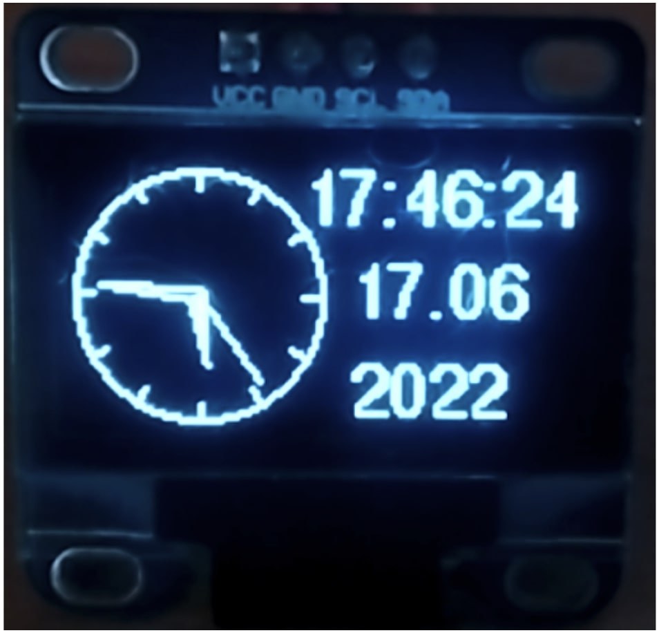
Now try to click the button S1. You should see the rectangle around the seconds value. If you now touch the touch button TS1 you can see that the seconds begin to increment. When the value is correct, just release the touch sensor and click the button S1 once again to switch to the next value. When you set all the parameters (the year is the last, as you remember) the next click on the S1 will remove all frames and restart the clock.
And that’s it. In this tutorial we have familiarized ourselves with the RTC module which is quite simple to work with. Also we have used more methods of the Adafruit GFX library and made a simple GUI interface.
As homework, try to make your own clock interface: play with fonts, locations, leave only the analog or digital part, in short, use your imagination and UI designer talents to make the most beautiful clock you can.

Get the latest tools and tutorials, fresh from the toaster.


