Drive a 1602 Character LCD | Embedded C Programming - Part 18
Published
Hi again! In this tutorial we will not discover any new MCU modules. Instead we will learn how to use the 1602 character LCD with the HD44780 driver. If you read the PIC10F200 tutorials, you should already be familiar with it. But that time I talked about it superficially, and now I will tell you about it in more detail.
The task for today is quite simple. As is customary in programming, we need to write the text “Hello world ☻” on the LCD. The “smiley” character should be generated manually and loaded into the Character Generator memory.
1602 LCD with the HD44780 Driver
There are several displays with the HD44780 driver, they can have different line numbers and position numbers (1x8, 2x8, 1x16, 2x16, 2x20, 4x20 etc.), also they can have different backlight colors (green, yellow, blue, etc.) or not have a backlight at all. The character’s color can be black or white. So, as you see, there is a diversity but all of them have the same interface and are controlled using the same commands. I have the display shown in Figure 1 which I bought a long time ago on Aliexpress.
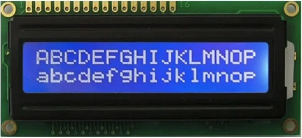
This LCD has the built-in character generator, so you don’t need to design your own characters (like we had to with the 7-segment indicator). We can just send the ‘A’ letter to the display, and it will be shown - fascinating, isn’t it? Also, the display has 16 empty cells in which you can load your own characters and then use them (I will talk about it later). The character generator of the LCDs from Aliexpress usually have a Chinese code page, so you can use the first 128 ASCII characters, which includes capital and small English letters, numbers, and punctuation signs which is quite good!
Let’s now see which signals this display has (Figure 2).
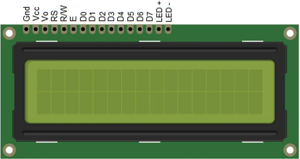
GND and VCC pins are the power supply of the display. Normally it is 5V but also can be 3.3V so be careful when buying an LCD.
The Vo pin is used to set the contrast of the LCD. Usually a potentiometer of 10-47 kOhm is connected to it.
RS is the data/command input. When this pin is low, the incoming data is considered as a command, and when it’s high, it is considered a character to display.
RW is the read/write input. When it is low, the data goes from the microcontroller to the LCD, and when it is high, the data goes the reverse direction. As we don’t expect any data from the LCD, we can connect this pin directly to ground.
E is the clock input. The data is read on the falling edge at this pin.
D0-D7 are the data inputs of the 8-bit parallel interface. The HD44780 driver also supports the 4-bit parallel interface. In this case, pins D0-D3 remain unused, and the bytes are transmitted by nibbles: higher one first, lower one second.
LED+ and LED- are the backlight power inputs. The supply voltage is also 5V, but a series resistor of 22-47 ohms is required.
As for the commands that the HD44780 uses, we didn’t consider them previously but now we will consider them in detail. I will base my explanations on the data sheet of the HD44780 driver, so you also can refer to it for full information. Let me present to table 6 from the data sheet (Figure 3) where all the LCD commands are described.
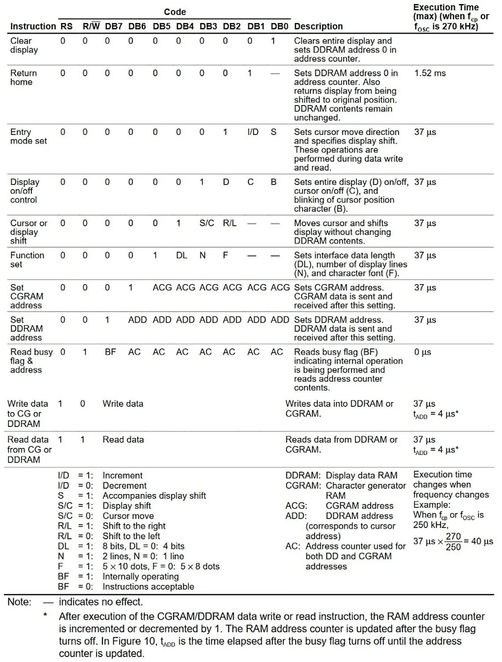
As you can see in Figure 3, the LCD has quite few commands, and each of them has at least one “1” in the data bits. Let me briefly run over all commands.
- “Clear display” command (0x01) seems to be quite clear (pun definitely intended): it clears the display content and sets the DDRAM counter to 0, so after this, the next character will be printed in the first position of the first line.
- “Return home” command (0x02) also clears the DDRAM counter to 0 but unlike the previous command, it doesn’t clear its content. Also if the shift was enabled for the display, the view returns to the initial position.
- “Entry mode set” command (0x04) has two parameters:
- I/D (bit #1) allows us to increment (if it is 1) or decrement (if it is 0) the DDRAM address which actually means if the text will be written left to right or right to left. For English text we need to set this parameter to 1 to write left to right.
- S (bit #0) allows us to shift the display leaving the cursor at the same position, when set to 1. The direction of the shift is set by the bit “S/C” of the command “Cursor or display shift”. When this bit is 0, no display shift occurs.
- “Display on/off control” command (0x08) has three parameters:
- D (bit #2) turns the display on when set to 1, and turns it off otherwise. The content of the DDRAM remains unchanged. So this bit just turns off the image, which can be restored instantly by setting it to 1.
- C (bit #1) enables (when it is 1) or disables (when it is 0) the cursor. The cursor is displayed in the 8’th line of the character (all characters have the size 5x7 pixels but the character place is 5x8 pixels, we will consider this later).
- B (bit #0) enables (when it is 1) or disables (when it is 0) the blinking of the overall position at the cursor. The blinking and the cursor can be enabled independently from each other, so you can select either any of them, or both, or none.
- “Cursor or display shift” command (0x10) has two parameters:
- S/C (bit #3) allows to shift the cursor by one position (the DDRAM counter also changes) if it is 0, or to shift the entire display (the counter remains the same) if it is 1. This option is useful to search the text in the display, or to implement the running line by the internal means of the display.
- R/L (bit #2) sets the direction of the shift: to the right when it is 1, or to the left when it is 0.
- “Function set” command (0x20) is one of the basic ones that needs to be implemented during the initialization process to allow the display to operate correctly. It has three parameters:
- DL (bit #4) sets the data bus width: 0 for 4 bits (in this case pins DB0-DB3 are not used, as I mentioned before), 1 for 8 bits (in this case all data pins are used).
- N (bit #3) sets the number of display lines: 0 for one line, and 1 for two lines.
- F (bit #2) sets the character font type: 0 for 5x8, 1 for 5x10. This parameter should be set according to the physical LCD type. The most widespread displays have the 5x8 characters, so we need to set this bit as 0.
- “Set CGRAM address” (0x40) sets the address of the character generator memory. This address has 6 bits width. I’ll explain this part in more detail later.
- “Set DDRAM address” (0x80) sets the address of the display data memory. This address has 7 bits width, and sets the position of the cursor at the LCD. Bit #6 sets the line number (0 – first line, 1 – second line), and bits #3-0 set the position within a line (0 to 15).
- “Read busy flag and address” commands allow reading the busy flag and address, as follows from its name. As we’re not going to use the reading option, I’ll let you delve into the details of this command on your own.
- “Write data to CG or DDRAM” command allows writing the data either to CGRAM or to DDRAM depending on the previous command: “Set CGRAM address” or “Set DDRAM address”, respectively.
- “Read data from CG or DDRAM” command allows reading from either CGRAM or DDRAM. As we’re not going to use the reading option, I’ll not consider this command any deeper either.
Now, let’s talk about the CGRAM. Let me copy table 5 from the datasheet (Figure 4) to illustrate how the generation of custom character happens.
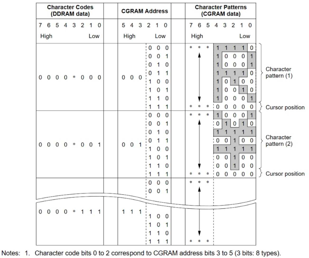
As I mentioned before there are sixteen DDRAM addresses in which you can locate the custom characters. But in fact, bit #3 in these addresses is not used (see Figure 4, column 1), so you can generate only eight custom characters.
As you can see from Figure 4 each character consists of eight lines. The lower three bits of the CGRAM address represent the number of a line within one character (top line first), and the upper three bits of the CGRAM address represent the number of the character. Also in the last column you can see that the upper three bits of the character generator are not used, and can be anything.
Let’s now try to generate the smiley face character and create the codes for it (Table 1).

So as you can see, we leave the upper three bits blank (which correspond to 0), and write the character only using the lower five bits. Also we leave the last line blank because this is the cursor position, so it’s better not to use it.
I think that’s all we need to know about the HD44780 driver to implement the given task, so let’s consider the schematic diagram of the device.
Schematics Diagram
Let’s look at the schematics diagram of this circuit (Figure 5).
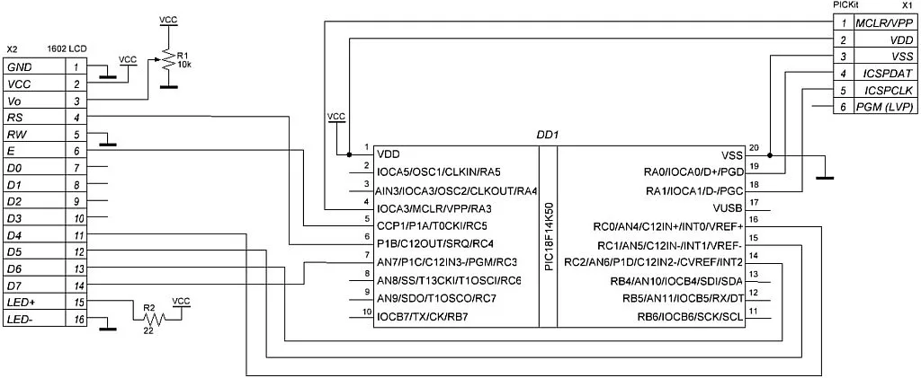
This schematic diagram consists of the PIC18F14K50 MCU (DD1), PICKit debugger (X1), and the 1602 LCD (X2) which is connected as described above. The Vo pin is connected to the 10-47 kOhm potentiometer R1. When you power up the device, you should rotate the handle of the potentiometer to make the rectangles of the LCD barely visible. Then the contrast level is set correctly. The LED+ pin is connected to VCC through the 22-47 Ohm resistor R2. The RS, E, D4, D5, D6, and D7 pins are connected to the MCU. The data pins D4-D7 are connected to the pins RC0-RC3, respectively. The RS input is connected to RC4, and E input is connected to RC5. The RW input of the LCD is connected to GND, as we will just write to the LCD. The D0-D3 inputs remain unused in the 4-bit interface.
Program Code Description
In this project we also will use the concept of distributing the code between different files like we did in tutorial 15. So we will create special files where we will write all the LCD-related code.
We need to create two new files: one “main.c…” and one “xc8_header.h…”, and call them both “lcd_1602” (see tutorial 15 for more details on how to do this).
Now let’s open the “lcd_1602.h” file and write the following text in it:
#include <xc.h> // include processor files - each processor file is guarded.


#define _XTAL_FREQ 32000000  //CPU clock frequency


void lcd_send (uint8_t value, uint8_t rs);  	//Send any data to the LCD
void lcd_command (uint8_t command);  //Send the command to the LCD
void lcd_data (uint8_t data);               	//Send the character to the LCD
void lcd_init (uint8_t cursor, uint8_t blink);  //Initialize the LCD
void lcd_write (char *s);                   	//Write the string at the LCD
void lcd_set_cursor (uint8_t x, uint8_t y); //Set cursor at the specified position
void lcd_create_char (uint8_t addr, uint8_t *data);//Create a custom character
In this file we define the _XTAL_FREQ macro as 32000000 because we will use the 32 MHz CPU frequency in the current project. Also pay attention, we define this macro in this file, not in “main.c”. This is because we will use it in several files, and it’s better to define it one time here rather than define it in every file.
The other lines of this file contain the function definitions that we will use for operating with the LCD.
The lcd_send function (line 5) allows sending the data byte to the LCD via a 4-bit interface. It has two parameters: value, which represents the byte that will be sent to the LCD, and rs which represents the state of the RS pin: 0 for low or 1 for high.
The lcd_command function (line 6) sends the command byte to the LCD, which is defined with the command parameter.
The lcd_data function (line 7) sends the character byte to the LCD, which is defined with the data parameter. This character will be sent either to CGRAM or to DDRAM.
The lcd_init function (line 8) initializes the LCD with the 4-bit interface. It has two parameters: cursor which shows (when it is 1) or hides (when it is 0) the cursor, and blink which enables (when it is 1) or disables (when it is 0) the blinking of the cursor position.
The lcd_write function (line 9) allows writing the string (parameter s) to the LCD.
The lcd_set_cursor function (line 10) sets the cursor at the position defined by the parameters x and y.
The lcd_create_char function (line 11) creates one character in the CGRAM memory at the address defined by the addr parameter. Parameter data is the array of 8 bytes that define the character.
Well, that’s all about the functions definitions, let’s now consider their description in the “lcd_1602.c” file:
#include <xc.h>
#include "lcd_1602.h"


void lcd_send (uint8_t value, uint8_t rs)//Send any data to LCD
{
	LATCbits.LC4 = rs;  	//Set RS pin (data/command)
	LATCbits.LC5 = 1;   	//Set E pin high to start the pulse
	LATC &= 0xF0;   //Clear the lower nibble of the LATC (set RC0-RC4 low)
	LATC|=(value & 0xF0) >> 4;//Send the upper nibble of the "value" to LCD
	__delay_us(1);      	//Delay needed by the driver
	LATCbits.LC5 = 0;   	//Set E pin low to finish the pulse
	__delay_us(1);      	//Delay needed by the driver
	LATCbits.LC5 = 1;   	//Set E pin high to start the pulse
	LATC &= 0xF0;   //Clear the lower nibble of the LATC (set RC0-RC4 low)
	LATC |= value & 0x0F;   //Send the lower nibble of the "value" to LCD
	__delay_us(1);      	//Delay needed by the driver
	LATCbits.LC5 = 0;   	//Set E pin low to finish the pulse
	__delay_us(40);     //Delay more than 37 us to implement the command
}


void lcd_command (uint8_t command)//Send command to LCD
{
	lcd_send(command, 0);   //Issue lcd_send function with RS = 0
}


void lcd_data (uint8_t data)//Send command to LCD
{
	lcd_send(data, 1);  	//Issue lcd_send function with RS = 1
}


void lcd_init (uint8_t cursor, uint8_t blink)  //Initialize LCD
{
	lcd_command(0x30);  	//Try to use 8-bit interface
	__delay_us(4200);   	//Delay for command implementation
	lcd_command(0x30);  	//Try 8-bit interface one more time
	lcd_command(0x28);  	//Set 4-bit interface, two lines
	lcd_command(0x08);  	//Turn off the display
	lcd_command(0x01);  //Clear the display and reset the address to 0
	__delay_us(4200);   	//Delay for command implementation
	lcd_command(0x06);  	//Cursor move direction from left to right
	lcd_command(0x0C | (cursor << 1) | blink); //Turn on display, set the cursor and blinking parameters
}


void lcd_write (char *s)	//Write the string at the LCD
{
	uint8_t i = 0;      	//Characters counter
	while (s[i])        	//While s[i] is not 0 (end of the string is C)
	{
    	     lcd_data(s[i]); 	//Send the character to LCD
    	     i ++;           	//Increment the characters counter
	}
}


void lcd_set_cursor (uint8_t x, uint8_t y) //Set cursor at the specified position
{
	if (y > 2)  	//If we try to set the line number more than 2
    	     y = 2;  	//Set the line #2
	if (x > 16) 	//If we try to set the position number more than 16
    	     x = 16; 	//Set the position #16
	lcd_command(0x80 | ((y - 1) << 6) | (x - 1)); //Set the cursor position at the LCD
}


void lcd_create_char (uint8_t addr, uint8_t *data) //Create a custom character
{
	if (addr > 7)  //If the address is higher than 7
    	     addr = 7;  //Then set address as 7
	lcd_command (0x40 | addr << 3); //Set the address of the CGRAM
	for (uint8_t i = 0; i < 8; i ++) //Loop to send all 8 bytes
	{
    	     lcd_data (data[i]); //Send data to LCD
	}
}
Let’s begin with the function lcd_send (lines 4-19). This is the most important function here and it implements the low-level communication between the MCU and LCD. To understand better how it works, let’s consider the part of the timing diagram from the figure 9 of the datasheet that corresponds to the writing cycle (Figure 6).
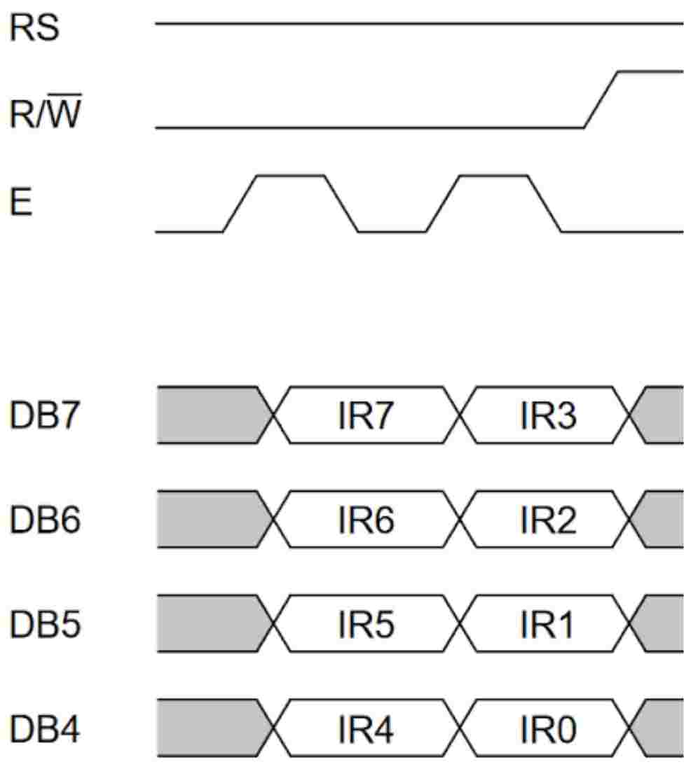
It’s not shown in Figure 6 but first you need to set the proper level at the RS pin (0 for command, 1 for data). This is what we do in line 6.
Then in line 7 we start the pulse at the E pin. As you remember (and as follows from Figure 6) the data is latched at the falling edge of the E pulse.
In line 8, we clear the lower 4 bits of the LATC register by implementing the bitwise AND operation between this register and the 0xF0 constant. This sets the pins RC0-RC3 to which the DB4-DB7 pins of the LCD are connected, low. Now we assign the upper nibble of the data to these pins, which we do in line 9. Let’s consider it in more detail.
LATC |= (value & 0xF0) >> 4
First, we need to extract the upper nibble of the value. To do this, we implement the bitwise AND operation between the value and the 0xF0, after that the lower four bits of the value will be 0. After that, we shift the received value 4 bits to the right, after that the upper nibble of the value will become the lower nibble. Now we can assign this value to the LATC register to set the pins RC0-RC3 according to the obtained value. To leave the RC4-RC7 pins unchanged we use not the direct assignment (“=”), but the bitwise OR operation (“|=”). Let’s consider these calculations using the table as we did before.
value | value & 0xF0 | (value&0xF0)>>4 | LATC before | LATC after |
0xABCDEFGH | 0xABCD0000 | 0x0000ABCD | 0xKLMN0000 | 0xKLMNABCD |
Here A, B, C, D, E, H, G, H, K, L, M, N are the random values of the bits.
In line 10, we perform the short delay of 1us which is needed by the LCD driver. Actually the minimal length of the E pulse is 230 ns according to the datasheet, but as we’re not going to display dynamic information, 1 us is fine.
In line 11, we set the RC5 pin low to end the first E pulse. At this moment the data at the DB4-DB7 pins is read by the LCD driver.
Now we implement another 1us delay (line 12) which corresponds to pause between the E pulses (Figure 6), and start the next E pulse by setting the RC5 pin high (line 13) to send the lower nibble of the data byte.
In line 14, we set the RC0-RC3 pins low the same as we did in line 8. Now we can assign the lower nibble of the value to these pins. This is simpler because we don’t need to perform any shifts now. Let’s consider line 15 in more detail.
LATC |= value & 0x0F
First we clear the upper four bits of the value by implementing the bitwise AND operation between the value and 0x0F. Then we assign the obtained value to the LATC register using the same bitwise OR operation as in line 9.
value | value & 0x0F | LATC before | LATC after |
0xABCDEFGH | 0x0000EFGH | 0xKLMN0000 | 0xKLMNEFGH |
Now pins RC0-RC3 levels correspond to the lower nibble of the value. Then we need to implement a 1us pause (line 16) and set the E pin low to latch the data (line 17).
After that, we consider that the 8 bits of the data byte are sent to the LCD. Finally, we implement the 40us delay to complete the operation. According to the HD44780 driver data sheet the time of execution of most commands is 37us. So 40us is quite enough. For the commands that need more execution time we will implement the additional delay beyond this function.
The lcd_command (lines 21-24) and lcd_data (lines 26-29) functions are very similar: they both consist of one line, in which the lcd_send function is invoked (lines 23 and 28). But in the lcd_command function the rs parameter is 0, and in the lcd_data function the rs parameter is 1. We couldn't use these functions and replace them with the lcd_send, but using them makes code more readable.
The lcd_init function (lines 31-42) initializes the LCD according to the routine suggested in the Figure 24 of the datasheet of the HD44780 driver but with slight changes.
First we need to try to set the 8-bit data interface by sending the “Function set” 0x30 command (Figure 3) (line 33). Then we need to implement a delay of more than 4.1ms, so we implement the 4200us delay (line 34). After that we try to set the 8-bit data interface one more time by sending the 0x30 command (line 35). The datasheet recommends trying to set the 8-bit interface a third time, but even without this it works well.
Then we set the data interface of 4 bits and two display lines by sending the “Function set” 0x28 command (line 36). Next, we need to turn off the display by sending the “Display on/off control” 0x08 command (line 37). After that we issue the “Clear display” 0x01 command (line 38) and wait for another 4200us (line 39) because implementation of this command requires more time.
Then we send the “Entry mode set” 0x06 command (line 40) which will increment the address after each character, and thus set the text direction from left to right.
Finally we send the “Display on/off control” command one more time (line 41) but this time we turn the display on. Also, we send the values cursor and blink at the corresponding bits (#1 and #0, respectively) to set the cursor parameters.
And that’s all about the initialization of the display. We can set more parameters if we’d like, such as auto-shifting of the display but we can do this separately if needed.
In lines 44-52 there is the lcd_write function. It displays the string ‘s’ in the LCD. The parameter s should be the c-type string with the terminating zero. This means that the string should end with the “0” character, which is the sign of the end of the line. This puts certain limitations, because we can’t display the character which is located at address 0 of the DDRAM but we can send it separately using the lcd_data function.
So, in line 46 we declare the variable i and assign its value as 0. This is the counter of the characters in the string. In line 47 we start the while loop which will be implemented while the current character is not 0. The content of the loop is quite simple. First, we send the current character to the LCD (line 49), and then we increment the character counter i (line 50).
In lines 54-61 there is the lcd_set_cursor function. In this function we consider that the first cursor position has the coordinates [1;1] but as the physical coordinates inside the display start with 0, we will need to subtract 1 from each parameter.
First, we need to limit the coordinates if we accidentally set them too big. We check if the y is bigger than 2 (line 56) and in this case set it as 2 (line 57). Then we check if the x is bigger than 16 (line 58) and in this case set it as 16 (line 59). Then we send the “Set DDRAM address” command to set the proper cursor position x and y (line 60).
The last function, lcd_create_char, is located in lines 63-72. In this function we also first check if the address is bigger than 7 (line 65) and set it as 7 in this case (line 66). This is needed because there are only eight available custom characters with addresses 0 to 7.
In line 67, we send the “Set CGRAM address” command, in which we shift the addr parameter 3 bits to the left. This is needed because the last 3 bits set the line address within one character (see Figure 4). After that, we implement the for loop (line 68) inside which we send the 8 bytes to the LCD which will form the required character (line 70).
And that are all functions that are required for operation with the LCD in the current and following projects. Please save these two files, we will copy-paste them to other projects as well.
Now, let’s consider the last file left, “main.c”.
#include <xc.h>         	//Include general header file
#include "lcd_1602.h"   	//Include 1602 LCD file


const uint8_t smile[8] = {0x0E, 0x1F, 0x15, 0x1F, 0x15, 0x1B, 0x0E, 0x00}; //Array to generate the smiley character


void main(void)         	//Main function of the program
{
	//GPIO configure
	TRISC = 0x00;       	//Configure RC port as outputs
	LATC = 0x00;        	//Set RC port low


	//Oscillator module configuration
	OSCCONbits.IRCF = 6;	//Set CPU frequency as 8 MHz
	OSCTUNEbits.SPLLEN = 1; //Enable PLL


	lcd_init(0, 0);     	//Initialize the LCD without cursor or blinking
	lcd_create_char(1, smile);//Create a smile character
	lcd_set_cursor(6, 1);   //Set cursor at the position 6,1
	lcd_write("Hello"); 	//Write "Hello"
	lcd_set_cursor(5, 2);   //Set cursor at the position 5,2
	lcd_write("world \1");  //Write "world"


while (1) {}        	//Main loop of the program
}
As you can see, the program is very short. This is because the majority of the code was written in previously described files. In line 2 we include the “lcd_1602.h” file to use the LCD-related functions.
In line 4 we define the constant array smile of 8 elements of uint8_t type. This array will be used to generate the smiley character. If you look attentively, you may notice that the elements of the array correspond to the values presented in table 1.
In lines 6-24 there is the main function of the program. In the initialization part we configure all pins of the port C as outputs (line 9) and set them low (line 10). Actually we need only pins RC0-RC5 but as nothing else is connected to the RC6, RC7 we can configure the whole port.
In lines 13-14 we set the CPU frequency as 32MHz (see tutorial 10 for more details).
In lines 16-21 there are functions related to the LCD. In line 16, we initialize the LCD without the cursor or blinking. In line 17, we create the new character at address 1 using the array smile. In line 18, we set the cursor at the sixth position of the first line, and then write the text “Hello” in it (line 19). In line 20, we set the cursor at the fifth position of the second line, and then write the text “world ☻” there (line 21). Pay attention to the expression “\1” in the text. The backslash symbol makes the next character in the string the special one. For example “\n” means the new line, “\r” means carriage return, “\”” means the quote sign, etc. If the number follows the backslash, this means that we want to print the character with the address defined by this number. So the expression “\1” means the character at the address 1, which is the smiley that we defined in line 17.
In line 23 there is the main loop of the program which is empty now because we don’t need to do anything as a cycle in our program.
And that’s all about the firmware. Now we can proceed to the practical work.
So assemble the device according to the schematics diagram (Figure 5), compile the program, and connect your PICkit to the PC. Configure the PICkit voltage according to your LCD type (5V or 3.3V) and run the program. You should see the text “Hello world ☻” on your LCD. If you don’t see the text even now, rotate the potentiometer handle to set the contrast, this should help. If you still don’t see anything then check the connections: there are a lot of wires in this device and it’s easy to mess up.
As homework, I suggest you experiment with the LCD parameters: cursor type, blinking, display shift, generation of several characters etc.

Get the latest tools and tutorials, fresh from the toaster.


