Introduction to MCUBoot using the Renesas RA Family Part 3 | Renesas RA - 12
Published
Using MCUboot in Direct XIP Mode
Hello again! In this part we consider the last (but not the least) MCUboot mode. In the first part we considered the Overwrite Only mode, in the second part we considered the Swap mode, and now the time has come to get familiar with the Direct XIP mode. As you remember, in this mode the user’s application can be executed both from the primary or the secondary slot depending on the specific settings which we will consider very soon.
Creation and Configuration of the Bootloader Application in Direct XIP Mode
Here we will use the same approach as in the previous part: we will not create a new project from scratch but import it from the one that we have created in the first portion of this MCUboot tutorial. I will repeat all the steps here once again, so you don’t need to refer to both parts to create this project.
Select the “File” in the main menu and then click on the line “Import..” (Fig. 1).

In the opened window select the “Rename & Import Existing C/C++ Project into Workspace” (Fig. 2).

Click the “Next >” button and see the next window (Fig. 3).

In the top field type the new project name. Let it be “mcuboot_direct_xip_no_signature”. Then click the “Browse…” button near the field “Select root directory” and select the “mcuboot_overwrite_with_signature” which we have created in the first part. Then in the “Projects” field you will see this project. Select it and click the “Finish” button.
Now, in the Project Explorer you can see the new “mcuboot_direct_xip_no_signature” project. If you open its files, you can see that it’s absolutely identical to the “mcuboot_overwrite_with_signature”. So this time we will not need to execute all the steps to reduce the bootloader application size and to change the code. The only thing we need to do here is to reconfigure the “MCUboot” stack. So open the “configuration.xml” file of the “mcuboot_direct_xip_no_signature” project, move to the “Stacks” tab and click on the “MCUboot” block to open its properties. Then change them according to Fig. 4.
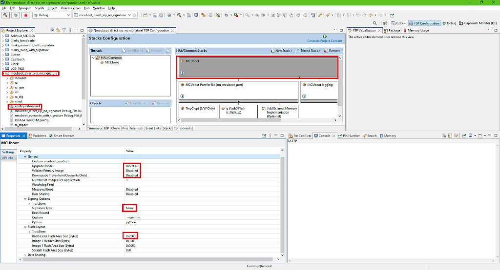
Here I highlighted with the red boxes the options that differ from the first project. So we need to change the “Upgrade Mode” to “Direct XIP” to run the MCUboot in the Direct XIP mode. Then we disable the downgrade prevention, as it is applicable only in the Overwrite mode.
Also this time let's disable the “Validate Primary Image” option to see what are the differences if we don’t use it. As we don’t validate the primary image, we need to change the “Signature Type” to “None”, as we don’t need to sign the application.
Unlike the previous part, we will use the “--confirm” custom signing option to achieve the primary image confirmation at compilation. For more information about this option and about the “image_ok” byte please refer to the second part of this tutorial.
Finally, we need to decrease the “Bootloader Flash Area Size (Bytes)” from 0x3800 to 0x2000, as this application requires less memory due to absence of the signing part.
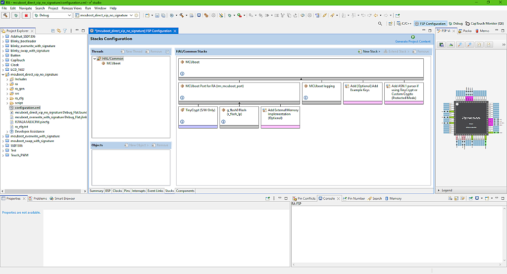
Also, in the “HAL/Common Stack” window we need to consequently select the blocks “MCUboot Example Keys (NOT FOR PRODUCTION)” and “MCUboot ASN.1 parser” and then click at the “Remove” button to delete them (Fig. 5).

These two blocks are also used for signing the application, so we don’t need them anymore. After that your MCUboot stack should look like in Fig. 6.
Now we can click the “Generate Project Content” button, and then build the project. There should not be any errors. The code size is 7360 bytes (Fig. 7), which in the hexadecimal format is 0x1CC0, that’s why we set the Bootloader Flash Area Size as 0x2000 this time.

This time we don’t need to configure the Python environment, as it has been done in the first part, and as I mentioned, it needs to be done just once. So far that’s actually all we need to do with the bootloader application, as you can see, if we import the existing project, it takes much less time to configure it. If you want to create this project from scratch, you need to go through all the steps described in the first part, the only difference is the “MCUboot” block configuration (Fig. 4), everything else is the same.
Let’s now create the user’s application based on the previous one.
Creation and Configuration of the User’s Application in Swap Mode
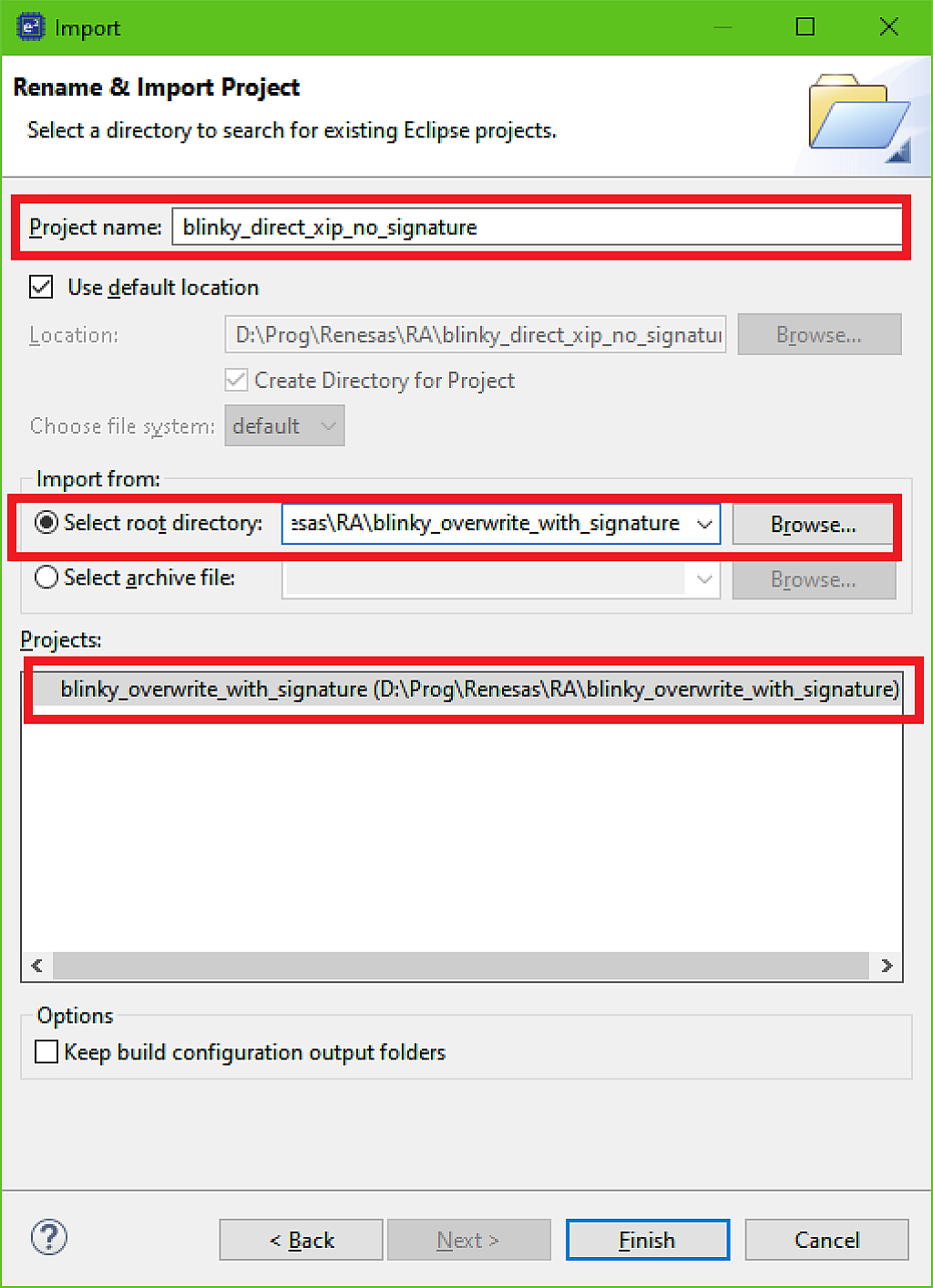
Let’s rename and import the “blinky_overwrite_with_signature” project from the previous part in the same way as we did with the bootloader application (Fig. 1, 2) and call it “blinky_direct_xip_no_signature” (Fig. 8).
Even though this application just makes an LED blink, we will need to change more things in it. First we need to right click on the “blinky_direct_xip_no_signature” project and open its properties. Then in the “C/C++ Build” list in the left parts select the “Build Variables” line, then click on the “BootloaderDataFile” variable, and click the “Edit…” button (Fig. 9).

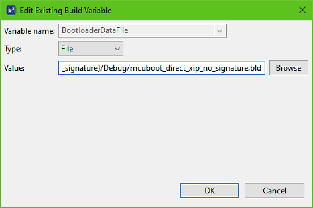
As you remember, this variable consists of the path to the bootloader’s “.bld” file which is used for signing the application.
So we need to replace the “mcuboot_overwrite_with_signature” text in the path with the “mcuboot_direct_xip_no_signature” to link this user’s application with the new bootloader application. Don’t forget to replace it twice - in the project name and in the “.bld” file name (Fig. 10).
Then select the “Environment” in the left list. Here we need to edit the Environment variables. Click on the “MCUBOOT_IMAGE_SIGNING_KEY” and then click on the “Delete” button (Fig. 11) as we don’t use signing the application this time.
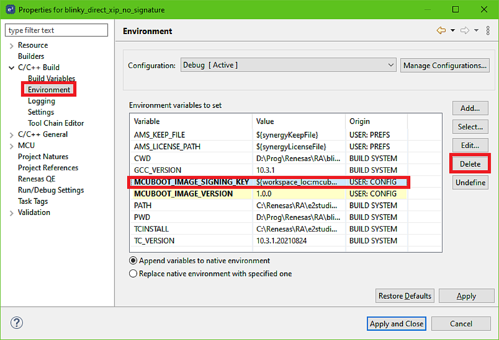
Then check the “MCUBOOT_IMAGE_VERSION” variable. Make sure that its value is “1.0.0” like in Fig. 11. If it’s different then edit it.
Now we need to do the thing that is specific to only this mode. We need to define in which slot the image will be located: in the primary or in the secondary. To do this there is a special linker macro called “XIP_SECONDARY_SLOT_IMAGE”. If it’s defined as 0 then this image should be downloaded into the primary slot, and if it’s 1 then the image should be located in the secondary slot. Let’s now see how to define it.
We need to select the line “Settings” in the left list, then in the central window select the “Miscellaneous” line of the “GNU Arm Cross C Linker” list. Then click on the “Add…” button
at the “Linker flags (-Xlinker [option])” field. And in the opened window type “--defsym=XIP_SECONDARY_SLOT_IMAGE=0” (Fig. 12).
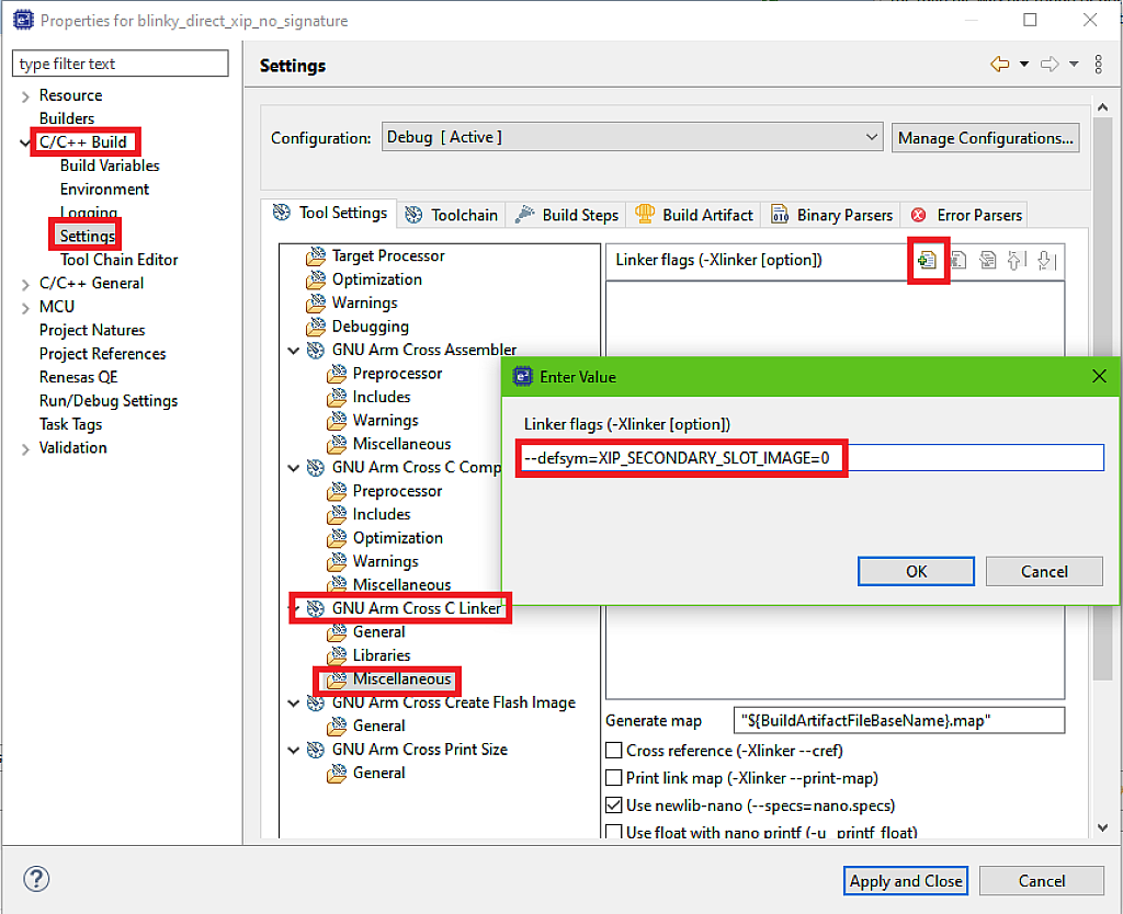
Then click “OK” to return to the previous window. Now you can click the “Apply and Close” button to return to the main window of the IDE.
Now we can build the project. If you did everything correctly, there will not be any errors. Please make sure that there is the “blinky_direct_xip_no_signature.bin.signed” file in the “Debug” folder (Fig. 13).

Now, as both applications are ready, let’s run the project.
Downloading the Initial User’s Application
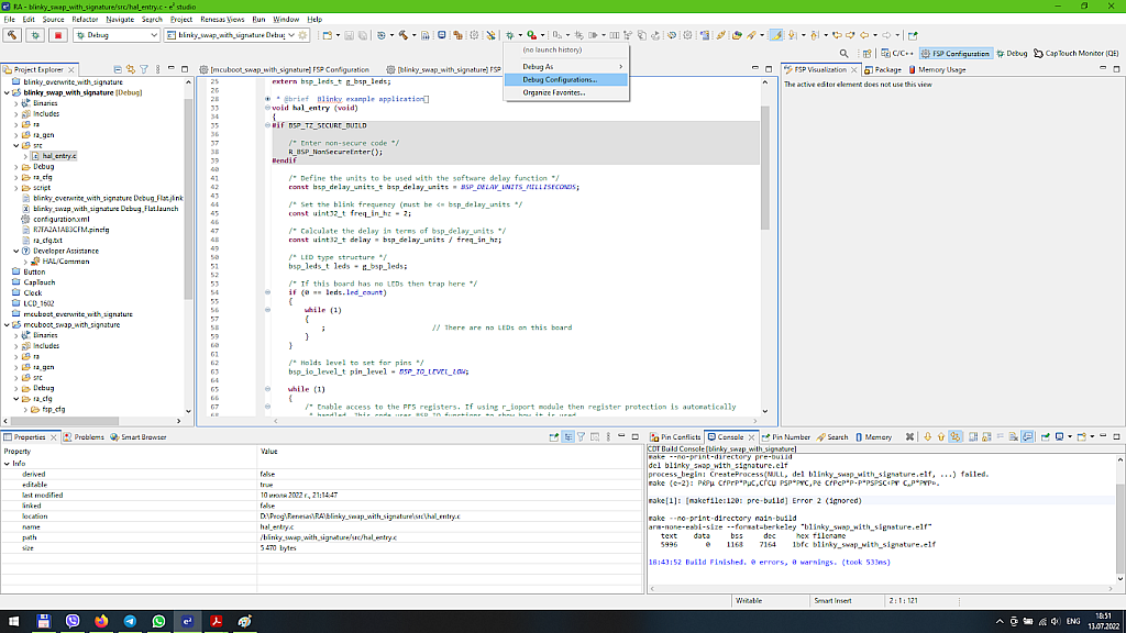
The same as the previous time, open the “Debug Configurations…” (Fig. 14).
In the opened window make sure that you configure the “blinky_direct_xip_no_signature_Debug_Flat” in the left list then switch to the “Startup” tab, click on the second image and then change it by clicking the “Edit…” button (Fig. 15).

In the opened window, replace the “mcuboot_overwrite_with_signature” with the “mcuboot_direct_xip_no_signature” both in project name and file name (Fig. 16).

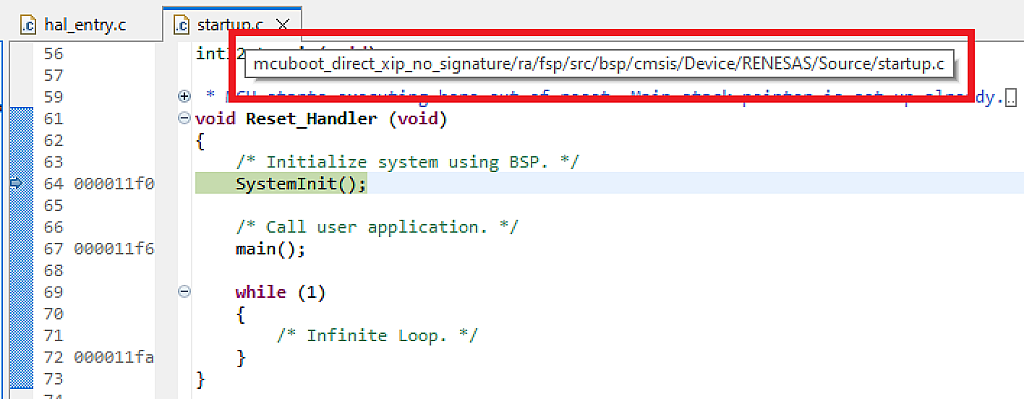
Click “OK” to return to the previous window, and then click “Debug” there. Make sure that we stopped at the Reset_Handler of the “mcuboot_direct_xip_no_signature” project (Fig. 17).
Now, the same as the previous time, click at the “Load Ancillary File” button and select the “${workspace_loc:\blinky_direct_xip_no_signature\Debug\blinky_direct_xip_no_signature.bin.signed}” file. Also, please change the address to 0x2000 because as you remember (see Fig. 4), this bootloader application has the size 0x2000 bytes (Fig. 18).
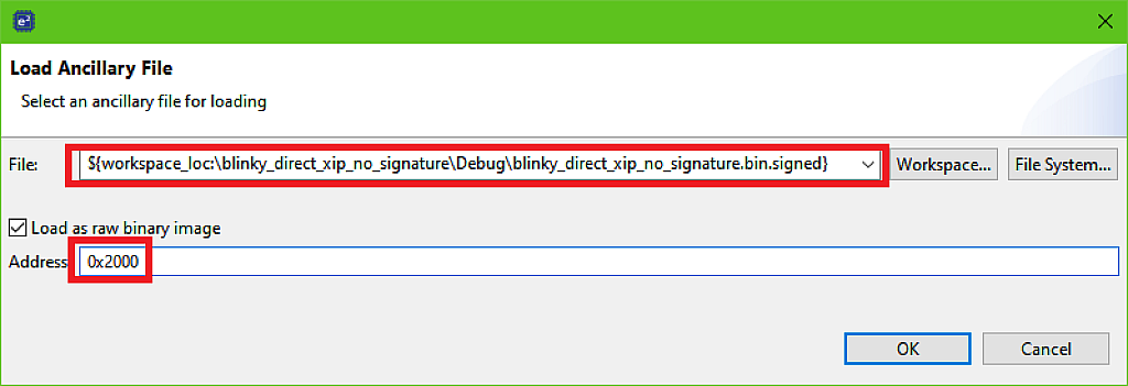
Click “OK” to download the user’s application to the primary slot. Then press the “Resume” button twice to run the bootloader. If you did everything correctly, you should see the slow flashing of the LED.
Let’s now see the memory regions of the primary and secondary slots. Please note that this time they start at addresses 0x2000 and 0x7000, respectively (Fig. 19, 20).
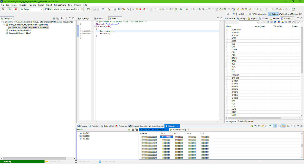
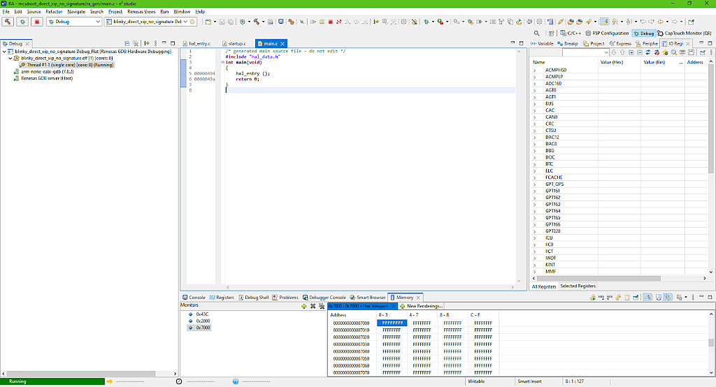
So in the primary slot there is the correct application, and the secondary slot is blank because, in the Direct XIP mode, if the MCUboot doesn’t find the valid image in a slot, it erases the entire slot and doesn’t check it the next time.
This is the initial program setup, let’s now change the user’s application and download it into the secondary slot.
Let’s open the “hal_entry.c” file of the “blinky_direct_xip_no_signature” project and change the value of the freq_in_hz variable from 2 to 8 in line 48.
Then we need to open the properties of the “blinky_direct_xip_no_signature” project and change the value of the “XIP_SECONDARY_SLOT_IMAGE” macro to 1 to let the bootloader know that this image should be located at the secondary slot. To do this, double click on the line “--defsym=XIP_SECONDARY_SLOT_IMAGE=0” and replace “0” with “1” (Fig. 22).
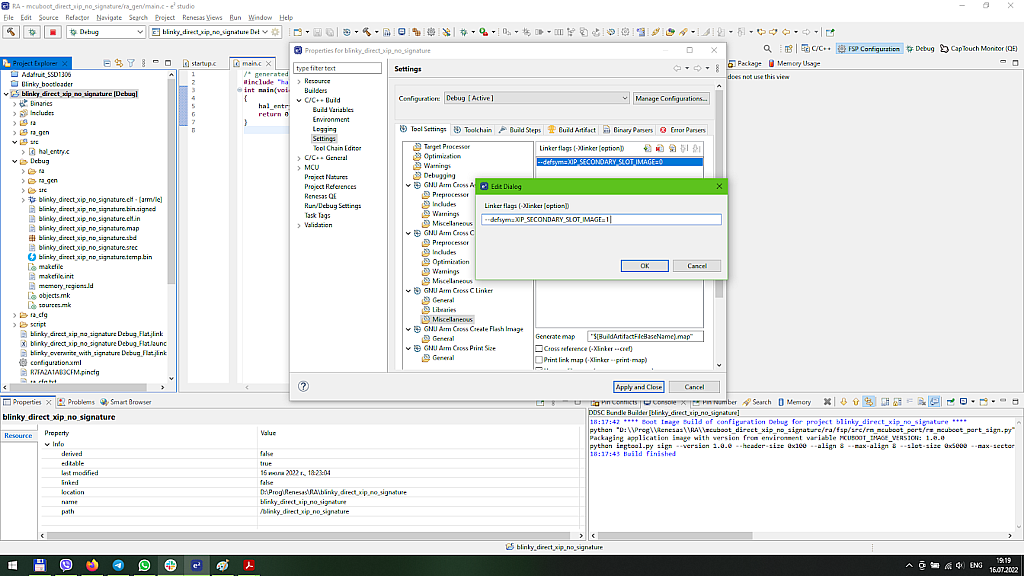
Then click “OK” to save changes and return to the properties window.
There is one more thing we need to change here. Let’s select the “Environment” line in the left list and update the value of the “MCUBOOT_IMAGE_VERSION” to “1.0.1” (Fig. 23).

Now you can click “Apply and Close” to return to the main IDE window.
A Deeper Conceptual Dive into the Direct XIP Mode
I think the time has come to explain in more detail how the MCUboot operates in the Direct XIP mode. First, it checks if there are images in both slots. Then it compares the version numbers of the images and selects the one with the highest version number (that’s why we had to upgrade it). Then it checks the validity of this image, and if it’s OK, executes it. If the image is not valid, MCUboot erases this slot to prevent its checking the next time, and checks the validity of the image in the other slot. If it’s valid, then the bootloader executes it. To be frank, I’m not sure what will happen if it isn’t valid, I think it will either erase the image or it just won’t run it.
Now let’s build the project and open the “Debug Configurations…” once again. Once the bootloader and the primary application are already in the flash memory there is no need to download them every time. Switch to the “Startup” tab and for the bootloader image also select “Symbols only”. Also, you can uncheck the checkbox “Set breakpoint at: main”, this will prevent needing to double click the “Resume” button (Fig. 24).

Now you can click the “Debug” button and see that we are still at the same Reset_Handler of the bootloader. Click on the “Load Ancillary File” button and load the secondary application to its slot (address 0x7000, Fig. 25).

Click the “OK” button to download the image to the secondary slot.
Let’s now click the “Resume” button to let the bootloader do its business. After a few moments, you should see that the LED is flashing fast. This means that the new image was checked, validated, and is now running.
If you reset the board, you will see that the LED still blinks fast. Let’s now open the properties of the “blinky_direct_xip_no_signature” project and change the “MCUBOOT_IMAGE_VERSION” to 0.9.0 (Fig. 26).

We will not change anything else in this application, and just build and debug it. As the version of the image in the secondary slot is lower than the version of the image in the primary slot, the bootloader should select the later one. Let’s check if it’s so.
After starting the debugging session, download the image to the secondary slot the same as in Fig. 25 and click “Resume” to run the bootloader. This time the LED will blink slowly which confirms that the bootloader works as desired.
Now a few words about the rollback function in the direct XIP mode. It works almost the same as in the Swap mode (see the previous portion of the tutorial). To enable it, you should change the Custom Signing Option from “--confirm” to “--pad”, and add the “MCUboot Image Utilities” stack to the user’s application. Then if you add the boot_set_confirmed function to the code, the new image will be confirmed, and after the reset it will be loaded as usual. But if you add the boot_set_pending function, the image will not be confirmed, and after the reset it will be considered by the bootloader as invalid, and thus erased. So the image in the other slot will run even though it has the lower version.
And that’s about everything for the operation of MCUboot in the Direct XIP mode. As you see, it’s quite simple in comparison to the Swap or even Overwrite mode. You just need to take care about the “XIP_SECONDARY_SLOT_IMAGE” macro value to download the image into the correct slot.
In the next part we will consider how to download the firmware file into the flash memory of the MCU using its internal built-in bootloader.
As homework, try to change the code of the bootloader and the user’s application to perform the code confirmation at the runtime by changing the custom signing option from “--confirm” to “--pad” the same as we did in the Swap mode. Check how the rollback function works in this case.

Get the latest tools and tutorials, fresh from the toaster.


