Control WS2812B LEDs Using MCC | Embedded C Programming - Part 11
Published
Hi there! We continue operating with the WS2812B LEDs but this time we will use the MCC. Actually, the program will be very similar to the previous one, the only new thing we will do with the MCC is configure the oscillator module.
If you have read the previous tutorial, you can skip the theory part as it will be the same and move to the MCC module configuration. Otherwise keep reading to get more information about the WS2812B LEDs.
WS2812B LEDs Introduction
So, let’s consider what the WS2812B LEDs are. The LED itself looks like a typical 5050 package SMD LED (Figure 1).

But inside it there is a special circuit which allows us to control the LED color and brightness with a one-wire digital protocol. Moreover, these LEDs can be connected in a daisy-chain, which makes it possible to control a line of these LEDs with only one MCU pin.
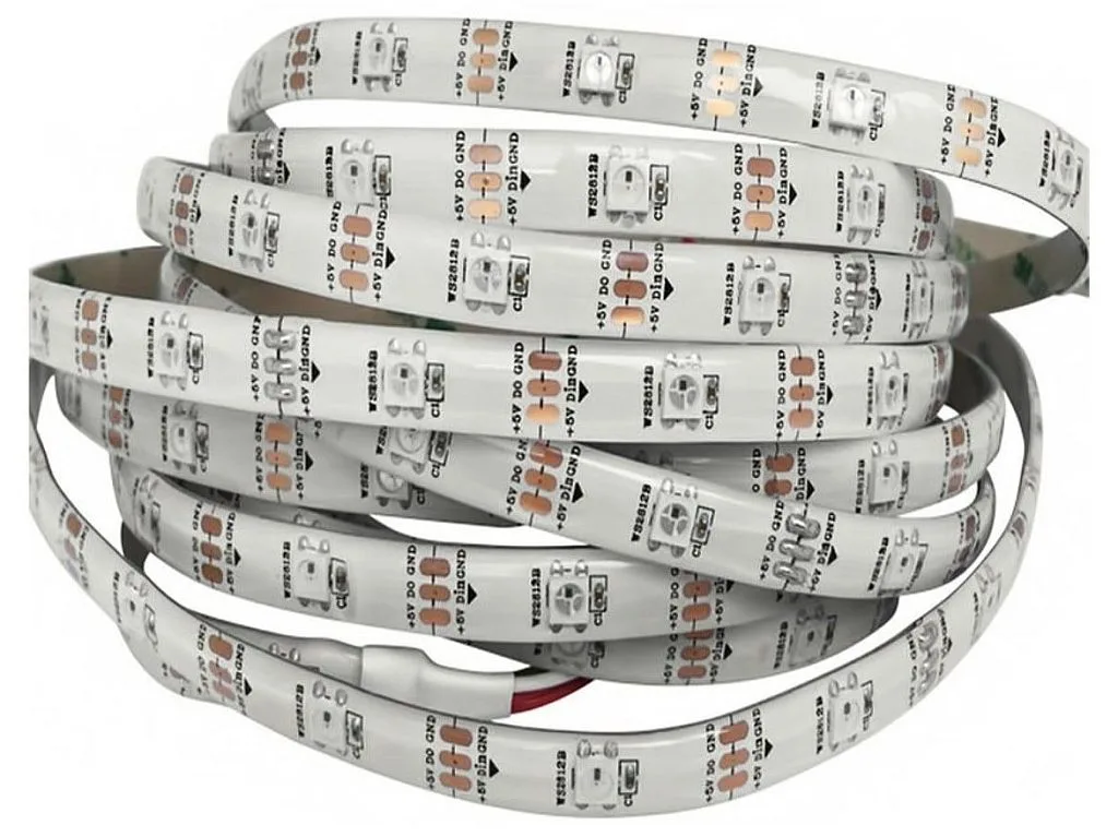
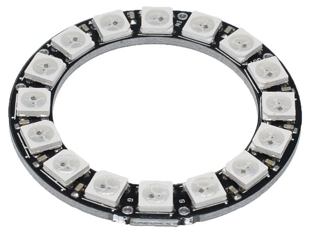
Thus these LEDs often are available not as standalone devices but as lines (Figure 2), strips (Figure 3), rings (Figure 4), matrices (Figure 5) etc.


And all these circuits are controlled with just one MCU pin!
Let’s now consider the digital protocol and the LEDs connection. I will take the image from the datasheet of the WS2812B LED (Figure 6).

So this protocol is quite simple: to transmit “0” we send the pulse with the width of T0H, and then pause (or go low) the width of T0L. The same with sending “1”. To send the reset state, we need to issue the negative pulse of the Treset width. “Quite simple” - you may say. Yes, that’s true. But let’s look at the timings provided in the same datasheet (Table 1).
Table 1 - WS2812B Timings
Data Transfer Time (TH+TL=1.25µs±600ns)
| T0H | 0 code, high voltage time | 0.4us | ±150ns |
| T1H | 1 code, high voltage time | 0.8us | ±150ns |
| T0L | 0 code, low voltage time | 0.85us | ±150ns |
| T1L | 1 code, low voltage time | 0.45us | ±150ns |
| RES | low voltage time | Above 50µs |
As you see, the pulse widths are very short: 0.4 - 0.85 us (I don’t take into account the Reset pulse, it’s quite long, and there is no problem with it). So the discreteness of the timing cannot be more than 0.05 us which requires the frequency of 1 / 0.05 us = 20 MHz. And currently the PIC18F14K50 has only 1 MHz. Moreover, each instruction in the PIC MCU is implemented during 4 ticks of the CPU clock, so the real operating frequency is just 1 MHz / 4 = 250 kHz. And this is a big problem we need to solve somehow. But let’s put it aside for a while and return to the WS2812B LED control.
To set the color of the LED we need to send the reset pulse followed by a packet of 24 bits. These bits represent the RGB components of the LED color (Figure 7).

So, as you see, the upper 8 bits set the green component, the middle 8 bits set the red component, and the lower 8 bits set the blue component.
As follows from Figure 6 the LEDs can be cascaded by connecting the DOUT pin of the previous LED with the DIN pin of the next LED. To send the data to several LEDs connected in a chain you need to do the following:
- Issue the reset pulse.
- Send a packet of 24 bits to set the color of the first LED.
- Without issuing the next reset pulse send another packet of 24 bits. They will be transparently transmitted to the next LED and set its color.
- Repeat step 3 as many times as how many LEDs you have.
I think this information is enough to start working with the WS2812B LEDs, so we can now formulate the task for the current tutorial: control a line of the WS2812B LEDs using the PIC18F14K50 MCU (the form and number of LEDs depends on what you have: line, ring, strip, matrix or other shape). As you see, the task is not surprising, so let’s try to implement it.
Schematics Diagram
First, we need to consider the schematics diagram that implements the given task (Figure 8).
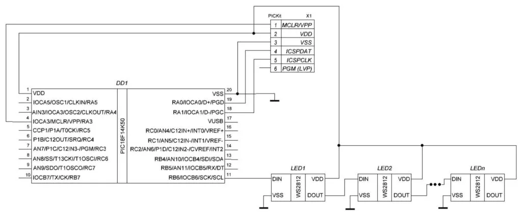
In this schematics you see the same MCU PIC18F14K50 (DD1) and the programmer PICKit (X1) as well as the set of WS2812B LEDs (LED1, LED2, … LEDn). I skipped the capacitors which are required for normal operation of the LEDs. They should be connected between the VSS and VDD pins of each LED and have a value of 0.1uF. Frankly, I expect you to use some ready board or strip, on which these capacitors are already installed. By the way, even though I didn’t mention this before, it’s a good idea to connect a couple of capacitors between the VDD and VSS pins of the MCU as well, with values of 0.1 uF and 10 uF, this will increase the stability of the MCU operation.
Personally, I have a simple LED strip shown in Figure 3 which consists of just 8 LEDs, so I will use it. But the program code will be expandable to any number of LEDs.
Oscillator Module
Before we start considering the program code, we need to solve the timings issue. To figure out how to do this, we need to get acquainted with the oscillator module. It provides the clocking of the CPU and the MCU peripheral modules. I already mentioned it in tutorial 2, when I talked about the configuration bits. And I said that by default the CPU is clocked with an external RC oscillator, and we need to switch it to the internal oscillator.
Actually there are several clock sources, both external and internal, but this time we will consider in detail only the internal high-frequency oscillator. We already have it enabled by setting the configuration bits as described in tutorial 2. Now we just need to configure it.
So the high-speed internal oscillator (also called HFINTOSC in the datasheet) runs on different frequencies in a range of 31 kHz to 16 MHz. So we can overclock the CPU up to 16 MHz using the HFINTOSC module, but as I mentioned in the previous chapter, the real instruction implementation speed will be just 16 / 4 = 4 MHz which is still not enough. So is there any other way to overclock the CPU even more?
The answer is an affirmative. And to do this we need to use the so-called 4x Phase Lock Loop (PLL) Frequency Multiplier module. As follows from its name, it multiplies the input frequency 4 times. And here one could say “Wow! So we can multiply 16 MHz by 4 and get 64 MHz frequency!” Unfortunately, no. The PLL circuit is more adapted to work with an external primary oscillator, and it can multiply its frequency in the range of 4 MHz to 12 MHz, so the maximum CPU frequency can be 12 x 4 = 48 MHz if using an external oscillator. For the HFINTOSC we can only select the 8 MHz frequency to work with the PLL. So the maximum achievable frequency from the internal oscillator with the enabled PLL is 8 x 4 = 32 MHz. So we will use it, as we can’t get more for now.
For now that’s all we need to know about the oscillator module to implement the current task, so we can proceed to the project creation and configuration.
Configuration of the Project using MCC
I hope you already remember how to create the new project and run the MCC module. If not, please refer to this Introduction to the MPLAB Code Configurator (MCC) tutorial.
This time we will need to configure just the Pin Module and System Module. As we will use only one MCU pin RB6 to control the LED line (Figure 8), the connection table will be quite short (Figure 9).
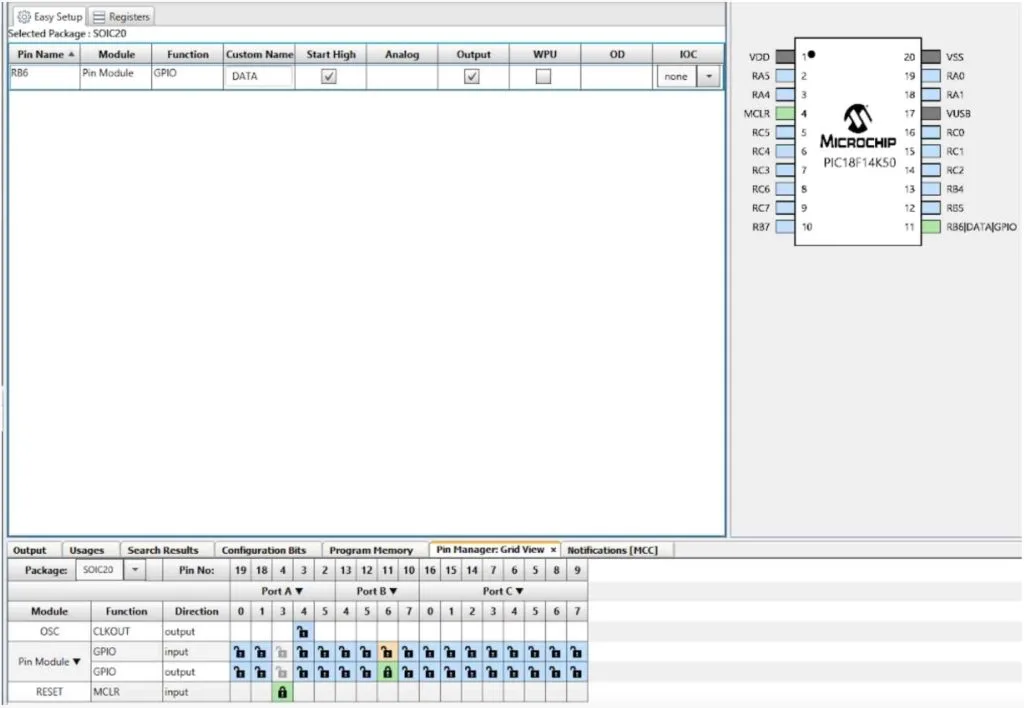
We configure the RB6 pin as output, also we need to set the check “Start high” to start the LED bus high. Also, let’s give it the custom name DATA.
Then we need to switch to the System Module tab and change the parameters according to Figure 10.
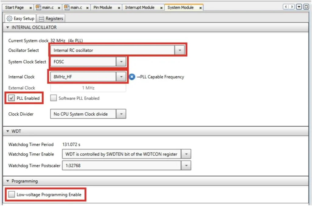
We leave the oscillator as “Internal RC oscillator”, and the system clock as “FOSC”. Then we change the internal clock to “8MHz_HF” to set the oscillator frequency as 8 MHz. The MCC will hint to us that this frequency is “PLL Capable Frequency”. Below, we need to enable the PLL. There are two options: “PLL Enabled” and “Software PLL Enabled”. In reality, they both do the same thing - enable the PLL. But in the first case it’s done by setting the corresponding configuration bit, and thus it can’t be turned off by the software. In the second case the PLL is enabled by setting the special bit in a regular register which can be changed any moment by the software. For us, there is no difference either way, as we don’t plan on changing the PLL in the firmware. So you can check either option.
And finally don’t forget to disable the Low-voltage programming. And that’s all the settings that need to be done with the MCC. Now we can click the “Generate” button and switch to the “main.c” file.
Program Code Description
#include "mcc_generated_files/mcc.h"


#define LED_NUM	8    	//Number of LEDs


uint32_t color;         	//Current color
uint8_t overflow;       	//Color value overflow flag


void ws2812_color (uint32_t color)  //Set the color of the LED
{
     for (uint8_t i = 0; i < 24; i ++)   //The loop to set 24 bits (one full LED)
     {
    	DATA_SetHigh(); 	//Set the DATA pin high to start the pulse
    	if (color & 0x800000) //If the MSB of the color is 1
    	{
        	     __nop();    	//Then perform a delay for 3 commands
        	     __nop();
        	     __nop();
    	}
    	DATA_SetLow();  	//Set the DATA pin low to finish the pulse
    	color <<= 1;    	//Shift the color value
     }
}


void ws2812_reset (void)	//Reset the LED
{
	DATA_SetLow();      	//Set the DATA pin low to start the reset pulse
	__delay_us(50);     	//Perform the delay of 50us
}


void main(void)
{
     SYSTEM_Initialize();

     color = 0x000FFF;   	//Set the initial color

     while(1)
     {
    	ws2812_reset(); 	//Reset the LED interface
    	for (uint8_t i = 0; i < LED_NUM; i ++)//Loop to send to all LEDs
        	ws2812_color(color << i);   //Send the specific color to each LED
    	if (color & 0x800000)   //If the MSB of the color is 1
        	overflow = 1;   	//Then set the overflow flag as 1
    	else                	//Otherwise
        	overflow = 0;   	//Set the overflow flag as 0
    	color <<= 1;        	//Shift the color at the 1 bit to the left
    	color += overflow;  	//And add the overflow value as an LSB
    	__delay_ms(100);    	//Perform the delay between the color change
     }
}
In line 3 we define the macro LED_NUM which defines the number of LEDs that are connected in series to pin RB6. As I mentioned before, I have a simple line of 8 LEDs, so I defined LED_NUM as 8.
Next, we define two variables: color of type uint32_t (line 5) to set the LED color, and overflow of type uint8_t (line 6) which will be used in shifting the LED colors.
In lines 8-22, there is a function ws2812_color which accepts the parameter color and sends 24 bits to the LEDs. This function has some tricks to decrease the execution time to meet the timings requirements.
In line 10, we start the “for” loop from 0 to 24 to send 24 bits to the LED. At the beginning of the loop we set the DATA pin high (line 12) to start the pulse (Figure 6). Then we check the MSB of the color parameter (line 13). Let’s consider this line in more detail.
The “&” sign means the bitwise AND operation. The constant 0x800000 in binary representation is 0b100000000000000000000000, so only its most significant bit is “1”. When we implement the “&” operation between the color variable and 0x800000, the result will be true only if the MSB of the color variable is “1”, in all other cases it will be 0.
So if MSB of the color is “1” we need to implement the 0.8 us delay (T1H time) and if it is “0” the delay should be 0.4 us (T0H time). As we remember the CPU frequency is 32 MHz, and the instruction execution frequency is 32 / 4 = 8 MHz which means that the instruction execution time is 1 / 8 MHz = 0.125 us. The trick is that the time of execution of lines 12-13 is 0.5us. So we don’t need any extra delay to send the “0” value. And the 0.5 us value fits into the 0.4 ± 0.15 us range, so for “0” we have success! To transmit “1” we need to add at least 0.3 us which we do by calling the three assembly-based functions __nop() (lines 15-17). In this case the overall delay will be 0.5 + 0.125 * 3 = 0.875us which also fits into the range of 0.8 ± 0.15 us. In fact, the real pulse width is 0.75us (If you are interested why, you can refer to the previous tutorial) which also fits into the desired range. Now we’re good with the positive pulse, and can finish it by setting the DATA pin low (line 19).
In line 20, we shift the color value one bit to the left (if you don’t know, the “<<” operator means shift to the left, and “>>” operator means shift to the right by the specified number of bits). So at the next loop iteration we will check the next bit of the color parameter and send the output pulse according to it.
The delay between the pulses is the same for “0” and “1” and is formed with the lines 19, 20, and 10. It is 1.375 us. This value is much bigger than the T0L and T1L from Table 1. But it turns out that the LED’s logic can accept this value as well. Actually any delay lower than 20us is fine. A longer delay than 20us will be considered as a “reset” pulse.
The transmission of one 24-bit packet taken by the logic analyzer is shown in Figure 11, and the timings for 0 and 1 are shown in Figure 12 and Figure 13, respectively.


OK, we have finally finished with the ws2812_color function, and now can consider the next one, called ws2812_reset which is located in lines 24-28. It’s quite simple and will not take a lot of time. First, we set the DATA pin low to start the reset pulse (line 26), and then perform the delay of 50 us by issuing the function __delay_us (line 27). We don’t return the DATA line high here because this will distort the first pulse of the data packet, and if the delay is longer than 50 us, it will not cause any problems.
These are all functions that are required to operate with the WS2812B LED. Now we can proceed to the main function of the program (lines 30-49). As usual, we first need to initialize the peripheral modules of the MCU by calling the SYSTEM_Initialize function (line 32).
In line 34, we assign the 0x000FFF value of the color variable. According to Figure 7 this value corresponds to the blue color with a slight red hue.
That’s all the initialization required, so we can proceed to the main loop of the program (lines 36-48). Here I implemented a kind of running line where the color gradually changes from one LED to another.
First, we issue the reset state at the LED interface (line 38). Then we send the packets to each available LED with the “for” loop (line 39). In line 40 we shift the color to the right to the number of bits corresponding to the i variable value. This will make an effect of the gradient.
In lines 41-44 we save the MSB of the color variable in the overflow variable. So if the MSB of the color is “1” (line 41) we assign “1” to the overflow (line 42), otherwise (line 43) we assign “0” to it (line 44). Then in line 45 we shift the color variable at the one bit to the left, and finally add the overflow value to the color (line 46). The meaning of lines 41-46 is the following. We want to shift the color value so that in the next loop iteration each LED will have a new color. But this shift operation isn’t rotated, so the MSB of the shifted value doesn’t become its LSB and is lost forever. To prevent this we need to use the special variable and manually move the MSB to LSB.
Finally, we implement the delay to slow down the colors changing (line 47).
And that’s all about the program. As you can see, it’s not that difficult overall, but quite tricky in some places. Now you can assemble the circuit according to Figure 8, compile and download the code into the MCU, run it, and… see nothing, just all white LEDs.
So what is wrong?
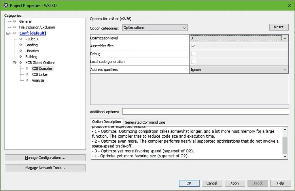
Actually, nothing, we just need to change one more setting - optimization level. This is the parameter that tells the compiler how to optimize the code. The thing is the C language is not native for the MCUs, and it’s first translated into Assembly and then to machine codes. And the C operations and commands can be translated in many different ways. The optimization allows the compiler to merge or remove some instructions where it is possible, and thus reduce the code size. There are several optimization levels: 0, 1, 2, 3, and s. The higher the number, the deeper is the optimization, and “s” stands for the “size” which means the optimization that leads to the least code size. The 3rd level makes the operation speed as the highest priority, so we will use it.
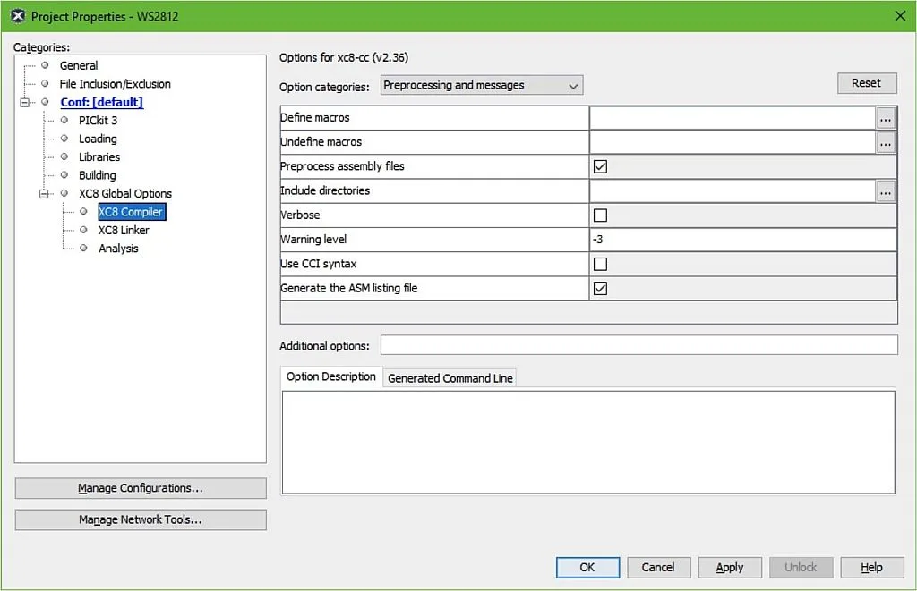
To change the optimization level, we need to open the project properties by right-clicking on the project name and selecting the “Properties” point. In the opened window we need to choose the XC8 Compiler point in the left part of the window (Figure 14).
Then in the “Option categories” drop-down list we need to select the “Optimizations” point and then choose the Optimization level “3” (Figure 15).
Then click OK, and compile and run the code one more time. Now everything should work as desired.
And now that’s really all. In this tutorial, we learnt how to configure the oscillator module, and how to control the WS2812B LEDs. Even though the PIC18F14K50 MCU doesn’t have enough speed, the range of the WS2812B timings allows it to successfully work with them.
As homework, I suggest you change the mode of the LEDs operation in any way you want: gradient, changing the brightness, switching the colors etc. But take into account that the operations with the colors should be short enough not to cause the LED reset state.
Next time we will return to the 7-segment indicator and make a digital thermometer based on it and a DS18B20 sensor.

Get the latest tools and tutorials, fresh from the toaster.


