What is an Open Collector Output?
Published
Have you ever heard reference to an “Open collector” or “Open drain” output when referring to an integrated circuit or a microcontroller? Have you ever wondered why the GPIO on your microcontroller doesn’t act the way you expect it to? Some devices, instead of driving an output high or low, simply change the impedance between their output and ground. Let’s review what this means, how it’s done, and why it’s important. We’ll start with open collectors and then discuss open drain, as they operate on the same principle.
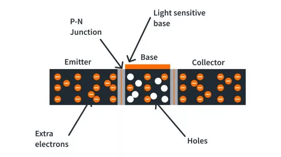
First, let’s quickly review bipolar junction transistors, or BJTs, though if you’d like to learn more in-depth about them, we have a tutorial about them we would recommend to learn all about them. For our purposes, it’s most important to note that there are three terminals - a base, emitter, and collector. You apply a voltage on the base and a little bit of current flows from the base to the emitter, but, more importantly, this allows a larger amount of current flows from the collector to the emitter at the same time. With this principle, you can use a BJT as a switch or an amplifier by using that relatively small controlling current through the base to make a much larger current flow from the collector to emitter.
When you hear that a microcontroller or integrated circuit (IC) uses an open-collector GPIO, it means that any device that is connected to the GPIO is actually connected to the collector of a BJT that is internal to the device. Thus, when the IC output is high or low, it’s simply controlling the impedance between the pin and ground - it’s not necessarily a high voltage or low voltage. Instead, you’re controlling whether it is high-impedance (or high-Z) or whether it is low-impedance (or low-Z). Indeed, if you have an open collector GPIO, if you want a high-voltage in the high-impedance state, you will need a pull-up resistor. Sometimes this is provided internally, sometimes it is not.

An open drain output is similar to an output collector but uses a MOSFET instead of a BJT. Much like there is a base, emitter, and collector of a BJT, in a MOSFET, there’s the gate, source, and drain. Again, if you’re not very familiar with MOSFETs, we recommend you go learn more about them from one of our other tutorials on the topic. For the open-drain output, the GPIO line is connected to the drain of a MOSFET internal to the device. The internal IC control is connected to the gate of the MOSFET, which can open or close like a switch. If there is a high voltage applied to the gate, then the switch closes, showing a low impedance between the drain and ground. If a low voltage is applied to the gate, then the switch opens and there is a high impedance between the drain and ground. Just like with the internal BJT, in a high impedance mode, if you want the GPIO at a high or low voltage, you’ll need a pull-up or pull-down resistor. Check with your datasheet to see if this is provided internal to the IC you’re working with or not. Pull-up resistors are significantly more common than pull-down resistors but other times the chip designer leaves it out so that you can control both the direction and the strength of pull by using your own external resistors.
The benefit of an open collector or open drain is that it is very effective for sinking current. To learn more about the difference between sinking and sourcing current, you can review our other tutorial on that topic. With an internal transistor connected directly to ground, it permits a much higher amount of current to flow through the low impedance connection than some other internal configurations you can find. This lower impedance along with lower capacitance and greater immunity to electrical noise is why open collector or open drain outputs are often used instead of the many different GPIO driving options available. As there are always tradeoffs in engineering, the drawback of open collector outputs is their relative weakness in sourcing current. While they can sink current very well, they are, for all practical purposes, completely unable to source current with an internal NPN BJT transistor. Of course, an internal PNP BJT transistor can act as a current source but then that form does very poorly when it comes to sinking current.
We hope that this brief overview of what an open collector or open drain system is will help you understand the next time you come across these. Knowing the internal configuration of these devices, the similarities between open collector and open drain configurations, and how they operate in the different states will help you make better decisions about whether or not you want this type of outputs and if so, how to properly utilize them.

Get the latest tools and tutorials, fresh from the toaster.


