How Resistors Work: Understanding the Fundamentals of Resistance
Published
Resistors are the most common electronics component in the world. They’re used in many forms of circuits as voltage dividers, to keep current levels under control with things like LEDs, to set the gain with amplifiers, and many, many more things. With that, what are resistors and what do they do?
What does a resistor do?

Resistors have a wonderfully practical name - they literally resist the flow of electrons. In previous tutorials and videos, we talked about the nature of electricity and the way that electrons want to spread out and be as far apart from each other as possible. That desire for the electrons to be somewhere with less electron density is voltage and, without resistance, electrons would very quickly equalize everywhere. In reality, everything has resistance, which basically impedes, or limits, that flow of electrons from one place to another. The higher the resistance, the greater potential that needs to be overcome before the electrons start moving.
Resistors follow Ohm’s Law - a law that relates the voltage, current flow, and resistance.

or

So, voltage equals the resistance times current. But, for understanding intuitively what is going on, I prefer to think of it as current is equal to voltage over resistance. So, as voltage increases (the electron density differential increases) or the resistance decreases (the difficulty of the electrons to move) the current increases (amount of electrons flowing).

We also have another tutorial that uses a different example to help you understand the relationship between voltage, current, and resistance, if this is still not clear.
The simplest form of this equation is that if voltage is equal to 1 volt and resistance is equal to 1 ohm, there will be 1 amp of current. To get 2 amps of current, you can either increase the voltage to 2 volts or decrease the resistance to 0.5. Or increase the voltage to 1.5 and decrease the resistance to 0.75, if you want to. Either way - it’s a very linear relationship and extremely easy to use. But, the takeaway is, in some situations you can change the voltage, in others, you can change the resistance. In more uncommon cases, you can even change the current. The world is your oyster! But, typically you change the resistance to make whatever current you need.
So, what does it look like?
Now that you know what a resistor does, let’s look at how resistors are represented in schematics. These are symbols only and have no bearing whatsoever on how a resistor looks in real life. But, to help you remember, you can think that the squiggly lines slow down the electrons, thereby “resisting” their flow. Obviously, this is not what happens in real life but if it helps, there’s no harm in imagining it.

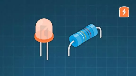
Unfortunately, while there are only a few ways to represent resistors, actual resistors change a lot. They can be big and heavy or smaller than a grain of sand. They can be a variety of colors, shapes, connection styles, without it having any effect on their resistance. That being said, those size differences can be very important in other ways. Before we get into that, here are a couple examples of different resistors.

What are the important parameters of a resistor?
1. Power Rating
It may seem strange that there are so many different types and sizes of resistors. In the power dissipation tutorial, you can learn more about how important it is to consider power in your circuit, but for right now, just know, it’s important. And tiny resistors can’t handle the power that a resistor the size of a loaf of bread can.
2. Resistance
Being able to select the resistance you want is hopefully pretty obvious. But it’s important to think about! Resistors come in “common” values, depending on their tolerance (covered below) the common values are different. 5% tolerance is typical, and for these, the resistor values look like this:

You can see that the space between common values is not even and you miss certain whole numbers, like 4, 5, 6, 7, 8, and 9. So, when you’re choosing a resistor value in your design, you don’t want to choose 800 ohms, as the closest values are 750 or 820. Then you’ll be looking for a more expensive, higher tolerance resistor, which may be avoidable.
3. Tolerance
As mentioned in the last section, an important aspect of resistors is their tolerance. This is how far the actual, measured resistance deviates from the nominal resistance. For example, a 100Ω resistor with a ±5% tolerance means that it could actually range from 95Ω to 105Ω.
While 5% is quite common, you can get down to ±0.01% and up to ±30%! As a general rule, the tighter the tolerance, the higher the cost and the greater granularity you can get in choosing the values.
Now the strange spacings of the resistors makes more sense! Using the example of 820Ω, let’s multiply that by 0.95 and 1.05. We get 779 and 861, which is why we wouldn’t want or need an 800Ω resistor, as the tolerances cover that entire range. 750 x 1.05 = 787.5, so not only does that cover the gap between the two resistors, technically, a 750Ω 5% tolerance resistor can have a higher resistance than a 800Ω 5% tolerance resistor.
The reality is that most 5% resistors are actually quite close to the nominal value - frankly, there have been only very rare occasions for me when I’ve found a resistor off by more than 1%. But a higher tolerance resistor is guaranteed to be within that tolerance level. There’s a very large difference between me working in my basement making a prototype versus creating a product that will be mass produced in the millions, where each faulty product costs an enormous amount of money, time, and reputation.
4. Temperature Coefficient
While most of the work we do in the lab is relatively stable in temperature, resistors are required to work in a huge variety of temperature extremes. Near the cryogenically cooled superconductor cables of things like MRI machines to the control panels of smelting plants, the temperatures these things face are crazy. So, what happens when a resistor acts one way at room temperature and another way when it’s below freezing? Typically, not good things.
For this, manufacturers put a temperature coefficient of resistance, usually measured in parts per million, or “ppm”. This means that for every degree above or below nominal temperature, the resistance won’t deviate by more than a couple millionth of an ohm. This is typically in Celsius or centigrade.
As an example:
Assume a resistor is rated for 30 ppm/°C, it will only change by 30 millionths (0.000030) of the original value of the resistor per degree Celsius. If I have a 100 ohm resistor and assuming room temperature is 25°C, then if the temperatures rises to 100°C, we will get the following:


So the final value would be between 99.775Ω or 100.225Ω.
5. Capacitance and Inductance
A perfect resistor has no capacitance and no inductance. But nobody’s perfect - don’t take it personally. All resistors have a very minute amount of capacitance and inductance. Frankly, unless you’re doing something like RF or antenna design, you can ignore this. The amount of exceptions to that statement are so minimal I’m going to stand by it. However, I bring it up because 1) it does exist and 2) you may, eventually, want to do some antenna design (or at least implementation), perhaps with a PCB stripline antenna or something. If it’s not working right, make sure to consider all sources of inductance and capacitance.
Summary
Resistors are really quite straightforward and there isn’t too much to stress about! However, we dropped a lot into this to let you know that there are more things out there that can affect your design in certain situations. But now that you know about them, it shouldn’t be a problem. Go forth and have some fun with those resistors!
Check Yourself
7 Questions
Tutorial FAQs
Because the resistor forces the water through a smaller gap, does the voltage required to get electrons through the gap increase and therefore, that's how resistors use up some of the voltage supplied to the circuit?
This is where having an intuitive understanding of Ohm's Law is really helpful! With V=IR, you can see that if resistance increases (the pipe gets smaller), and you want to keep current the same (same amount of water flowing through), then yes, voltage would need to increase (increase the height or potential of the water).
But, in a real circuit, you're typically working with a given voltage source so that voltage won't change (For example, 1.5V for a single alkaline battery, 5V for a USB power source, 3.7V for a lithium-ion battery, etc.) So, if resistance goes up or down, current also goes up or down.
On the diagram you showed of water going through a pipe, all the water that hit the narrower part of the pipe went through, and that confuses me. Because, to my understanding, resistors are supposed to reduce the current (water) going through the wire (pipe) but with what you showed, it did not reduce the amount of water going through the pipe. What's going on here?
The resistors reduce the current by restricting the flow of electrons. At around the 3:40 mark, you notice the flow through the "resistor" which is the narrow part of the tube. How that restricts the flow is, imagine if that narrow part of the tube were 4 times as wide, how much more water would be flowing from the top to the bottom? So, it does reduce the amount of water (or "current") to a controlled flow.
The second question is really good - the resistors reduce the amount of current through that point. Whether or not there is more current elsewhere in the circuit depends on how the circuit is set up. If there is something else "downstream" or "upstream" in series, then the current through those other items will be the same as through the resistor. If there are other elements in parallel, or different voltage/current sources, then there will be different paths for the current to follow. That's when you start needing KCL/KVL (Kirchhoff's circuit laws) to start calculating values.
Because a resistor reduces the amount of electrons able to pass through it, what happens, physically, to the electrons that can't get through? Is there some sort of buildup? Do the electrons disperse somehow?
The electrons that can't get through simply stay where they are. They don't build up, however, as that would mean that they're increasing the voltage potential. This may be a weird way to say it but all the electrons that want to go through the resistor, go through the resistor. If the voltage is higher, if more electrons wanted to go through, more electrons would pass through.

Get the latest tools and tutorials, fresh from the toaster.


