How to use a Bipolar Junction Transistor (BJT) as a Switch?
Published
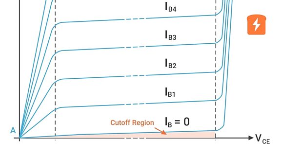
If you have checked out our tutorial Different Regions of BJT Operation, we’ve discussed how a bipolar junction transistor (BJT) operates in cutoff, saturation, and active regions. We have discussed the conditions in order for a BJT to operate in those different regions. In this tutorial, we will discuss how to utilize these two operating regions, cutoff and saturation, so that we can use a BJT as a switch. After completing this tutorial, you should be able to use a BJT for simple switching applications.
But before that, if you’re new to electrical or electronics engineering and you don't have any idea what a switch is, let’s first briefly discuss what it is. You can just skip the next part if you are already familiar with switches.
What is a switch?
Usually, the image that would appear in your mind when you think about a switch would be the image shown in figure 1. This type of switch is an electrical switch that we usually use in our homes to turn ON or OFF the lights.

There are a lot of types of switches used in electrical or electronics applications. We can categorize them mainly into electromechanical and electronic switches. Since a BJT operates like an SPST switch, we can just use an SPST toggle switch to easily explain how a switch works.

A switch is an electrical or electronic device that can open or close a circuit, stopping or allowing the flow of current in a circuit. In figure 2, you can see a single-pole, single-throw (SPST) toggle switch and the circuit symbol of an SPST switch. The number of poles in a switch determines how many separate circuits the switch can control while the throw-count of a switch tells us how many positions each of the switch’s poles can be connected to. An SPST switch has one pole and one throw, so it can only control one circuit and its pole can be connected to one terminal only. So basically, an SPST toggle switch is simply an ON-OFF switch with two terminals (A & B) that can be connected together or disconnected from each other by toggling the lever (actuator).
In figure 3, we can see a schematic diagram of a light bulb connected directly to the AC mains. I hope you can imagine it, in reality, the light bulb is connected to the AC mains or wall outlet through an electrical plug and zip-cord. So to turn ON the light bulb, we’ll insert the electrical plug to the outlet and to turn it off, we’ll disconnect the plug from the outlet. To make it less of a hassle, we can insert a toggle switch in the circuit so that we can just toggle the lever of the toggle switch if we want to turn ON or OFF the light bulb, instead of connecting or disconnecting the electrical plug.

As shown in figure 4, we can cut one line of the cable and insert the switch.

In figure 5, the switch is now inserted and the light bulb can be easily turned ON or OFF by just toggling the lever of the toggle switch. And that’s just how easy a switch works.

Comparing a BJT to an SPST Toggle Switch
In figure 6, the SPST toggle switch has three parts or labels that we can compare to the BJT three terminals. The collector and emitter terminals of the BJT are like terminal A and B of the toggle switch. The base terminal of the BJT is similar to the lever of the toggle switch. We will discuss this more later.

Why do I need to use a BJT for switching?
There are plenty of reasons why you would use a BJT or a transistor as a switch. But for me, I think the main reason is driving a load with higher current consumption or voltage. For example, your load requires 100mA but you can only draw 20mA from your source, which is common for a GPIO pin of a microcontroller. Or maybe you need to drive a 12V relay using a microcontroller but its pin can only output 3.3V or 5V. You can use a transistor to solve that problem.
By using a transistor to switch bigger loads, you can also automate the process of switching or switch ON or OFF the load remotely instead of using an electromechanical switch which needs to be hand-operated. So with those reasons, let’s start discussing the switching operation of a BJT.
BJT Switching Operation
The operation of a BJT as a switching device is really easy to understand especially if you have already learned how to make a BJT operate in the cutoff and saturation region. A BJT acts like an open switch when it operates in the cutoff region. In figure 7, you can see that the npn BJT is operating in the cutoff region since the voltage at the base terminal is 0V. Therefore, the base-emitter junction is not forward-biased and if we will not consider the leakage current, all of the currents, IB and IC are zero. You can also see in figure 7 that the collector and emitter terminals act like an open SPST switch. Since IC is zero, the voltage across the collector and emitter terminal, VCE(cutoff), is equal to VCC.

So for a BJT to act as an open switch, all you need to do is to make sure that its base-emitter junction is not forward-biased. Now, for a BJT to act as a closed switch, it needs to operate in the saturation region. In figure 8, we’ve assumed that the npn BJT is operating in the saturation region. As you can see, the collector and emitter terminals act like a closed SPST switch. Ideally, there’s basically a short between the collector and emitter and the voltage drop across it should be zero. However, in reality, there is a small voltage drop across the collector and emitter terminals which is known as the saturation voltage, VCE(sat).

For a BJT to operate in the saturation region, the base-emitter junction and base-collector junction should be forward-biased, and there should be a sufficient base current to produce the collector saturation current, IC(sat). Using the circuit in figure 8, the formula to calculate the IC(sat) is:

IC(sat) is the current that the load RC requires. VCE(sat) is specified in the datasheet of the BJT that you are going to use. After calculating IC(sat), the next thing to figure out is the minimum base current, IB(min), needed to make sure to produce IC(sat). You can use this equation to calculate IB(min).

To make sure that the BJT is operating in the saturation region, you just need to make sure that IB is greater than IB(min).
What DC Beta to use?
Now, if you know the VCE(sat) of the BJT, the voltage drop across the load and its resistance, you can calculate IC(sat) then calculate IB(min). However, you may wonder, what’s the value of βDC? To make it easier for you to find out, the clue is you can find βDC on the BJT datasheet that you will use. So okay, let’s check the datasheet of a very commonly used npn general purpose transistor, the 2N3904.

If you checked the datasheet of 2N3904, you can find something that is similar to what is shown in figure 9. Since DC beta (βDC) is equivalent to the hybrid parameter (hFE), you may think that this is where you are going to get the value of βDC to solve for IB(min). However, hFE in figure 9 is the current gain of a BJT that is operating as an amplifier or in the active region. The values that you should be checking are values where the BJT is in the saturation condition.

In figure 10, you can see the different values and information about the 2N3904 operating at saturation region. These are all from the datasheet. Based on this information, you will see that the βDC used in the saturation region for the 2N3904 is 10. Notice that the IC/IB ratio is always 10?
Not all BJTs use 10 for βDC though so far, most of the transistors I’ve used use 10. Darlington BJTs like TIP120 have a 250 IC/IB ratio. But for 2N3904, the guaranteed value of βDC is 10 for it to operate in the saturation region. Some may use 20 but as we’ve discussed in the Different Regions of BJT Operation tutorial, βDC is not constant and it changes with the junction temperature. So it’s better to set βDC at 10.
Application
So, to see how a BJT operates as a switch in real life, let’s try this simple application. Let’s say, we need to drive a 12V load with 50mA current consumption using an Arduino Uno. Since the GPIO pin of the Arduino Uno can only output 5V maximum of 20mA, if the conditions in the ATmega328P datasheet are strictly followed, in this case, we need to use a transistor switch. For this demonstration, I will just use a dummy load which will be composed of 5 LEDs with series resistors in parallel. Each LED will draw 10mA, so times 5, gives a total of 50mA.

Let’s see what values we already have here and the values that we still need to solve. I hope you already have the basics of circuit analysis. However, if not yet, we have tutorials for that. You can check them out here: CircuitBread Circuit Theory Tutorials
In this example, we already know that IC(sat) is 50mA and 2N3904 βDC is 10. So IB(min) is just:

If you check 2N3904 datasheet or figure 10 again, you’ll see that at 50mA IC, the maximum possible VCE(sat) is 0.3V and VBE(sat) is 0.95V. I1 to I5 here are all the same which is equal to IC(sat)/5 = 50mA/5 = 10mA. The LEDs that I’m going to use here are yellow LEDs which have a typical forward voltage of 2V. The output voltage of the Arduino Uno GPIO pin is approximately 5V. So the values that we need to solve here are R1 to R5 which all have the same resistance and RB. So let’s solve R1 to R5 first:
Using KVL at the collector and emitter side,


Using Ohm’s Law,


R2 to R5 are all 970Ω too. Now, let’s solve RB:
Using KVL again at the base and emitter side,


Using Ohm’s Law again,


The values above are calculated using ideal conditions. However, please understand that in reality, the devices that we’re using are not perfect so there might be a small difference between the calculated values and the actual readings in the multimeter. So here’s the actual result:


As you can see in figures 12-14, we have the Arduino Uno, 2N3904 npn BJT, five yellow LEDs, five 970Ω resistors (two 1kΩ resistors in parallel in series with a 470Ω resistor), five 810Ω resistors (120Ω, 300Ω, and 390Ω resistors in series), and the 12V power supply. The Arduino Uno here is simply programmed to output low when D2 pin is high and to output high when D2 is low or connected to ground. In figures 12-14, D2 pin is high, so D5 pin is low. Therefore, the base-emitter junction of the 2N3904 transistor is not forward-biased making the transistor operate in the cutoff region or as an open switch. No current flows through the collector terminal so the load is OFF.

In figure 15, you can see that the D2 pin of Arduino Uno is connected to ground so the output of the D5 pin is high. This makes the base-emitter junction and the base-collector junction forward-biased and the 2N3904 transistor operates in the saturation region. As you can see, the LEDs are now ON.

Figure 16 shows the voltage output of the D5 of the Arduino Uno. Ideally it should be 5V but in reality it’s only 4.88V. But it’s not really a big deal.

In figure 17, the multimeter shows the voltage drop across the base-emitter junction of the 2N3904. The datasheet shows 0.95V max but in this circuit design, VBE(sat) is 0.836V.

In the datasheet, the maximum VCE(sat) at 50mA IC is 0.3V. However, in this application VCE(sat) is just 165.4mV as shown in figure 18. The smaller the voltage drop across the collector and emitter terminals the better, because that means there will be less power wasted in the transistor.

Figure 19 shows the base current which is 4.98mA. Ideally, this should be 5mA.

Figure 20 shows the current measured by the multimeter through the collector. Ideally, this should be 50mA but in reality, the measurement shows 50.2mA.

Figure 21 shows the voltage drop across the LEDs series resistor, R1 to R5, which is 9.9V.

I’ve mentioned earlier that the typical forward voltage of a yellow LED is 2V and in figure 22, the multimeter shows a 1.981V voltage drop across the LEDs which is close to 2V. The voltage drop across RB, 4.07V, is shown in figure 23.

Now, to check if the BJT is really operating in the saturation region, in figure 24, I have removed the 390Ω resistor at the base terminal side to increase IB more. As you can see, the current measured by the multimeter in figure 24 is 9.10mA. This is almost double the minimum base current required to make the transistor operate in the saturation region.

But in figure 25, you can see on the multimeter display that the collector current remains almost the same. At 4.98mA base current, the collector current is 50.2mA as shown in figures 19 and 20. In figure 25, the measured current is 50.3mA even though the base current has increased to 9.10mA.

This shows that the BJT is really operating in the saturation region because even though IB is increased, the value of IC(sat) didn’t increase anymore.
Summary
So we’re done with the tutorial! We've discussed how a switch works and compared a BJT to an SPST toggle switch. We've learned why we need to use a BJT for switching and have discussed the switching operation of a BJT. We went over the calculations to get the most efficient switching possible. I hope the application helped you understand more how a BJT works in real life, so hopefully you can now use BJTs for simple switching applications. Also, when selecting a BJT to use in your projects, always check the datasheet of the BJT for maximum ratings. Make sure you don’t exceed the maximum ratings so you won’t damage the BJT and other parts of your project. I hope you’ve found this tutorial interesting or helpful. If you have any questions, leave it in the comments below. Also, please subscribe to CircuitBread Youtube channel. See you in our next tutorial!

Get the latest tools and tutorials, fresh from the toaster.

