Wave Propagation on a TEM Transmission Line
In Section 3.6, it is shown that expressions for the phasor representations of the potential and current along a transmission line are


where

is the propagation constant and it assumed that the transmission line is aligned along the

axis. In this section, we demonstrate that these expressions represent sinusoidal waves, and point out some important features. Before attempting this section, the reader should be familiar with the contents of Sections 3.4, 3.6, and 3.7. A refresher on fundamental wave concepts (Section 1.3) may also be helpful.
We first define real-valued quantities

and

to be the real and imaginary components of

; i.e.,


and subsequently

Then we observe

It may be easier to interpret this expression by reverting to the time domain:

Thus,

represents a damped sinusoidal wave traveling in the

direction, and

represents a damped sinusoidal wave traveling in the

direction.
Let’s define

and

to be the potential and current associated with a wave propagating in the

direction. Then:

or equivalently in the time domain:

where

is the phase of

.

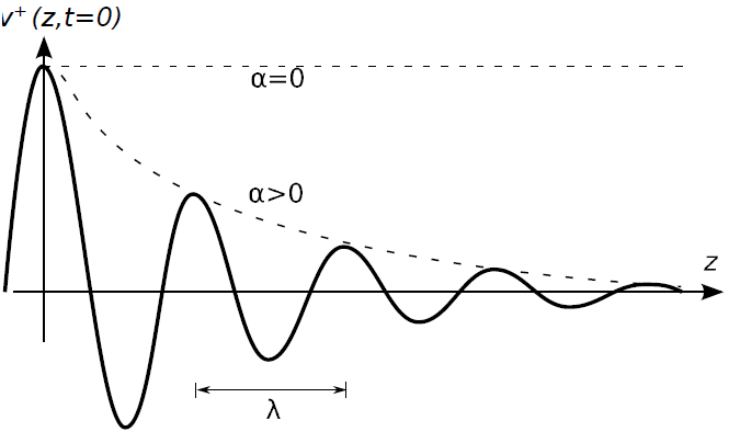
Figure 3.8.1: The potential

of the wave traveling in the

direction at

for

.
Figure 3.8.1 shows

. From fundamental wave theory we recognize.

(rad/m) is the phase propagation constant, which is the rate at which phase changes as a function of distance.
Subsequently the wavelength in the line is

Also we recognize:

(1/m) is the attenuation constant, which is the rate at which magnitude diminishes as a function of distance.
Sometimes the units of

are indicated as “Np/m” (“nepers” per meter), where the term “neper” is used to indicate the units of the otherwise unitless real-valued exponent of the constant

.
Note that

for a wave that does not diminish in magnitude with increasing distance, in which case the transmission line is said to be lossless. If

then the line is said to be lossy (or possibly “low loss” if the loss can be neglected), and in this case the rate at which the magnitude decreases with distance increases with

.
Next let us consider the speed of the wave. To answer this question, we need to be a bit more specific about what we mean by “speed.” At the moment, we mean phase velocity; that is, the speed at which a point of constant phase seems to move through space. In other words, what distance

does a point of constant phase traverse in time

? To answer this question, we first note that the phase of

can be written generally as

where

is some constant. Similarly, the phase at some time

later and some point

further along can be written as

The phase velocity

is

/

when these two phases are equal; i.e., when

Solving for

, we obtain:

Having previously noted that

, the above expression also yields the expected result

The phase velocity

is the speed at which a point of constant phase travels along the line.
Returning now to consider the current associated with the wave traveling in the

direction:

We can rewrite this expression in terms of the characteristic impedance

, as follows:

Similarly, we find that the current

associated with

for the wave traveling in the

direction is

The negative sign appearing in the above expression emerges as a result of the sign conventions used for potential and current in the derivation of the telegrapher’s equations (Section 3.5). The physical significance of this change of sign is that wherever the potential of the wave traveling in the

direction is positive, then the current at the same point is flowing in the

direction.
It is frequently necessary to consider the possibility that waves travel in both directions simultaneously. A very important case where this arises is when there is reflection from a discontinuity of some kind; e.g., from a termination which is not perfectly impedance-matched. In this case, the total potential

and total current

can be expressed as the general solution to the wave equation; i.e., as the sum of the “incident” (

-traveling) wave and the reflected (

-traveling) waves:


Ellingson, Steven W. (2018) Electromagnetics, Vol. 1. Blacksburg, VA: VT Publishing. https://doi.org/10.21061/electromagnetics-vol-1 CC BY-SA 4.0
Explore CircuitBread

Get the latest tools and tutorials, fresh from the toaster.


