Bridge Full-Wave Rectifier Operation
Published
In our discussion with half-wave rectifiers, we’ve learned that half-wave rectifiers only rectify the half-cycle of the AC input. Though they can be used in some applications, most DC power supplies that you can find use full-wave rectifiers. In this conceptual tutorial, we will discuss the operation of a full-wave rectifier and its one type, the bridge full-wave rectifier.
Full-Wave Rectifier
One of the reasons why full-wave rectifiers are much preferred than half-wave rectifiers is because full-wave rectifiers rectify both positive and negative half-cycles of the AC input. This makes them more efficient than the half-wave rectifiers. Since full-wave rectifiers rectify the entire 360 degrees of the input, their output has an average value and frequency twice of the output of half-wave rectifiers (see figure 1).
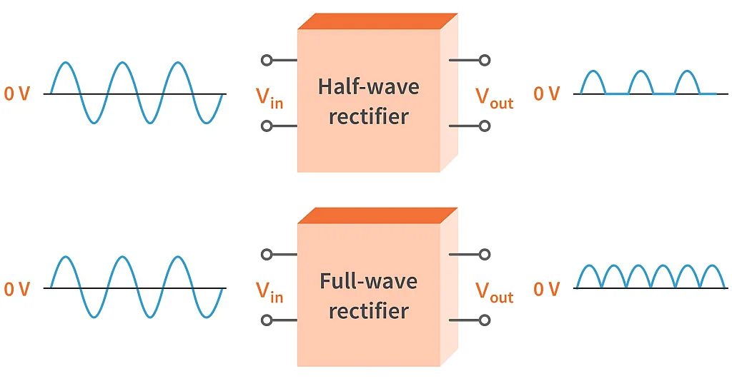
There are two types of full-wave rectifiers: bridge and center-tapped. But for now, we will just focus on the bridge type and discuss the center-tapped rectifier in another tutorial.
Bridge Full-Wave Rectifier Operation
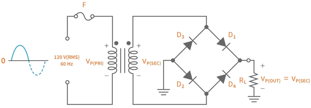
While a half-wave rectifier uses only a single diode, a bridge type full-wave rectifier uses four diodes, as you can see in figure 2. It uses four diodes in a bridge topology for it to be able to rectify both the positive and the negative half-cycles of the AC input.
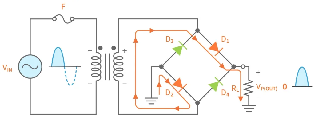
So here’s how the bridge rectifier operates (see figure 3). During the positive half-cycle of the input, D1 and D2 are forward-biased while D3 and D4 are reverse-biased. As you can see in figure 3, the current from the positive side of the transformer's secondary winding flows through D1 and enters the load. This develops a voltage across the load. From the load, the current enters D2 through the ground and then returns to the negative side of the secondary winding.
When the AC input switches to negative half-cycle, the polarity across the secondary winding of the transformer is reversed and also the flow of the current (see figure 4). This time, D1 and D2 are reverse-biased while D3 and D4 are forward-biased. During the negative half-cycle, from the positive side of the secondary winding, the current flows through D4 and enters the load. Notice that the direction of the current when it enters the load is just the same on the direction during the positive half-cycle. So the output voltage across the load is still in the same direction though the input voltage is negative.
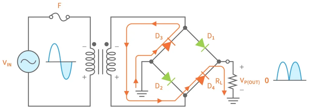
Here you can see that the output of a bridge full-wave rectifier is really DC, though it is still a pulsating DC. From the load, the current enters D3 through the ground and returns to the negative side of the secondary winding of the transformer. So the output across the load after an entire cycle is a full-wave rectified output voltage.
Average Value
As mentioned earlier, the average value of a full-wave rectified voltage is twice of a half-wave. So to calculate the average value, you can use this equation:

Peak Output Voltage
The peak output voltage of a bridge rectifier, VP(OUT), which appears across the load (RL) is equal to the peak voltage of the secondary winding of the transformer if we consider the diodes ideal. However, in reality, there’s a voltage drop across a diode whenever current flows through it. For a silicon diode, let’s assume that the voltage drop is 0.7V.
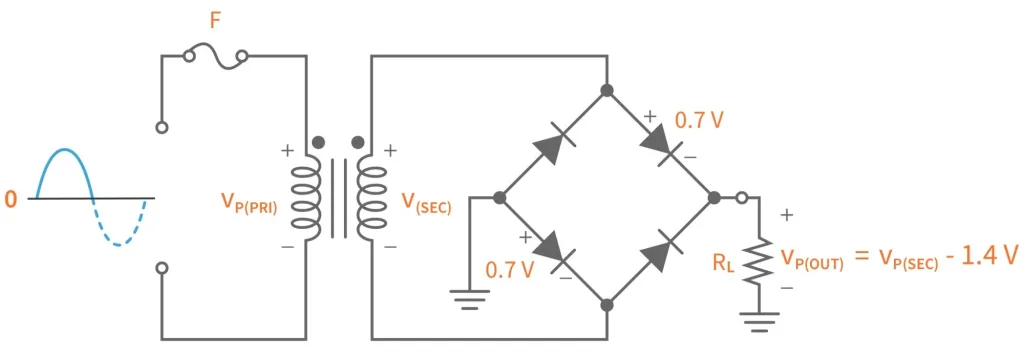

If you’re going to observe the operation of a bridge rectifier, you’ll notice that the two diodes that conduct during positive and negative half-cycles are in series with the load. So the peak output voltage across the load would be the peak voltage of the secondary winding minus the voltage drop across these diodes.
Peak Inverse Voltage
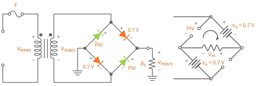

Now let’s try to determine the peak inverse voltage (PIV) that the bridge rectifier diodes must withstand if they are in a reverse-biased condition. Assuming that the input is now in positive half-cycle, so D1 and D2 are forward-biased while D3 and D4 are reverse-biased. You can clearly see in figure 6 that the PIV is equal to the sum of the peak voltage across the load and the forward voltage of one diode. So to be safe, you can select a diode that has a PIV that is at least twice of that value.
Summary
In this tutorial, we've discussed the full-wave rectifier and compared it to the half-wave rectifier. We have also mentioned its two types, bridge and center-tapped, and discuss how the bridge rectifier operates. If you’ve found this tutorial interesting or helpful, give it a like and if you have any questions, leave it in the comments below. See you in our next tutorial!
Check Yourself
10 Questions

Get the latest tools and tutorials, fresh from the toaster.

