Create a Real-Time Clock with OLED Display Using I2C Module using MCC | Embedded C Programming - Part 35
Published
Project Files
Hello again!
After the last tutorial where we didn’t study any new modules, we are opening the next subseries devoted to the digital interfaces of the PIC18F14K50 MCU, using the Microchip Code Configurator or MCC. The PIC18F14K50 has several integral hardware communication modules: I2C, SPI, UART, and USB, all of which we’ve discussed at a conceptual level in our communications series.
Moreover, starting from this tutorial until the last one of the series, we will use the Universal board I introduced in Tutorial 27. If you don’t have this board, you can just keep using the breadboard and separate parts, it’s totally fine. Or, if we get enough interest, we may produce them in bulk and you can purchase one from us, or, if you’d like, you can assemble one yourself. But once you start using it, believe me, you will not want to return to separate parts again.
This tutorial will be somewhat meaty. We will create a clock and calendar using the DS1307 RTC chip. To indicate the time and date, we will use a 64x32 OLED display with the SSD1306 driver. All these parts are already populated on the Universal board, so we don’t need to look for them (if you do, you might want to purchase the Arduino DS1307 RTC module (Figure 1) and the OLED module (Figure 2) on any marketplace (Amazon, ebay, Aliexpress)).
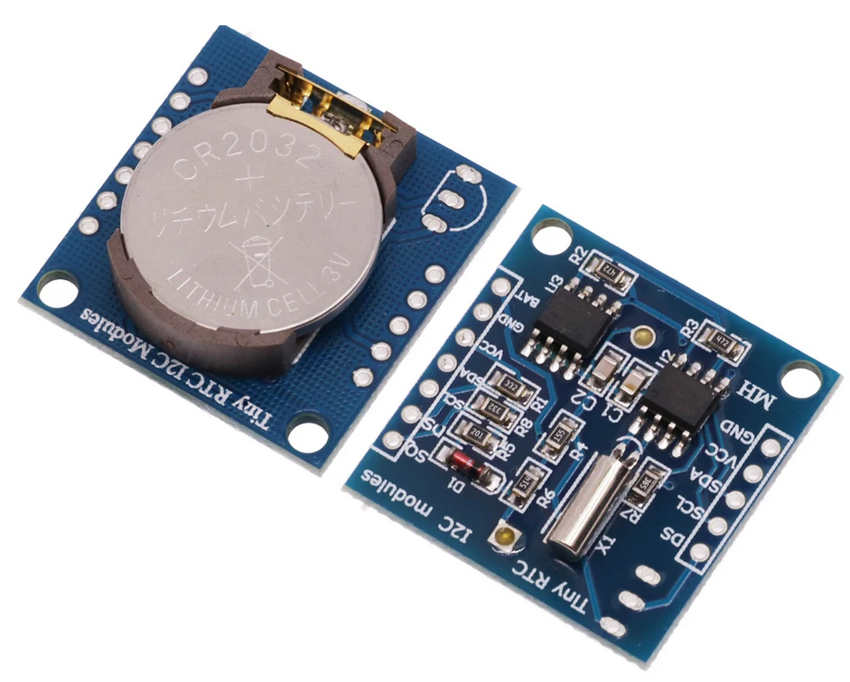
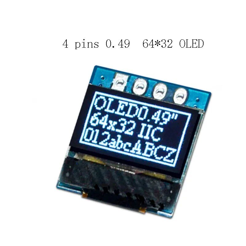
The price of each module is about $1.5-2 USD so this purchase most likely will not be painful for your wallet.
Both the RTC and display use the same communication interface, I2C, which fortunately is supported by the PIC18F14K50 with its dedicated I2C module.
We already used the I2C interface in the PIC10F200 tutorial when we created the FM radio. There you also can find a brief description of this interface. For a more detailed description, please refer to this tutorial. And in this lesson, I will not describe the interface itself considering you can familiarize yourself with it in the linked PIC10F200 tutorial as well as the communications tutorials I mentioned at the beginning.
So the task for this tutorial will be quite simple - create a digital clock and calendar which will be able to display and adjust the current time and date. But the program which implements this short task will be quite long and complex.
But before starting considering the code, let’s first get familiar with the I2C module used in the current project. Even though the operation of this module is not very hard, it has a lot of functions, so its description will take some time.
Master Synchronous Serial Port (MSSP) Module
As you can see, the module is called the “MSSP” instead of I2C which means that things are already more complicated than we originally anticipated. With the PIC18F14K50, there is a joint I2C + SPI module which is called the MSSP. And there is only one such module in this MCU. Which means (as you might already have guessed) that you can’t use both I2C and SPI interfaces in the same project. This is another flaw of this MCU (this makes us wonder why we use this chip sometimes) but as I usually say - we have what we have.
In this tutorial we will consider operation of the MSSP module only in I2C mode, and leave the SPI mode for the next one.
In its defense, this module is quite advanced so it may be worth it. Let’s see what it supports.
It has full hardware support of the I2C master and slave modes. For the master mode, it provides detection of start and stop bits which gives us the means of organizing the multi-master bus. In slave mode, it supports 7-, and 10-bit addressing along with the general calls. With such a vast functionality, it’s not surprising that this module uses 7 registers for I2C operation.
Luckily for us, the MCC-based interface of I2C is very simple for the programmer (but it’s quite tangled inside). It took me more than an hour to understand how it all works, but it’s not necessary for you to do it, as you can just use the final API function without digging deeply. For this module, MCC provides not only the peripheral driver like for the modules we have considered before but also the library which works above this driver and simplifies its use.
At this point, we will finish consideration of the MSSP module. If you are curious enough, please refer to Chapter 15.3 of the PIC18F14K50 data sheet for more information. Now, let’s briefly consider the new chips we will use in this tutorial.
DS1307 RTC Chip
DS1307 is a special chip which provides a real-time clock and calendar. Why do we need an external chip if we can use a regular timer to count the seconds, and then minutes, hours, days, months, and years? Well, it's always good if some functionality is performed at the hardware level that doesn’t include the processor. Many 32-bit MCUs have a built-in RTC module which eliminates the need of an external chip but the PIC18F14K50 doesn’t have one, so we use this DS1307 chip.
Let’s use the words from the datasheet of the DS1307 IC to describe its functionality. “The DS1307 serial real-time clock (RTC) is a low-power, full binary-coded decimal (BCD) clock/calendar plus 56 bytes of NV SRAM. Address and data are transferred serially through an I2C, bidirectional bus. The clock/calendar provides seconds, minutes, hours, day, date, month, and year information. The end of the month date is automatically adjusted for months with fewer than 31 days, including corrections for leap year. The clock operates in either the 24-hour or 12-hour format with AM/PM indicator. The DS1307 has a built-in power-sense circuit that detects power failures and automatically switches to the backup supply. Timekeeping operation continues while the part operates from the backup supply.”
What is important in this description for us as users? DS1307 provides all the day and the time values with the correct month lengths and the leap year correction. It has a backup power circuit which lets the IC keep the time even while the main power is off. By the way, you can see this backup power battery in Figure 1. This single CR2032 battery can keep the time for several years.
The data in DS1307 is represented in the BCD format which, on one hand, simplifies splitting the number into digits and, on the other hand, makes the process of setting the time more complex, which we will see in our program.
Let’s see the connection diagram of the DS1307 chip from its datasheet (Figure 3).
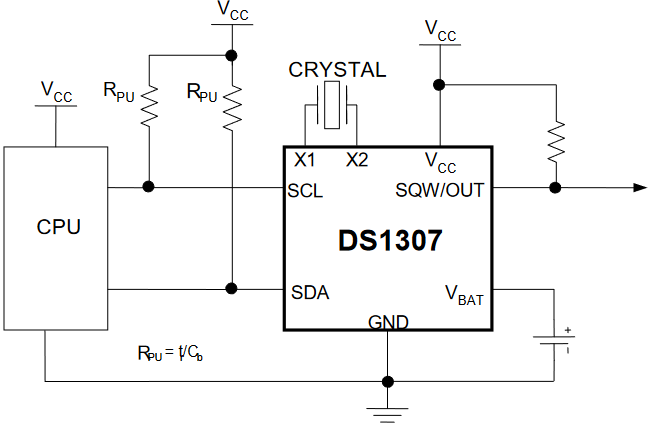
As you can see, the chip itself requires some external parts if you use it as a standalone IC. If you use a module like in Figure 1, all these parts are already mounted on the module. Among the mandatory parts there are:
- CRYSTAL - 32768 Hz crystal which is usually used in the quartz clocks, connected to pins X1 and X2 of DS1307. The accuracy of this crystal sets the accuracy of the whole clock, so if you do not want to adjust the time every day or week, select a crystal with a low frequency error.
- Pull-up resistors on the SDA and SCL pins which are required by the I2C standard.
The optional parts are:
- Pull-up resistor on the SQW/OUT pin. This pin is used to output square pulses of a defined frequency. We will use it in our device to define the time when we need to update the display with the new value.
- Backup battery connected to the Vbat pin. If you want your clock to keep counting when the power is down you need to install this battery. As I already mentioned, a regular 3V CR2032 battery will work out ideally for this purpose.
The power supply voltage for the DS1307 chip should be from 4.5 to 5.5 V though.
All the values of the DS1307 IC are stored in the internal registers accessible via the I2C bus through their addresses. The registers set (taken from the data sheet) is presented in table 1.
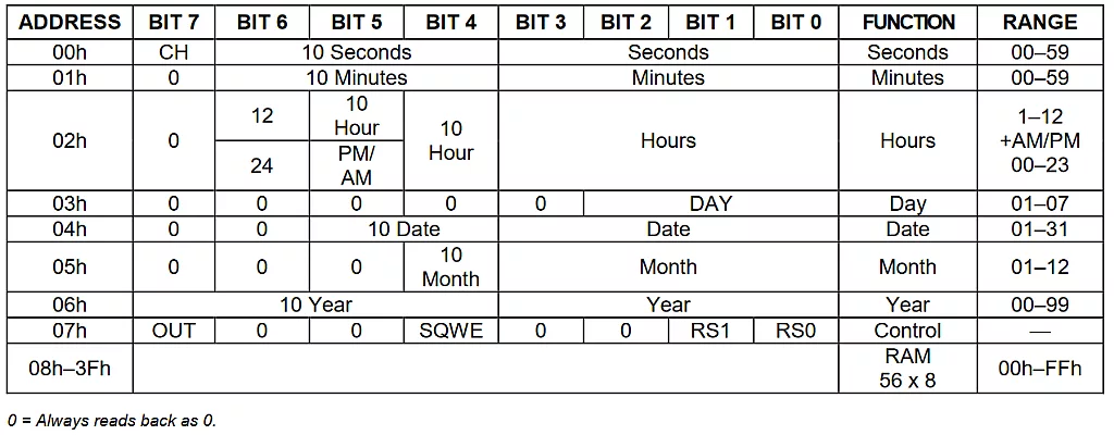
As you can see, the clock/calendar values are located at addresses 0x00-0x06 and are given in the BCD format, as I already mentioned. The register with the address 0x07 is the control register, it configures the functionality of the SQW/OUT pin.
Let’s consider it in more detail (yeah, yeah, there are registers everywhere, not only in MCUs).
- bit #7 - OUT. This bit controls the output level of the SQW/OUT pin when the square-wave output is disabled. If SQWE = 0, the logic level on the SQW/OUT pin is 1 if OUT = 1 and is 0 if OUT = 0. On initial application of power to the device, this bit is typically set to 0.
- bit #4 - SQWE. This bit, when set to 1, enables the oscillator output. The frequency of the square-wave output depends upon the value of the RS0 and RS1 bits. With the square-wave output set to 1Hz, the clock registers update on the falling edge of the square wave. On initial application of power to the device, this bit is typically set to a 0.
- bits #1-#0 - RS1-RS0. These bits control the frequency of the square-wave output when the square-wave output has been enabled. The following table lists the square-wave frequencies that can be selected with the RS bits. Upon initial application of power to the device, these bits are typically set to 1.

Also, please pay attention to the CH bit of register 0x00 (Seconds). This bit enables the oscillation and generally the time counting. After power up, this bit is ‘1’ and the RTC is stopped. To start its operation, we need to write ‘0’ into this bit.
Registers 0x08-0xFF are 56 RAM registers which the user can use as he wants. The content of this memory will be retained while either main or backup power are applied to the RTC chip.
That’s actually everything we need to know about the DS1307 chip to work with it. Now let’s consider the OLED display.
SSD1306-based OLED Display
The display we will use in this tutorial is a graphic display, unlike the 1602 LCD we used in previous tutorials which was a character display. This means that this OLED display doesn’t have any character generator. So now it’s our problem to generate the fonts (luckily for us there are already plenty of ready-made fonts which we can use). If we use the same 7x5 font used in the 1602 LCD, then each character will use 8 x 6 pixels (one extra pixel to avoid gluing of the characters) then having the resolution of the display of 64x32 pixels we can fit 4 rows of 10 characters each, so 40 characters in total. This is even greater than the 1602 LCD can fit despite the bigger size of the latter.
SSD1306 is the name of the driver which is very widely used in monochrome OLED displays of different resolutions from 16 x 32 to 64 x 128 pixels. It provides control of the LEDs of the display, generates the voltage required for the matrix operation, and allows communication with the MCU using either the I2C or SPI interface.
The full description of this driver is quite long, but if you are curious enough here’s the link to the datasheet. This driver has many more parameters than the HD44780 driver that controls the 1602 LCD which we considered in Tutorial 19.
So in regards to this display we will do things differently. We will take an existing SSD1306 library and adjust it for our MCU. There is a good Adafruit library developed for the Arduino platform which can be found here: https://github.com/adafruit/Adafruit_SSD1306. I already explained how to port this library to RA MCUs in the corresponding series. But for the PIC MCUs, there are several problems with this library. Firstly, it’s written in C++, which is not supported by the XC8 compiler, so we need to translate it from C++ to plain C. And the second related problem is that the class SSD1306 inherits from other classes which we also need to add and translate somehow. Considering all these difficulties, and the fact that after adding all the related functions, we can exceed the Flash memory volume, I decided to use the older version of their library. I downloaded it a long time ago when it was just a standalone class, and I don’t even know the number of its release. But I already translated it into the C languages and successfully ported it into many MCU families: MSP430 by TI, STM32 by ST, nRF51 by Nordic Semiconductor, EFR32 by Silicon labs, and probably others which I’ve already forgotten.
So in this tutorial I will provide you the source files of this library, explain its main functions and show the parts of the code which work directly with the hardware of the MCU. As you already probably assume, we will not deeply consider the library, we will just use it. But still, the code is open source, and it’s not very hard to understand, so if you are curious enough, feel free to discover (and probably upgrade) this library by yourself.
Now, let’s briefly consider the OLED module (Figure 2). As you can see, it has just four pins:
- GND - negative power pin
- VCC - positive power pin. Even though the display driver requires 3.3 - 3.6 V to operate, you can apply up to 5V to this pin, as there is an LDO voltage regulator on board.
- SCL and SDA - clock and data pins of the I2C interface.
If you want, you can buy a bare OLED and solder it by yourself, but be aware that it requires several external capacitors and resistors.
I will provide more information about the display work when we consider the code of the library, and for now let’s consider the schematic diagram of the device.
Schematic Diagram
Starting from this tutorial and till the end of this course we will consider two schematic diagrams - one with the regular parts, and another with the Universal board.
Schematic diagram with the regular parts is presented in Figure 4.

I made this schematic diagram based on an assumption that you will use the pre-assembled modules (like shown in fig 1, 2), not separate parts. But if you decide to use the bare DS1307 chip, please replace the DS1307 module according to Figure 3.
So, this schematic diagram consists of the PIC18F14K50 MCU (DD1) and two modules with DS1307 (X2) and OLED (X3). I specifically didn’t put the pin numbers of the modules as there are plenty of them and they might differ with the pinout, so please stick to the pin names, not numbers. Also, there are two push buttons - S1 for selecting the value to change and S2 for changing this value.
As you can see, the SCL and SDA pins of the modules are connected together and go to pins RB6 and RB4 of the MCU, respectively which are merged with the SCL and SDA pins of the MSSP module. The SQ pin of the DS1307 module is connected to pin RB7 and is used to trigger the MCU every second to let it know that it’s time to read the new value from the RTC and show it in the display. This approach allows us to eliminate any kind of timers to perform the delay between the display updates.
You may notice that there are no pull-up resistors on the SDA, SCL and SQ pins. They are already populated on the corresponding module. One may ask “Won’t there be any problems if there are pull-up resistors on both modules? Their resistance will be half that required by the I2C standard”. Well, I don’t think so. In some sources, resistances of 4.7-10 kOhm are mentioned, so it will be just fine.
Attentive readers also may notice the unconnected pins DS and BAT on the DS1307 module. The BAT pin is used if you want to use some external backup battery instead of the mounted one. The DS pin stands for DS18B20, which as you remember is a temperature sensor. The thing is that this module is multifunctional. It has the DS1307 RTS, the I2C EEPROM, and a spot for soldering the DS18B20 sensor (see three free pins in Figure 1).
Now let’s consider the schematics diagram based on the Universal board (Figure 5). If you don’t have one and are not going to get it, you may skip this section.
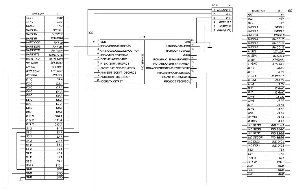
Well, this diagram looks quite big but in fact it has only the MCU DD1, the debugger X1 and the Universal board J6 and J7 (positions are taken from the board itself). Each part on the board is connected to these two 80-pin connectors, and marked correspondingly. The OLED display and the DS1307 RTC have a common I2C bus which is connected to pins “I2C SDA” and “I2C SCL”. Also, we need the “RTC SQW” pin, as we already agreed. You may see that there is also the LCD RST pin (which I think would better be called OLED RST). This is the hardware reset of the OLED driver. Sometimes when some glitch happens on the I2C bus, the software reset command doesn’t normally reset the display, and it starts to output the data from a random position. In this case, you can apply a short negative pulse to this Reset pin to reset the OLED to the initial state. And don’t forget to reinitialize it afterwards. Here we will not use this pin, just keep in mind that it exists and it may be very helpful sometimes. Buttons S1 and S2 are connected with the pins “S1 1” and “S2 1” to the MCU, and their opposite pins “S1 2” and “S2 2” are connected to the GND using the wires. We need to do this, as neither buttons nor LEDs have a connection to GND, you need to deal with this by yourself. Also, don’t forget to connect the MCU and the debugger to the “+5V” and “GND” pins of the board so the board will be powered by the PICKit programmer.
And that’s actually everything about the device schematic diagram. It’s up to you which one to use depending on the resources you have.
Configuration of the Project using MCC
Let’s create a new project called “OLED_MCC” (as usual, you can call it whatever you want).
Here we will need to configure only the MSSP module in I2C mode, and add the Simple I2C library.
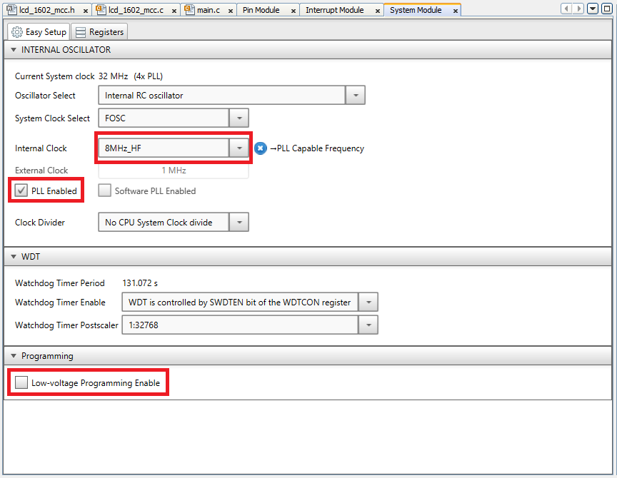
Let’s run the MCC plugin, change the MCU package, open the System Module page, set the Internal Clock as 8MHz_HF, and set the “PLL Enabled” checkbox . Also (as usual), don’t forget to remove the check from the “Low-voltage programming enable” field (Figure 6).
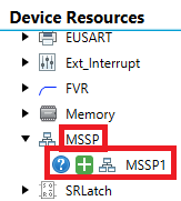
Then we need to go to the Device resources tab on the left part of the screen, expand the drop-down list “MSSP", and click on the green plus at “MSSP1” (Figure 7).
Now, let’s add the I2C library. Actually the libraries were always there but we never used them in our projects. Let’s fill this gap in our knowledge. The libraries are located at the same Device Resources tab at the very top. You need to expand the list “Libraries” and the included sublist “Foundation Services”, inside which you need to find and add the “I2CSIMPLE” position (Figure 8).
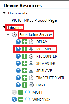
As you can see, there are some libraries, the majority of which is devoted to communication interfaces (SPIMASTER, SPISLAVE, UART, I2CSIMPLE) which we will consider in the next tutorials, and the rest provide some time-related services.
These services provide the next abstraction level over the peripheral drivers we used to know. With them you can make calls of complex operations very simple as the whole process will be hidden inside the API functions. You will see this very soon.
After adding all the parts, your Resource Management window should look like in Figure 9.
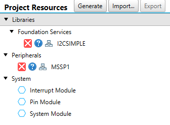
Now, let’s open the MSSP1 window and configure the corresponding module according to Figure 10.
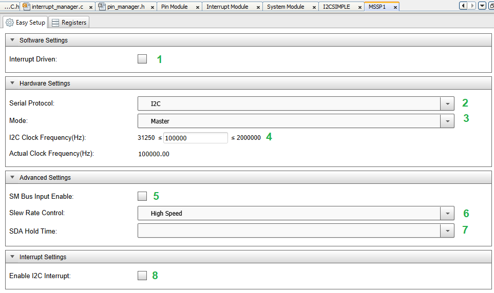
Actually, here we don’t need to change anything, as the default settings work fine for us.But let’s briefly consider the main options:
- “Interrupt Driven” allows us to perform I2C communication based on the interrupts which are called after each bus action: START, STOP, or REPEATED START issuing, receiving or sending the address, receiving or sending the data, arbitration losing. As in our program code will work consecutively, we don’t need this option but if you want you can freely set this check: anyway the operation will be hidden inside the API functions.
- “Serial Protocol”. As I mentioned, the MSSP module supports both I2C and SPI protocols. As this time we are using the first one, we leave this option unchanged as well.
- “Mode” selects the operation mode of the module: “Master” or “Slave”. Depending on this and the previous parameters the rest of the options will differ.
- “I2C Clock Frequency(Hz)” speaks for itself. It sets the frequency of the SCL clock signal. As we’re not in a rush we can leave the standard frequency of 100 kHz. Below, you can see the actual clock frequency which may differ from the value you set if the latter can’t be obtained using the current CPU frequency.
- “SM Bus Input Enable” turns on support of the SMBus which we don’t need so far.
- “Slew Rate Control” optimizes the pulses’ slew rate for high or standard communication speed. We could select the “Standard Speed” here but leaving the “High Speed” option won’t hurt either.
- “SDA Hold Time”. I frankly don’t understand this parameter because in no mode you can select anything here, so let’s just ignore it.
- “Enable I2C Interrupt”. You should set this parameter if you have set the “Interrupt Driven” option, or if you want to generate the interrupts from the I2C events.
As you can see, despite the complexity of the MSSP module, the number of the available parameters is quite limited.
Now, let’s open and configure the “I2CSIMPLE” service (Figure 11).

As you can see, the configuration of this service is extremely simple and also doesn’t need us to change anything in it.
- “Select I2C Master” selects the MSSP module which this service will use. As the PIC18F14K50 MCU has only one such module, it’s set by default and can’t be changed.
- “Select use case example to generate” allows you to select the code example of using this service. But you don’t need it because I’ll tell you everything you need to know about it.
Now, let’s switch to the Pin Module and Pin Manager and configure all required pins according to the schematic diagram (Figure 12).

Pins are configured according to the schematics diagram (Figure 4, 5). As you can see, pins RB4 and RB5 are used by the MSSP1 module and represent the SDA and SCL pins of the I2C bus, respectively. Buttons S1 (MODE) and S2 (SET) are connected to pins RA5 and RA4, respectively. We need to configure these pins as inputs with the pull-up resistors, as we don’t use the external ones. Pin RB7 is connected to the SQW output of the DS1307 chip. As the module with this RTC uses an external pull-up resistor on this pin, we don’t need to enable the internal pull-up on it. Still, we need to configure it as an input. And also we need to enable the “RA and RB port change” interrupt on it, changing the “IOC” column value from “none” to” any” for it.
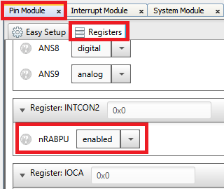
Don’t forget to enable the pull-up resistors for ports A and B (bit nRABPU of the INTCON2 register) (Figure 13). If you forget about that, the MCC will show the corresponding warning.
Finally, let’s switch to the Interrupt Module tab and make sure that the RABI interrupt is enabled (Figure 14).
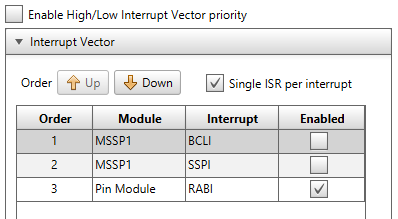
There is no need to enable the priorities of the interrupts as only one of them is active.
Now everything is configured, and we can click the “Generate” button and switch to writing code.
Program Code Description
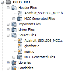
In this project, apart from those auto-generated by the MCC files, we will use three external files which represent the Adafruit SSD1306 library:
- “Adafruit_SSD1306_MCC.h” - the header file which consists of the headers of the display-related functions.
- “Adafruit_SSD1306_MCC.c” - the source file with the implementation of the display-related functions. Here we will make some changes to work with the PIC’s MSSP module.
- “glcdfont.c” contains the array in which there is a 5x7 pixels font generator for all the ASCII characters from 0 to 255.
These three files will be attached at the end of the tutorial. We will not consider them in detail as they are quite long, I will only highlight the functions in which we will make changes.
After everything, your project should look like Figure 15.
Let’s start considering the program with the SSD1306 files. As I mentioned, we will consider just the part of them which we will need to change, and which we will use in our program. But feel free to discover these files by yourself if you are curious how they work. The content of the “Adafruit_SSD1306_MCC.h” file is listed below:
#define BLACK 0
#define WHITE 1

#define SSD1306_I2C_ADDRESS   0x3C    // 011110+SA0+RW - 0x3C or 0x3D
// Address for 128x32 is 0x78
// Address for 128x32 is 0x7A (default) or 0x3C (if SA0 is grounded)
//   #define SSD1306_128_64
//   #define SSD1306_128_32
   #define SSD1306_64_32
…………………………..
extern int8_t ssd1306_getCursorY(void);
extern int8_t ssd1306_getCursorX(void);

extern  void ssd1306_init(void);
extern  void ssd1306_begin(uint8_t switchvcc/* = SSD1306_SWITCHCAPVCC*/, uint8_t i2caddr/*= SSD1306_I2C_ADDRESS*/);
extern  void ssd1306_command(uint8_t c);
extern  void ssd1306_data(uint8_t c);

extern  void ssd1306_clearDisplay(void);
extern  void ssd1306_sleep(uint8_t c);
extern  void ssd1306_invertDisplay(uint8_t i);
extern  void ssd1306_display(void);

extern  uint8_t ssd1306_getRotation(void);
extern  void
  ssd1306_setCursor(int16_t x, int16_t y),
  ssd1306_setTextColor(uint16_t c),
  ssd1306_setTextBgColor(uint16_t c, uint16_t bg),
  ssd1306_setTextSize(uint8_t s),
  ssd1306_setTextWrap(uint8_t w),
  ssd1306_setRotation(uint8_t r),
  ssd1306_drawPixel(int16_t x, int16_t y, uint16_t color),
  ssd1306_drawLine(int16_t x0, int16_t y0, int16_t x1, int16_t y1, uint16_t color),
  ssd1306_fillRect(int16_t x, int16_t y, int16_t w, int16_t h, uint16_t color),
  ssd1306_drawFastVLine(int16_t x, int16_t y, int16_t h, uint16_t color),
  ssd1306_drawFastHLine(int16_t x, int16_t y, int16_t w, uint16_t color),
  ssd1306_drawRect(int16_t x, int16_t y, int16_t w, int16_t h, uint16_t color),
  ssd1306_write(const char *c),
  ssd1306_drawChar(int16_t x, int16_t y, unsigned char c, uint16_t color,uint16_t bg, uint8_t size),
  ssd1306_drawBitmap(int16_t x, int16_t y, uint8_t *bitmap, int16_t w, int16_t h, uint16_t color),
  ssd1306_fillScreen(uint16_t color),
  ssd1306_drawCircle(int16_t x0, int16_t y0, int16_t r, uint16_t color),
  ssd1306_drawCircleHelper(int16_t x0, int16_t y0, int16_t r, uint8_t cornername, uint16_t color),
  ssd1306_fillCircle(int16_t x0, int16_t y0, int16_t r, uint16_t color),
  ssd1306_fillCircleHelper(int16_t x0, int16_t y0, int16_t r, uint8_t cornername, int16_t delta, uint16_t color),
  ssd1306_drawTriangle(int16_t x0, int16_t y0, int16_t x1, int16_t y1, int16_t x2, int16_t y2, uint16_t color),
  ssd1306_fillTriangle(int16_t x0, int16_t y0, int16_t x1, int16_t y1, int16_t x2, int16_t y2, uint16_t color),
  ssd1306_drawRoundRect(int16_t x0, int16_t y0, int16_t w, int16_t h, int16_t radius, uint16_t color),
  ssd1306_fillRoundRect(int16_t x0, int16_t y0, int16_t w, int16_t h, int16_t radius, uint16_t color);
In lines 20 and 21, there are macros BLACK and WHITE which can be used as a color argument in the display functions.
In line 23, we define the I2C address of the display. It can be either 0x3C or 0x3D depending on the connection of the SA0 pin of the driver. In some OLED display modules you can select this connection using a 0 Ohm resistor. The default address is 0x3C but if it doesn’t work for you you can try to change it to 0x3D. If you follow the non-MCC tutorials as well, you may wonder why we set the address as 0x78 there, and 0x3C here. The thing is that the I2CSIMPLE service accepts the address in the right-justified format and shifts it by itself, while if you deal with the MSSP module directly you need to do it by yourself.
In lines 42-44 we must select the resolution of the display, and only one resolution. If you select none of them, or more than one, the compiler will throw an error. In our case we have a 64 x 32 resolution so we select the SSD1306_64_32 parameter. If you have another LCD, please select your resolution as the initialization of the display differs for different resolutions.
We will skip the definitions of the display macros and variables and consider the functions which you can use to draw something on the display (lines 127-166).
- ssd1306_getCursorY and ssd1306_getCursorX return the Y and X coordinates of the current “cursor” position on the display.
- ssd1306_init should be used prior to all other display functions, as it initializes all the internal variables of the library.
- ssd1306_begin should follow the previous function. Here the proper initialization of the display driver, depending on the resolution, happens.
- ssd1306_command and ssd1306_data are used to send the command and the data to the display, respectively. We will make changes exactly in these functions as they provide the low-level communication between the MCU and the display driver.
- ssd1306_clearDisplay is used to clear the display buffer.
- ssd1306_sleep is used to switch the display mode between sleep (c = 1) and normal (c = 0) modes.
- ssd1306_invertDisplay inverts (i = 1) or returns to normal (i = 0) the view on the display.
- ssd1306_display is another function in which we will make the changes. Actually, all the drawing implemented with the functions listed below will happen only in the display buffer which is located in the RAM of the MCU, and you will not see any changes in the display until you invoke this function.
- ssd1306_getRotation returns the rotation of the display view: 0 - 0°, 1 - 90°, 2 - 180°, 3 - 270°.
- ssd1306_setCursor - sets the coordinates x and y of the “cursor”.These values should be within the resolution of the display starting from 0,0 which is the top left corner.
- ssd1306_setTextColor - sets the pen color c as WHITE or BLACK. The last option is used if you want to draw something on the filled area. Please note that this function sets the color of the pen for all drawings, not only a text.
- ssd1306_setTextBgColor - sets the pen (c) and the background (bg) color. This will affect only the elements drawn after implementation of this function, the same as for the previous function.
- ssd1306_setTextSize - sets the size of the text. The s argument is the multiplier of the text size. If it’s 1 then the text size is 5 x 7 pixels, if it’s 2 then the size is 10 x 14 pixels, and so on.
- ssd1306_setTextWrap - allows you to wrap the text and continue writing from the next line (w = 1) or disables this feature (w = 0). Please note, that it’s a text wrap, not word wrap, so it doesn’t distinguish the characters.
- ssd1306_setRotation - sets the rotation of the display (r = 0 - 0°, r = 1 - 90°, r = 2 - 180°, r =3 - 270°).
- ssd1306_drawPixel - draws a single pixel at coordinates x,y with the specified color (WHITE or BLACK).
- ssd1306_drawLine - draws a line which starts with the coordinates x0,y0 and ends with the coordinates x1,y1 with the specified color.
- ssd1306_fillRect - draws the rectangle starting with the coordinates x,y with the height h and width w with the specified color and fills it with the same color.
- ssd1306_drawFastVLine - draws a vertical line starting with the coordinates x,y with the length h with the specified color.
- ssd1306_drawFastHLine - draws a horizontal line starting with the coordinates x,y with the length w with the specified color.
- ssd1306_drawRect - draws a rectangle starting with the coordinates x,y with the height h and width w with the specified color.
- ssd1306_write - writes some string c starting with the current coordinates.
- ssd1306_drawChar - writes the single character c at the coordinates x,y with the specified pen color color, background color bg, and the text multiplier size.
- ssd1306_drawBitmap - draws a bitmap buffer bitmap starting with the coordinates x,y with the width w, height h, and the specified color.
- ssd1306_fillScreen - fills the whole display with the specified color.
- ssd1306_drawCircle - draws the circle with the center at coordinates x0,y0, radius r, and the specified color.
- ssd1306_drawCircleHelper - draws the arch of 90 - 360 degrees with the center at coordinates x0,y0, radius r, and the specified color. This is the helper function used in the ssd1306_drawRoundRect described below.
- ssd1306_fillCircle - draws the circle with the center at coordinates x0,y0, radius r, and the specified color and fills it with the same color.
- ssd1306_fillCircleHelper - draws an arch of 90 - 360 degrees with the center at coordinates x0,y0, radius r, and the specified color and fills it with the same color. This is the helper function used in the ssd1306_fillRoundRect described below.
- ssd1306_drawTriangle - draws a triangle with the summits at coordinates x0,y0; x1,y1, and x2,y2 with the specified color.
- ssd1306_fillTriangle - draws a triangle with the summits at coordinates x0,y0; x1,y1, and x2,y2 with the specified color and fills it with the same color.
- ssd1306_drawRoundRect - draws a rectangle starting with the coordinates x0,y0 with the height h and width w, and rounded corners with the radius radius with the specified color.
- ssd1306_fillRoundRect - draws a rectangle starting with the coordinates x0,y0 with the height h and width w, and rounded corners with the radius radius with the specified color and fills it with the same color.
This looks like more than enough to draw anything you want on the monochrome display. And again, all these functions draw not in the display directly but in the buffer that is located in the MCU’s RAM, and to flush this buffer to the display you need to use the ssd1306_display function.
Let’s now consider the “Adafruit_SSD1306_MCC.c” file:
#include "mcc_generated_files/mcc.h"
#include "Adafruit_SSD1306_MCC.h"
void ssd1306_command (uint8_t c)
{
  uint8_t control = 0x00;   // Co = 0, D/C = 0
  i2c_write1ByteRegister(ssd1306_i2caddr, control, c);
}

void ssd1306_data (uint8_t c)
{
  uint8_t control = 0x40;   // Co = 0, D/C = 1
  i2c_write1ByteRegister(ssd1306_i2caddr, control, c);
}

void ssd1306_begin(uint8_t vccstate, uint8_t i2caddr)
{
  ssd1306_i2caddr = i2caddr;
  __delay_ms (100);     //Wait some time to stabilize LCD voltage regulator
void ssd1306_display(void) {
  uint16_t MAX;
#ifndef SSD1306_64_32
  ssd1306_command(SSD1306_SETLOWCOLUMN | 0x0);  // low col = 0
  ssd1306_command(SSD1306_SETHIGHCOLUMN | 0x0);  // hi col = 0
  ssd1306_command(SSD1306_SETSTARTLINE | 0x0); // line #0

  MAX = SSD1306_LCDWIDTH*SSD1306_LCDHEIGHT/8;
  uint8_t buf[17];
  for (uint16_t i = 0; i < MAX; ) {
    buf[0] = 0x40;              	//First byte is the "data" identifier
    for (uint8_t x = 0; x < 16; x ++) {
        buf[x + 1] = ssd1306_buffer[i];  //Fill the buffer
        i++;
    }
    i2c_writeNBytes(ssd1306_i2caddr, buf, 17);
  }
# else //SD1306_64_32
  MAX = SSD1306_LCDWIDTH*SSD1306_LCDHEIGHT/8;
  uint8_t buf[65];
  for (uint16_t i = 0; i < MAX; ) {
    buf[0] = 0x40;              	//First byte is the "data" identifier
    for (uint8_t x = 0; x < 64; x ++) {
        buf[x + 1] = ssd1306_buffer[i];  //Fill the buffer
        i++;
    }
    i2c_writeNBytes(ssd1306_i2caddr, buf, 65);
  }
#endif
}
Functions ssd1306_command (lines 39-43) and ssd1306_data (line 45-49) are actually the same except for the control byte which is sent prior to the command/data byte c. For commands, this byte is 0x00 (line 41) and for data, it is 0x40 (line 47). Moreover, the ssd1306_data function is never used in this library, and I believe it’s left as a legacy or in case you want to send some data to the display without the display buffer. So we will consider only the ssd1306_command function. It’s actually quite simple and consists of only one function i2c_write1ByteRegister.
Actually, if you look at the file “MCC Generated Files/drivers/i2c_simple_master.h”, you will find that it consists of just 7 functions provided by the I2CSIMPLE service:
uint8_t i2c_read1ByteRegister(i2c1_address_t address, uint8_t reg);
uint16_t i2c_read2ByteRegister(i2c1_address_t address, uint8_t reg);
void i2c_write1ByteRegister(i2c1_address_t address, uint8_t reg, uint8_t data);
void i2c_write2ByteRegister(i2c1_address_t address, uint8_t reg, uint16_t data);
void i2c_writeNBytes(i2c1_address_t address, void* data, size_t len);
void i2c_readDataBlock(i2c1_address_t address, uint8_t reg, void *data, size_t len);
void i2c_readNBytes(i2c1_address_t address, void *data, size_t len);
These functions cover the most widespread cases of using the I2C Master interface.
i2c_read1ByteRegister and i2c_read2ByteRegister functions allow reading either an 8-bit or 16-bit register from the specified register reg from the device with the specified I2C address.
i2c_write1ByteRegister and i2c_write2ByteRegister allow writing either 8-bit or 16-bit data into the specified register of the specified device.
i2c_writeNBytes allows you to write some buffer data with the length len to the specified device. Please pay attention that the type of the buffer is void so you can transfer any data using this function.
i2c_readDataBlock allows you to read some buffer data with the length len from the device registers starting with the specified address reg.
void i2c_readNBytes is similar to the previous one but here you don’t specify the address of the register to read from, and just read some data.
So, let’s return to our code now. In ssd1306_command and ssd1306_data functions we need to write two bytes to the SSD1306 driver - control byte and the command or data itself (argument c of the functions). We can do this with the function i2c_write1ByteRegister if we consider the control byte as the register address reg and the c argument as the data byte. We can make this assumption as the i2c_write1ByteRegister function just consecutively sends the reg and the data bytes to the specified device.
In the function ssd1306_begin we add the 100 ms delay (line 54) to wait while the display’s voltage regulator has stabilized. If we start initialization right after power up, the driver may not be ready yet, and the display will not be initialized properly.
In lines 414-443, there is the ssd1306_display function which is responsible for sending the display buffer from the RAM memory of the MCU into the display itself. The buffer is organized as a set of bytes, each bit of which represents the state of some pixel on the display. If this bit is 1 then the pixel is turned on, otherwise it’s turned off. These bytes are sent to the display row-wise. So you first fill the first eight rows (each byte holds information about eight bits), then you fill the next eight rows and so on and so forth. As the resolution of our display is 64 x 32 pixels we will need to send 64 x (32 / 8) = 256 bytes in total. Actually, this value is assigned to the MAX variable (defined in line 415 and assigned in lines 421 and 432).
I will tell you honestly, I don’t know exactly why this function is implemented this way, I just took it from the source like this. According to the data sheet of the SSD1306 driver it might be implemented more simply but probably there were some reasons to write it exactly like this. Or maybe the first developer just wrote it and thought “OK, this works, so let’s leave it.” I can sympathize.
So, as you can see, this function is split into two parts. First one (lines 416 - 430) is dedicated to the displays with the 128 x 64 and 128 x 32 resolutions, and the second one (lines 431-442) works with the resolution of 64 x 32. The parts are distinguished by the #ifndef-#else-#endif directives of the compiler which we already used in the PIC10F200 tutorials. They allow us to perform a so-called conditional compilation. #ifndef means “if not defined”, so this part of the code will be implemented if the following macro is not defined (in our case it’s SSD1306_64_32). But we have specifically defined this macro in line 44 of the “Adafruit_SSD1306_MCC.h” file, so lines 416-430 will be ignored, and the part between the #else and the #endif directives will be compiled. So let’s consider it as the upper part is quite similar, there are just some extra commands before sending the data (lines 417-419) and the data is sent with the smaller chunks.
So, in line 432 we assign the value SSD1306_LCDWIDTH*SSD1306_LCDHEIGHT/8 to the MAX variable for the reasons I’ve already mentioned.
In line 433, we declare the buf array of 65 bytes which is the temporary buffer to send the chunks of the data to the display. In the next line we start the loop to send all MAX bytes to the display. Inside this loop (lines 435-440) we do the following: assign value 0x40 to the first element of the buf array (line 450) to indicate that the following bytes should be treated as display data, not commands. Then we fill the rest of the buf array with the 64 bytes (the whole row) of the ssd1306_buffer (lines 436-439). Finally, in line 440, we send the buf array to the display using the i2c_writeNBytes function. Then in the same way we send the rest of the ssd1306_buffer with the 64 bytes chunk.
Again, I don’t know why it’s done like this, there should not be any obstacles to send the whole display buffer at once. You can try this by yourself as homework, by the way.
The “glcdfont.c” only consists of the constant array font, which is used to generate the ASCII characters to write on display. Actually, there is nothing to consider there in detail, so let’s just skip it.
And now let’s finally consider the “main.c” file in which the main logic of our program is implemented.
#include "mcc_generated_files/mcc.h"
#include "Adafruit_SSD1306_MCC.h"

#define DS1307_ADDR	0x68 	//I2C address of the DS1307 chip

uint8_t clock_data[7];      	//Array to read the data from the RTC
uint8_t update_clock_flag;  	//Indicates that we need to update the time
uint8_t mode;               	//Clock mode: 0 - normal, 1 - set hour, 2 - set minute, 3 - set day, 4 - set month, 5 - set year

void clock_write (uint8_t reg, uint8_t data)
{
  i2c_write1ByteRegister(DS1307_ADDR, reg, data); //Write the data into the DS1307 register
}

void clock_read (uint8_t *data)
{
  i2c_readDataBlock(DS1307_ADDR, 0x00, data, 7); //Read seven bytes from DS1307 starting from the register 0x00
}

void write_date_time (void)
{
  char s[11];
  ssd1306_clearDisplay(); 	//Clear the display buffer
  ssd1306_setCursor(8,0); 	//Set cursor to the first line
  sprintf(s,"%02x:%02x:%02x",clock_data[2], clock_data[1], clock_data[0] & 0x7F); //Form the time string
  ssd1306_write(s);       	//Write the string to the OLED
  ssd1306_setCursor(2,10);	//Set cursor to the second line
  sprintf(s,"%02x.%02x.20%02x",clock_data[4], clock_data[5], clock_data[6]); //Form the date string
  ssd1306_write(s);       	//Write the string to the OLED
  switch (mode)           	//Check the clock mode
  {
    case 1: ssd1306_drawFastHLine(8, 8, 12, WHITE); break; //If "set hour" then draw the line under the hour
    case 2: ssd1306_drawFastHLine(26, 8, 12, WHITE); break;//If "set minute" then draw the line under the minute
    case 3: ssd1306_drawFastHLine(2, 18, 12, WHITE); break;//If "set day" then draw the line under the day
    case 4: ssd1306_drawFastHLine(20, 18, 12, WHITE); break;//If "set month" then draw the line under the month
    case 5: ssd1306_drawFastHLine(38, 18, 24, WHITE); break;//If "set year" then draw the line under the year
  }
  ssd1306_display();      	//Send the display buffer to the OLED
}

void pin_change_handler (void)    	//RA and RB pin change nterrupt handler
{
  update_clock_flag = 1;        	//Set the update_clock_flag variable
}

void main(void)
{
  // Initialize the device
  SYSTEM_Initialize();
  IOCB7_SetInterruptHandler(pin_change_handler); //Set the interrupt handler function
  // Enable the Global Interrupts
  INTERRUPT_GlobalInterruptEnable();

  ssd1306_init();     	//Initialize the display variables
  ssd1306_begin(SSD1306_SWITCHCAPVCC, SSD1306_I2C_ADDRESS); //Initialize the display itself
  ssd1306_setTextColor(WHITE);  //Set text color visible
  ssd1306_sleep(0);       	//Wake up the display
  ssd1306_setTextSize(1); 	//Set text size

  clock_write(0x00, 0x00);	//Start the clock oscillator
  clock_write(0x07, 0x10);	//Enable the SWQ output with 1 second period

  mode = 0;           	//Normal mode

  while (1)
  {
    if (update_clock_flag)  	//If we received the signal from the SQW output
    {
      update_clock_flag = 0;  //Reset the flag
      clock_read(clock_data); //Read the clock data
      write_date_time();  	//And update the LCD
    }

      if (MODE_BUTTON_GetValue() == LOW) //If the Mode button is pressed
      {
        __delay_ms(20);     //Then perform the debounce delay
        if (MODE_BUTTON_GetValue() == LOW) //If after the delay button is still pressed
        {
          while (MODE_BUTTON_GetValue() == LOW); //Then wait while button is pressed
          __delay_ms(20);  //After button has been released, perform another delay
          if (MODE_BUTTON_GetValue() == HIGH) //If the button is released after the delay
          {
            mode ++;       	//Increment the mode variable
            if (mode > 5)  	//If it's greater than 5
            {
              mode = 0;   	//Then reset it,
              for (uint8_t i = 1; i < 7; i ++)//And write the new date and time into RTC
                clock_write(i, clock_data[i]);
              clock_write(0x00, 0x00);	//start the clock oscillator
            }
            if (mode > 0)   	//If mode is not normal
            {
              clock_write(0x00, 0x80);	//Stop the clock oscillator
            }
            write_date_time();  //Update the display with the new values
          }
       }
    }

    if (SET_BUTTON_GetValue() == LOW) //If the Set button is pressed
    {
      __delay_ms(20);     //Then perform the debounce delay
      if (SET_BUTTON_GetValue() == LOW) //If after the delay button is still pressed
     {
     while (SET_BUTTON_GetValue() == LOW); //Then wait while button is pressed
     __delay_ms(20);  //After button has been released, perform another delay
     if (SET_BUTTON_GetValue() == HIGH) //If the button is released after the delay
     {
       switch (mode)   	//Check the mode
       {
         case 1:     	//"Set hour" mode
           clock_data[2]++; //Increment the hours value
           if ((clock_data[2] & 0x0F) == 0x0A) //If the last character becomes 0x0A
             clock_data[2] += 6; //Then we add 6 to the hours value as it is in the BCD format
           if (clock_data[2] >= 0x24) //If the hours value is greater or equal than 24
             clock_data[2] = 0;  //Then set it as 0
           break;
         case 2:     	//"Set minute" mode
           clock_data[1]++; //Increment the minutes value
           if ((clock_data[1] & 0x0F) == 0x0A) //If the last character becomes 0x0A
             clock_data[1] += 6; //Then we add 6 to the minutes value as it is in the BCD format
           if (clock_data[1] >= 0x60) //If the minutes value is greater or equal than 60
             clock_data[1] = 0; //Then set it as 0
           break;
         case 3:     	//"Set day" mode
           clock_data[4]++; //Increment the days value
           if ((clock_data[4] & 0x0F) == 0x0A) //If the last character becomes 0x0A
             clock_data[4] += 6; //Then we add 6 to the days value as it is in the BCD format
           if (clock_data[4] >= 0x32) //If the days value is greater or equal than 32
             clock_data[4] = 1; //Then set it as 1
           break;
         case 4:     	//"Set month" mode
           clock_data[5]++; //Increment the months value
           if ((clock_data[5] & 0x0F) == 0x0A) //If the last character becomes 0x0A
             clock_data[5] += 6; //Then we add 6 to the months value as it is in the BCD format
           if (clock_data[5] >= 0x13) //If the months value is greater or equal than 13
             clock_data[5] = 1; //Then set it as 1
           break;
         case 5:     	//"Set year" mode
           clock_data[6]++; //Increment the years value
           if ((clock_data[6] & 0x0F) == 0x0A) //If the last character becomes 0x0A
             clock_data[6] += 6; //Then we add 6 to the years value as it is in the BCD format
           if (clock_data[6] >= 0x99) //If the years value is greater or equal than 99
             clock_data[6] = 0; //Then set it as 0
           break;
         }
         write_date_time();  //Update the display with the new values
       }
     }
   }
  }
}
The programs become larger and larger but what can we do? We grow up, mature, and don’t fit in 100 lines anymore.
In line 1, we, as usual, include the “mcc_generated_files/mcc.h” file to use the MCC-generated variables, functions, and macros. In line 2, we include the “Adafruit_SSD1306_MCC.h” file, which consists of the display-related functions we have considered above.
in line 4, we define the macro DS1307_ADDR and assign the value 0x68 to it. This is the right-justified I2C address of the DS1307 RTC chip.
In lines 6-8 we declare some global variables:
- clock_data is the array of seven elements to read the content of the registers 0x00 - 0x06 of the DS1307 chip which represent the time and date from second to year (see table 1).
- update_clock_flag is the flag that indicates that the time and date needs to be updated. This flag is set by the SQW signal from the DS1307 RTC.
- mode is the variable that sets the clock operation mode. If it is 0, it’s a normal mode when the time is read from RTC and shown on the OLED display. Modes 1 to 5 represent the setting of some time or date parameter. We will talk about them later.
As we already got used to, let’s first skip the user’s functions and consider the main function of the program which is located in lines 46-152.
The initialization part occupies lines 48-63. In line 49, there is the MCC-generated function SYSTEM_Initialize which initializes all the hardware modules of the MCU.
In line 50, we invoke the IOCB7_SetInterruptHandler function which sets the callback function which will be called when the RA and RB port change interrupt occurs (in our case when the SQW signal from the RTC chip will change its state). This callback function is called pin_change_handler and is described in lines 41-44.
In line 52 we enable global interrupts.
In lines 54-58, we initialize the OLED display. I recommend using this exact sequence in any future projects related to this display.
First, we need to invoke the ssd1306_init function (line 54) to initialize the internal variables of the library. Second, we invoke the ssd1306_begin function (line 55) which has two arguments: SSD1306_SWITCHCAPVCC which sets the voltage source of the OLED matrix as the internally generated one by the SSD1306 driver, and SSD1306_I2C_ADDRESS which is the I2C address of the display. The function ssd1306_setTextColor with the argument WHITE (line 56) sets the text color as white (or whatever color the display has). Without it, all the text and other drawing primitives will remain invisible. Invocation of the ssd1306_sleep function with the parameter ‘0’ (line 57) wakes up the display. If you want to turn it off to save the power, just call this function with the parameter ‘1’. Finally, the ssd1306_setTextSize function (line 58) sets the minimal text size of 6 x 8 pixels. The larger size will make the text more visible but unfortunately, we will not fit all the information in the display in this case.
In lines 60, 61, we initialize the RTC with the function clock_write which we will discover later. This function has two arguments - the register address according to Table 1, and the value to write into it. So we first write 0x00 into the 0x00 (Seconds) register to clear the CH bit and start the RTC. And then we write 0x10 into the 0x07 (Control) register to set the bit OUT and clear all other bits. This will lead to forming the 1 Hz pulses on the SQW pin of the RTC (see tables 1 and 2).
In line 63, we clear the mode variable to start operation in the normal mode. And with this, the initialization part is over.
In lines 65-151, there is the main loop of the program, which is long but consists of some similar blocks.
First, we check if the update_clock_flag variable is set (line 67). It becomes 1 when the SQW signal changes its state and the RA and RB port change interrupt is triggered. This interrupt is processed in the callback function pin_change_handler I’ve already mentioned, and the only thing we do inside it is setting the update_clock_flag as 1 (line 43). As the frequency of the SQW signal is 1 Hz, this will happen twice a second.
So, when the update_clock_flag variable is set, we first clear it (line 69), then read the registers 0x00-0x06 from the RTC using the function clock_read (line 70) and send the new date and time to the display with the function write_date_time (line 71). Both these functions will be considered later.
In lines 74-98 there is a standard blocking processing of the S1 button press. We considered it several times in previous tutorials, so we will consider only the payload of it (lines 83-95). This function changes the mode of operation of the clock in a circle allowing us to update, consequently, hours, minutes, days, months and years, and return to the normal mode. So, first it increments the mode variable (line 83) which can take the values from 0 to 5. If, after incrementing, it becomes greater than 5 (line 84) we assign 0 to it (line 86) and return to the normal operation mode. To do this, we write the new values into the Minutes-Year register (lines 87, 88) and start the RTC counting again by writing 0 into the Seconds register (line 89).
If the operation mode differs from the normal (mode > 0, line 91) then we stop the oscillation of the RTC by setting the bit CH in the Seconds register (line 93) to prevent the unintended change of the date and time by the clock itself.
In line 95 we invoke the write_date_time function to update the display, as each mode changing highlights the value that is currently being changed.
In lines 100-151 we process the S2 button. The payload of this part is located at lines 109-147. This button is used to increment the time or date value (hour, minute, day, month, year) which is selected by the S1 button. Even though this part is quite long, it consists of very similar code chunks. Let’s consider incrementing the hours (lines 111-117). Changing the hours value corresponds to mode = 1 which we check in line 111.
The clock_data array consists of the time and date values, and the number of the element of the array corresponds to the number of the register of the DS1307 RTC (see table 1). As we want to change the hours value, we need to operate with the second element of the clock_data array. So, in line 112 we increment it. As the data stored in the array is in the BCD (binary-coded decimal) format, we need to do some tricks to increment it correctly. If you don’t know anything about the BCD format, I recommend you to get acquainted with it here.
I will briefly remind you what it is if you don’t want to read another big tutorial. So in BCD format, unlike the regular binary format, each nibble (four bits) of the byte represents the decimal digit from 0 to 9. Even though each nibble can have the maximum value of 15, the upper six bit combinations are not used which makes this format less compact than binary. But what’s its advantage? It simplifies splitting the number into digits. If you remember, if we want to split a regular 2-digit number, we need to divide it by 10 to get the number of tens, and take a modulo of division by 10 to get the number of ones. Even though in C this operation is quite simple, in fact, the PIC MCU doesn’t have an instruction to implement division, so it will take a while for it to calculate the value. In the case of the BCD format, we just need to implement the AND operation between the value and the 0xF0 mask to get the number of tens, and the same AND operation between the value and the 0x0F mask to get the number of ones which, from the MCU’s perspective, is much simpler.
The BCD format is stored as a hexadecimal number which looks like a decimal number which we want to display. For example if we want to have the number 25 in BCD format, it will be stored as 0x25. So this presents the problem of what happens when we increment a number that ends with 9. As it is stored in the hexadecimal format, after incrementing, it will become 0xA which corresponds to the decimal 10. And we need to have the value of 0x10. So if the number ends with 9 after its incrementing we need to add another 6 as 0x10 - 0x0A = 6. This is what we do in lines 113-114. In line 113, we check, if after the incrementing we get a number that ends with 0x0A. If it is so, then we add the number 6 to the clock_data value (line 114) to get the correct BCD number.
In line 115, we check if the hour's value is greater or equal than 24 (see, it’s still in BCD format, like 0x24). If it is so, we assign the 0 to the hours (line 116).
All other parameters are treated in the same way: minutes (lines 118-124), days (lines 125-131), months (lines 132-138), and years (lines 139-145). The only differences are the maximum values and the values to which these parameters are reset (for example, days and months start with 1, not with 0).
After any change of any parameter, we update the display with the function write_date_time (line 147). As the clock is stopped when we set it up, the SQW signal is not generated either, so updating the display is implemented only here.
And that’s everything about the main function. Let’s now return to line 10 and consider the rest of functions.
The clock_write function (lines 10-13), as it was mentioned before, is used to send the byte data into the register reg of the DS1307 RTC chip. As follows from its description, it exactly repeats the i2c_write1ByteRegister function, which is the only function called in the clock_write function (line 12). We could eliminate this function entirely but, with it, the code is more readable.
The clock_read function (lines 15-18), as follows from its name, is used to read the data from the DS1307 RTC. This function, unlike the previous one, reads all the registers from 0x00 to 0x06 and stores them into the data array. For this purpose the i2c_readDataBlock function (line 17) serves us well.
The write_date_time function (lines 20-39) is responsible for sending the date and time values to the OLED display.
In line 22, we declare the s array to form the time and date strings to send to the display.
In line 23, we clear the display, then set the cursor on the position [8, 0] (line 24). In this line of the display we will show the time in format hh:mm:ss. As you can see, this string consists of eight characters. As each character uses 6 pixels and the display width is 64 pixels, to put the text in the middle of it, we need to make an offset for (64 - 6 x 8) / 2 = 8 pixels, which we do in line 24.
Now, some notes about forming the string (line 25). We use the standard C function sprintf for this. Its first argument is the pointer to the char array into which the string will be stored. The second argument is the string format. In our case it’s:
"%02x:%02x:%02x"
The % character means that “at this place” will be replaced with some value (number, character or string). The type of the parameter is set by the letter after it. In our case letter ‘x’ means hexadecimal number (I hope you still remember that we are dealing with the numbers in BCD format). The digits between ‘%’ and ‘x’ are the format modifiers. Number ‘2’ means that we want the number to always use 2 positions, and the preceding number ‘0’ means that if the number is smaller than 10, we need to fill the upper positions with zeros. Let me show you some examples of how these modifiers work.
sprintf format | Formed string |
“%02x:%02x:%02x” | 10:05:03 |
“%2x:%2x:%2x” | 10: 5: 3 |
“%x:%x:%x” | 10:5:3 |
As you can see, the first option suits the best for displaying the time.
The rest of the parameters are the values that should be put instead of the ‘%x’ in the string format, and they should be written in the same order, and their amount should match the amount of ‘%’. We write clock_data[2] for hours, clock_data[1] for minutes and clock_data[0] for seconds. Please note, that for the seconds value we implement the AND operation between the clock_data[0] and the 0x7F. This is because bit#7 of the Seconds register is CH and can be set as 1 (see table 1).
In line 26, we put the string s into the display buffer with the ssd1306_write function.
In line 27, we set the cursor on position [2, 10]. In this line we will output the date in format DD.MM.YYYY, which occupies 10 characters, so the offset should be (64 - 10 x 6) / 2 = 2. The vertical offset is 10 even though the character width is 8 pixels. But we are going to use the underscore to indicate that some parameter is being changed now (when the mode is greater than 0), so we need some room for the underscore in our vertical height.
In line 28, we form another string with the format:
"%02x.%02x.20%02x"
Here the ‘20’ number between the last ‘%02x’ is just ‘20’, and represents the first two digits of the year.
In line 29, we put the updated s string into the display buffer.
In lines 30-37 we draw the horizontal line under the value which we are changing at the moment using the ssd1306_drawFastHLine function. For example, if mode is 1, this means that we change the Hours value, so we draw the line underneath it (line 32), and so on.
When all the drawings are done, we invoke the ssd1306_display function to flush the display buffer into the display itself (line 38).
And with this we are finally done with the program code. This time it was really long, considering the number of files we had to describe.
Testing of the Real Time Clock (RTC)
Let’s now assemble the device according to Figure 4 or Figure 5, compile and build the project and flash it into the PIC18F14K50 MCU. If everything is assembled and programmed correctly, you should see the following text on your display (Figure 16).
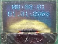
My display is a bit fried, as you can see. This happened when I soldered one wrong capacitor in the charge-pump circuit of the display driver. The lower part of the matrix is now burned but the upper one still works well. And this is a warning to those who decide to assemble the Universal board themselves - be careful with the parts you solder.
When you press the S1 button, the underscore appears under the hour. The next button press moves the underscore to the minutes. Pressing the S2 button will change the highlighted parameter (Figure 17).
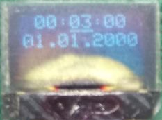
Holding the S1 and S2 buttons you can set the current date and time. After you press the S1 button after setting the year, the clock will return to the normal state, and the seconds will start to change automatically.
And that’s finally all! In this tutorial, we have learnt the MSSP module of the PIC18F14K50 MCU in I2C mode. We have connected the OLED display and the RTC to the MCU using the I2C bus and implemented a simple clock and calendar.
As homework, I suggest you improve the setting of the clock, so while the button S2 is kept pressed, the corresponding value is changed 3 times per second.
Project Files

Get the latest tools and tutorials, fresh from the toaster.

