Porting the Arduino OLED Library to the Renesas RA Family | Renesas RA - 8
Published
Hello! Today we continue the displays topic but this time we will use a more advanced monochrome OLED display with a 128x64 pixels resolution. Such displays are very widespread and can be purchased from eBay or Aliexpress for about $1.5 - $2.5 USD. The appearance of the display module is shown in Figure 1.
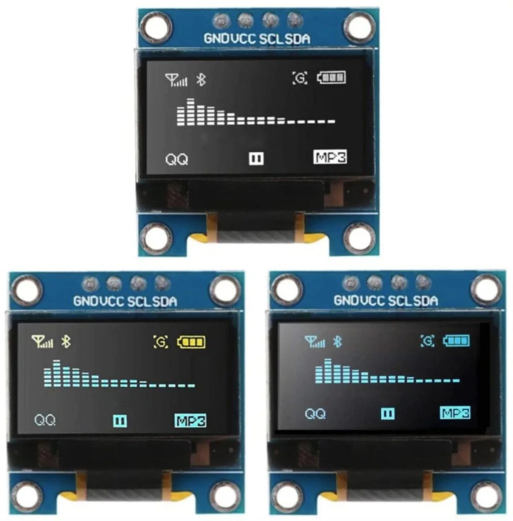
The most widespread ones have white, blue or blue/yellow color (don’t delude yourself with the last option: it has 16 yellow lines and 48 blue lines, so it is not a true two-color display). As you can see in Figure 1 the LCD has just four pins to connect:
- GND - negative power pin
- VCC - positive power pin. Even though the display driver requires 3.3 - 3.6 V to operate, you can apply up to 5V to this pin, as there is the LDO voltage regulator on board.
- SCL and SDA - clock and data pins of the I2C interface.
These displays have the SSD1306 driver which is quite advanced in comparison to the HD44780 driver so its description would take many pages. Thus you can read the data sheet of this driver if you want to know more: https://cdn-shop.adafruit.com/datasheets/SSD1306.pdf.
In this tutorial I want to suggest a totally new approach to programming which is quite useful sometimes and can save you a lot of time. This is porting an existing library instead of writing your own from scratch. For advanced peripherals (to which the OLED display belongs) developing your own driver can take several days or even weeks so this is impractical.
As a basis for the current project we will use the Adafruit SSD1306 library written for the Arduino platform: https://github.com/adafruit/Adafruit_SSD1306. My choice fell on this library because it’s quite powerful and has a lot of drawing possibilities, also Adafruit is a well-known company, so one can trust the code they write. So in this tutorial I’ll show you how to download, include in the project, adjust the code, and use this library. In the same way you can port any Arduino library to the RA MCUs.
Schematic Diagram of the Circuit
In Figure 2 you can see the connection diagram of the OLED display to the EK-RA2A1 board.
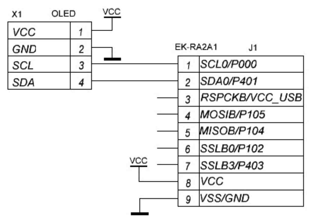
As you can see, in comparison to previous schematics, this one is much simpler. Here we use the J1 connector of the development board instead of the J2 we used to connect the 1602 LCD. Also here we don’t need any additional parts: the OLED module may be freely supplied with 3.3V. Also it has on-board pull-up resistors on SCL and SDA lines, so you don’t need to install external ones. We just connect four wires - and that’s it.
As for the I2C support in the RA family, this exact MCU has two dedicated I2C modules called IIC0 and IIC1. Also, it has three Serial Communication Interfaces (SCI) called SCI0, SCI1, and for some reason, SCI9. As follows from Figure 2 we connected our display to the IIC0 module (because pins are called SCL0 and SDA0), so we need to configure it prior to porting the library.
MCU Configuration
Let’s first create a new RA project in the way I described in tutorial 2 with one small exception. In the “Device and Tools Selection” step we need to select the C++ language instead of C (Figure 3).
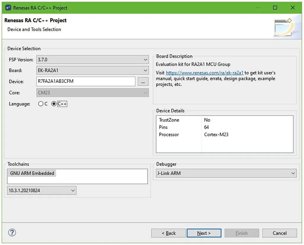
This is needed because the Adafruit library (like almost all Arduino libraries) is written in C++.
For this project you need to select the template “Bare Metal - Minimal”.
In the “FSP Configuration” window we need to switch to the “Pins” tab, scroll down to the “Peripherals” list, find the “Connectivity:IIC” sublist, and select the “IIC0” line. Then make the changes presented in Figure 4.
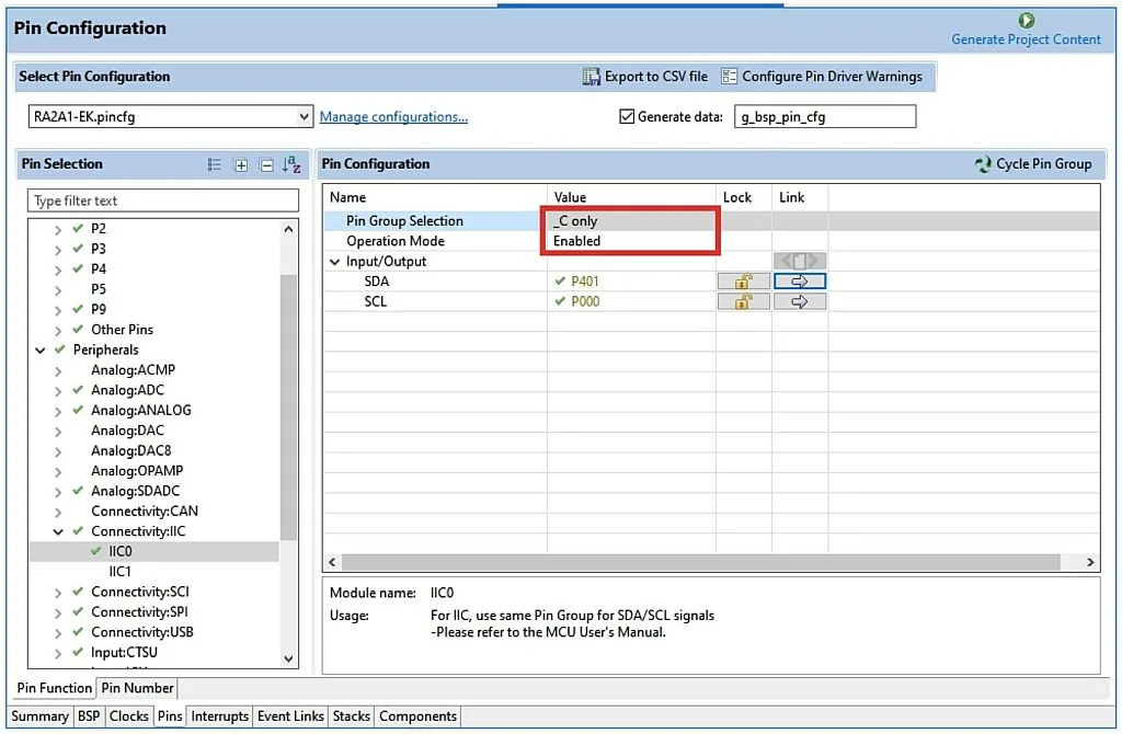
We need to make just two changes here:
- Change “Pin Group Selection” field to “_C only”. This is needed because the IIC0 module has three pairs of SCL/SDA pins which are called group A, group B, and group C. The P000 and P401 pins to which the OLED is connected (see Figure 2) are the group C, that’s why we need to select it.
- Change “Operation Mode” to “Enabled” to internally connect the P000 and P401 pins to the IIC0 module.
Make sure that the SDA pin is now P401, and SCL pin is P000.
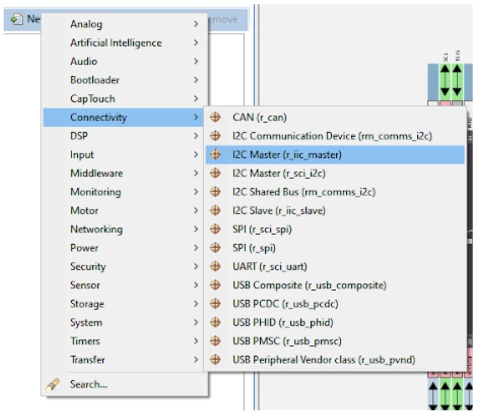
That’s all about the pins configuration, now we need to add the corresponding stack. So switch to the “Stacks” tab, click on the “New Stack >” button, expand the “Connectivity” list and select the “I2C Master (r_iic_master)” line (Figure 5).
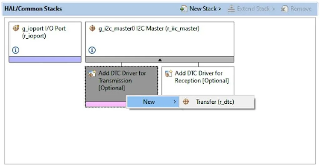
The next step is optional and will not affect anything else further. I mean adding the DTC Drivers for data transmission and reception. As I mentioned in tutorial 6, it’s always a good idea to use the DTC to reduce the load of the CPU. So if you want to use it, you need to click on the “Add DTC Driver for Transmission”, you will see the pop-up menu “New >”. Open it and select the “Transfer (r_dtc)” module (Figure 6).
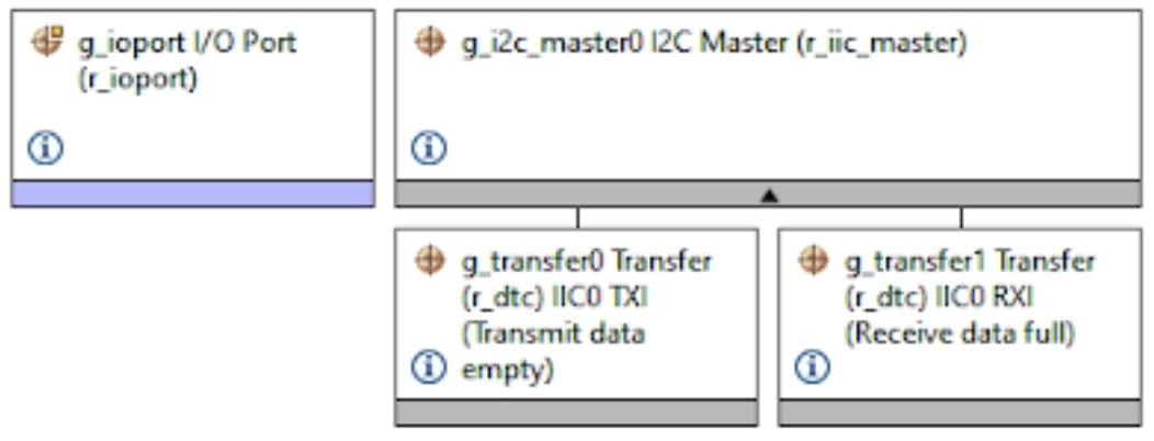
Then do the same for the “Add DTC driver for Reception” block. After that you will have the following Stacks view (Figure 7).
We don’t need to change the DTC modules settings as they are all already configured and locked. But we need to configure the I2C module. So click on the “g_i2c_master0 I2C Master (r_iic_master)” block and change its properties according to Figure 8.
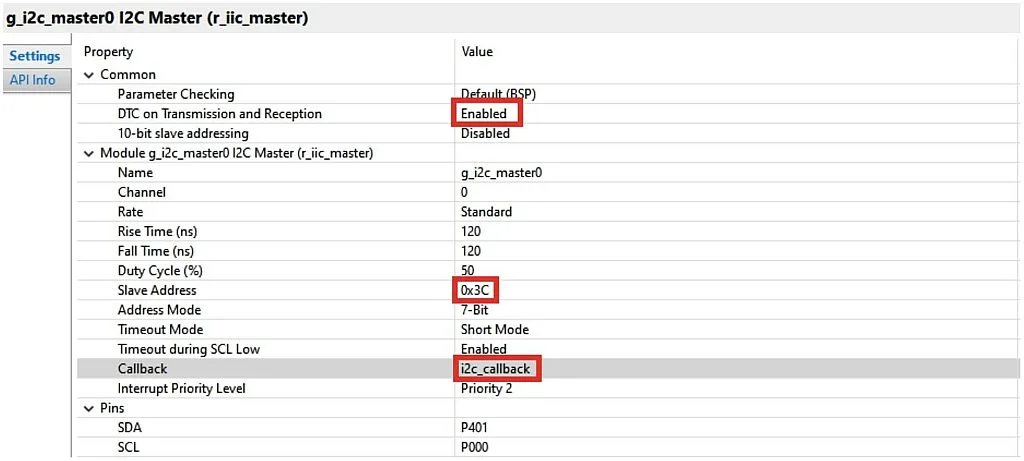
- As long as we added the DCT modules to the IIC0 stack, we need to enable it in the “DTC on Transmission and Reception” field.
- “10-bit slave addressing” enables the 10-bit I2C addressing mode support which we don’t need in the current case, so we leave is as “Disabled”.
- The “Name” field may be left unchanged or you can change it to your own one.
- The “Channel” field should remain 0, as we use the IIC0 module.
- The “Rate” field sets the I2C communication speed: “Standard” is 100 kHz, “Fast-mode” is 400 kHz, “Fast-mode plus” is 1 MHz. As we’re not going to display the dynamic images, standard speed works good for us.
- “Rise Time”, “Fall Time” and “Duty Cycle” fields set the parameters of the pulses, we will better not change them unless we know exactly that we have some different values.
- The “Slave Address” field is the address of the slave device. In our case it’s the OLED display which according to the data sheet can have the address 0x3C or 0x3D depending on the jumper position on the display module. The default value is 0x3C so we write it here. Some curious readers may notice that on the OLED module board there are other addresses: 0x78 or 0x7A. To understand why it is so, we need to recall that an I2C address consists of 7 bits of the device address, and the LSB is the read/write bit. So some MCUs adjust the device address to the left, leaving the MSB free, the other MCUs adjust the device address to the right, leaving the LSB free. If we convert the values 0x3C and 0x78 into the binary system, we will see the following: 0x3C = 0b00111100, 0x78 = 0b01111000. So it’s the same address but with different adjustments. The same with values 0x3D and 0x7A, you can check this by yourself.
- The “Address Mode” field sets the 7-bit or 10-bit addressing mode. As I mentioned before, we need to leave the 7-bit mode.
- The “Timeout Mode” field selects the timeout mode to detect bus hanging. It can be short or long.
- The “Timeout during SCL Low” field enables the timeout event if the SCL line is held low by the slave for the time specified in the “Timeout Mode” field.
- The “Callback” field is the custom name of the callback function which is invoked from the IIC0 module interrupt subroutine. We need to use the callback to detect the transmission end event, so we need to give it some name instead of NULL. I selected the simple “i2c_callback” name but you may call it whatever you want.
- The “Interrupt Priority Level” can be left as is because we don’t use any other interrupts here.
- The “SCL” and “SDA” pins should correspond to real pins to which the I2C bus is connected. In our case there are pins P401 and P000, respectively.
Now the IIC0 module is totally configured. There is only one thing left to do. We need to increase the heap size to 0x1000 in the same way as I told in the tutorial 7.
There are all settings we need to do using the FSP Configurator, so now we can click on the “Generate Project Content” button, and proceed to porting the Arduino library.
Porting the Adafruit SSD1306 library
Now let’s open the GitHub Adafruit page https://github.com/adafruit/Adafruit_SSD1306 and click on the button “Code” then select the option “Download ZIP” (Figure 9).
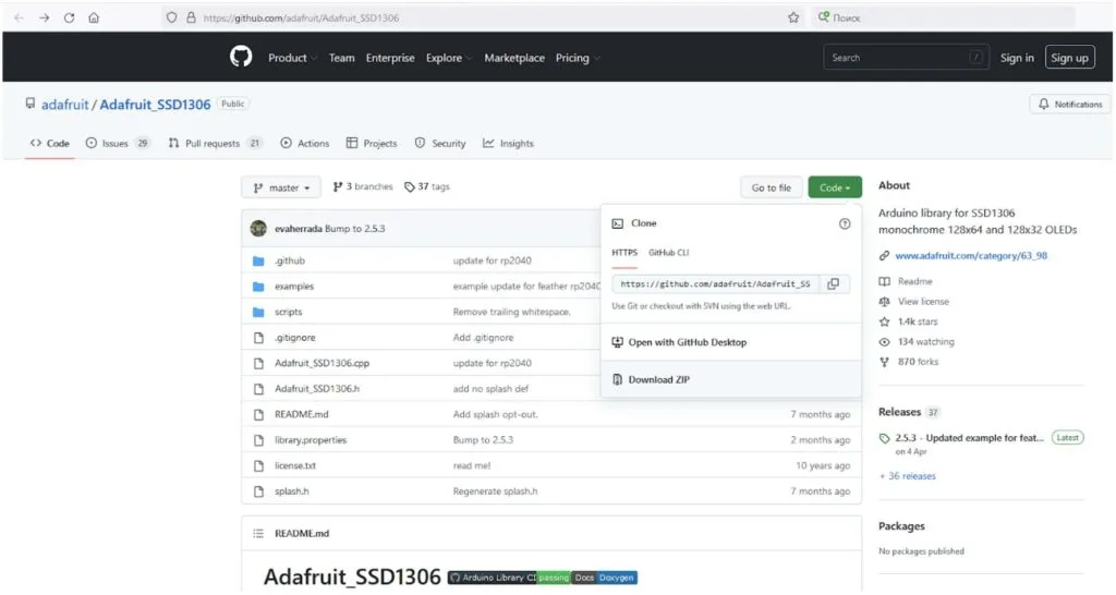
This library is based on the Adafruit GFX library which we also need to download from this link: https://github.com/adafruit/Adafruit-GFX-Library. Current versions of the libraries are 2.5.3 for SSD1306, and 1.11.1 for GFX.
Now, we have two archives: “Adafruit_SSD1306-master.zip” and “Adafruit-GFX-Library-master.zip”. We need to unpack them into the “src” folder of our project. After that we will see the following in the Project Explorer (Figure 10).
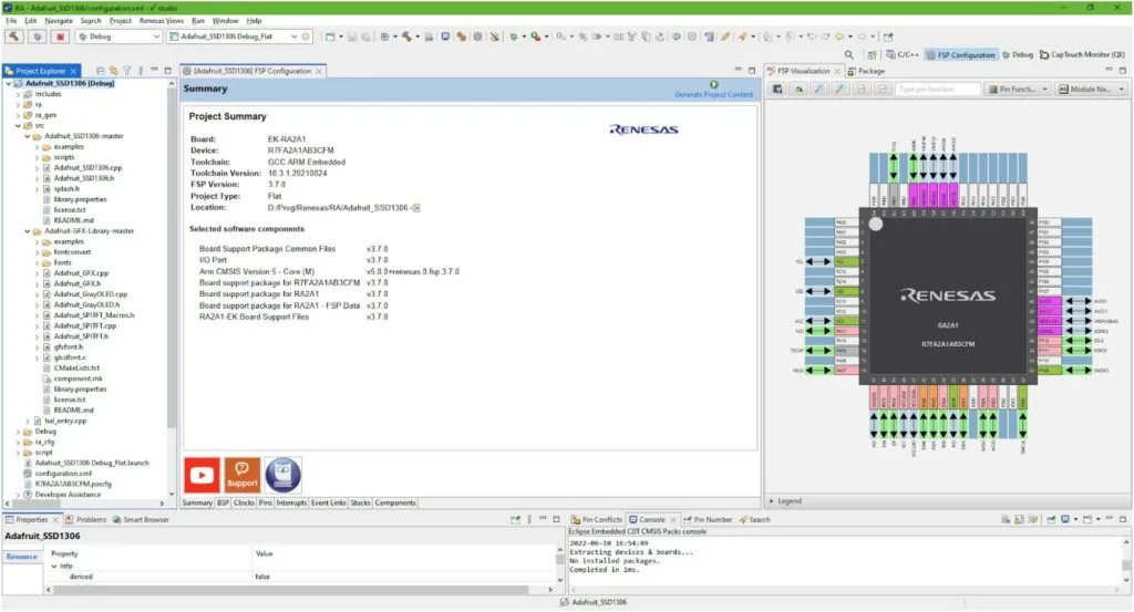
Let’s exclude the spare folders and files from build. We don’t need the “examples” and “scripts” folders in the “Adafruit_SSD1306-master” library and “examples” and “fontconvert” folders of the “Adafruit-GFX-library-master” library. To do this, right click on the previously named folders one by one, and select the “Property” line in the drop-down menu. In the opened window set the check “Exclude resource from build” (Figure 11).
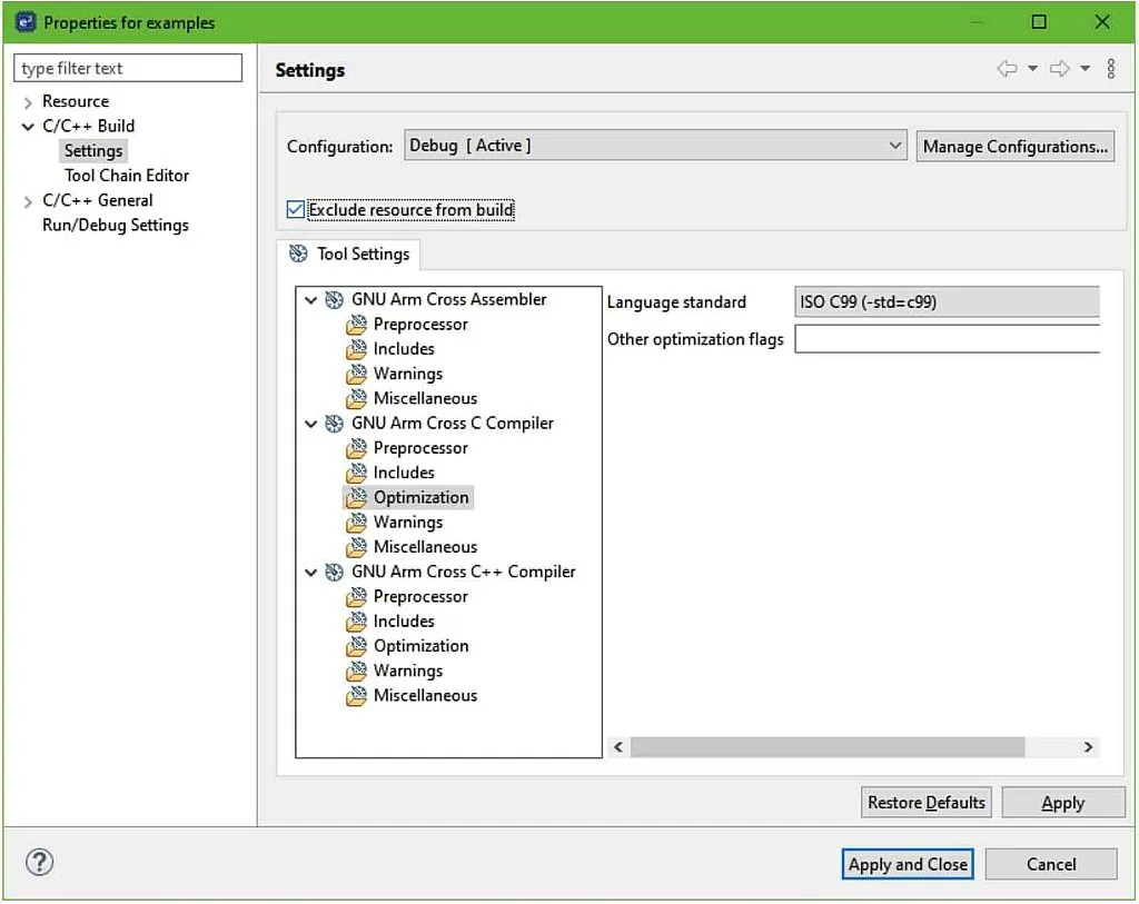
Also, in the same way, we need to exclude the files “Adafruit_GrayOLED.cpp”, “Adafruit_GrayOLED.h”, “Adafruit_SPITFT_Macros.h”, “Adafruit_SPITFT.cpp”, and “Adafruit_SPITFT.h”.
The next thing to do is to add the “Adafruit_SSD1306-master” and “Adafruit-GFX-library-master” directories to the include list. To do this, right click on the project name and select the “Properties”. In the drop-down list “C/C++ Build” select the line “Setting”. Then in the central part of the window in the “GNU Arm Cross C++ Compiler” select the line “Includes” (Figure 12).
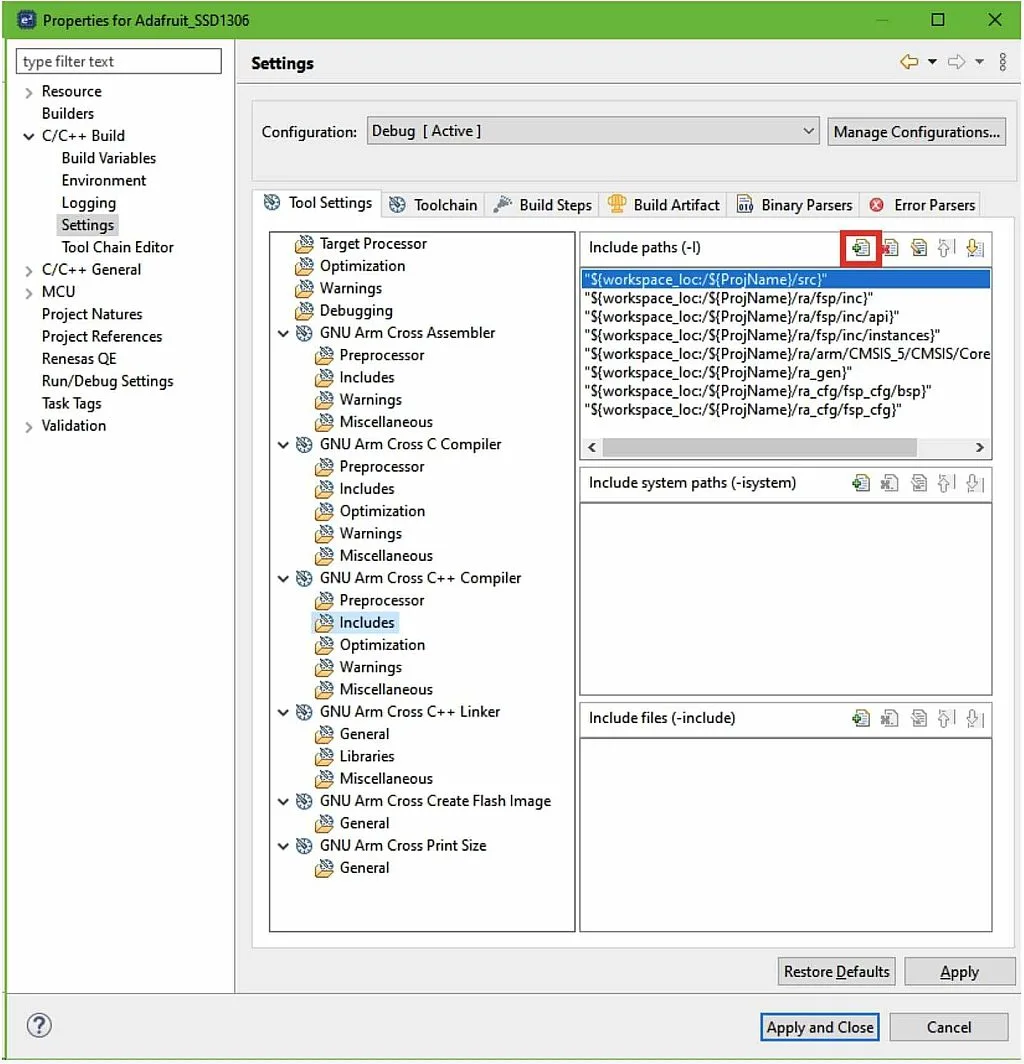
Click on the “Add…” button marked with the red frame in Figure 12. In the opened window click on the “Workspace…” button and select both “Adafruit_SSD1306-master” and “Adafruit-GFX-library-master” directories (Figure 13).
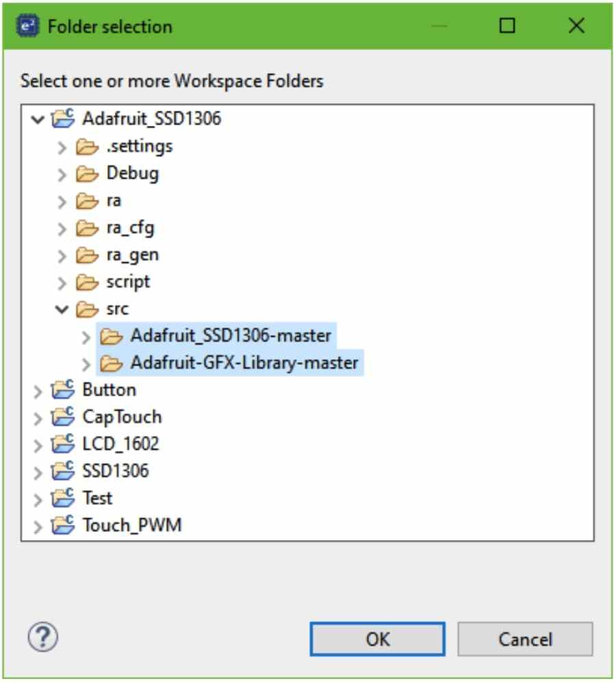
Then click on the “OK” button. Now you can see that your directories have been added to the include path, so you can click on the “Apply and Close” button.
You can try to build the project but, unsurprisingly, you’ll get several errors. Let’s get rid of them then. In this tutorial, I will not show the whole code of the Adafruit libraries as they are quite huge. I will just focus on the changes that we need to make. Let’s start with the Adafruit GFX library, as the SSD1306 library is based on it.
Here are the changes that need to be done in the “Adafruit_GFX.h” file.
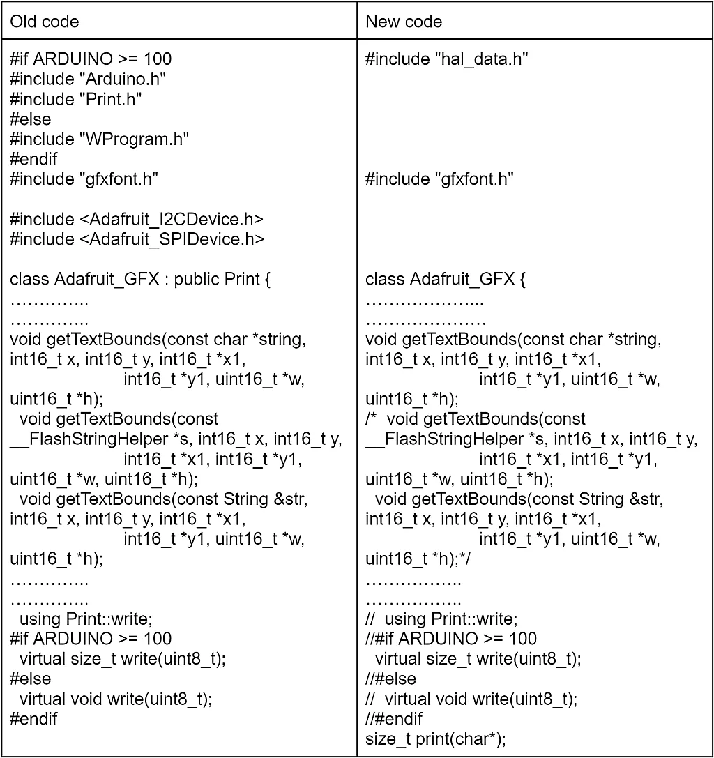
As you can see, there are only a few changes in it. First, we remove the Arduino-based header files and replace them with the “hal_data.h”. Also we remove the “Adafruit_I2CDevice.h” and “Adafruit_SPIDevice.h” headers not to dive deep into the Adafruit libraries. Anyway we will use the FSP-based I2C code in our program.
Initially the Adafruit_GFX class was based on the Print class but once again, I decided not to increase the levels of class inheritance, and made the Adafruit_GFX the basic class.
In the function “getTextBounds” we leave only the first declaration which has the first parameter “const char *string” because the RA compiler knows nothing about the __FlashStringHelper and String classes.
And finally, as we are not using the Print class, we can’t use its write method, so we need to comment out this line. Also, we need to leave the declaration of the method write with the size_t type, as in the “Adafruit_GFX.cpp” file it’s defined like this. Finally, we declare our own print method to print out the string of characters.
And so far there are all changes in this file. Let’s switch to the “Adafruit_GFX.cpp” file.
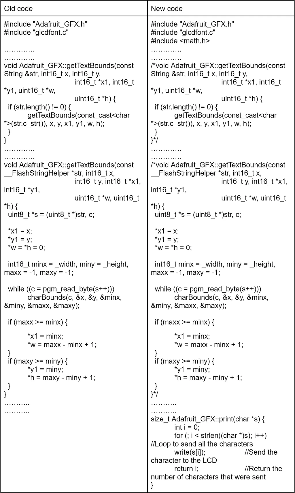
There are even fewer changes here. First, we need to include the “math.h” header file as it consists of some functions used in this file. Then we comment out the getTextBounds methods with the __FlashStringHelper and String types parameters.
And finally we create our own print method which accepts a single parameter s which represents the string to be written. It’s pretty simple. First we declare the i variable and assign its value as 0, this will be a counter of the characters. Then we make a for-type loop to write strlen(s) characters, where strlen() is the standard function which calculates the length of the string. We use the write method to write a single char s[i]. Finally, we return the i value which now represents the number of written characters.
Now, let’s switch to the “Adafruit_SSD1306.h” file.
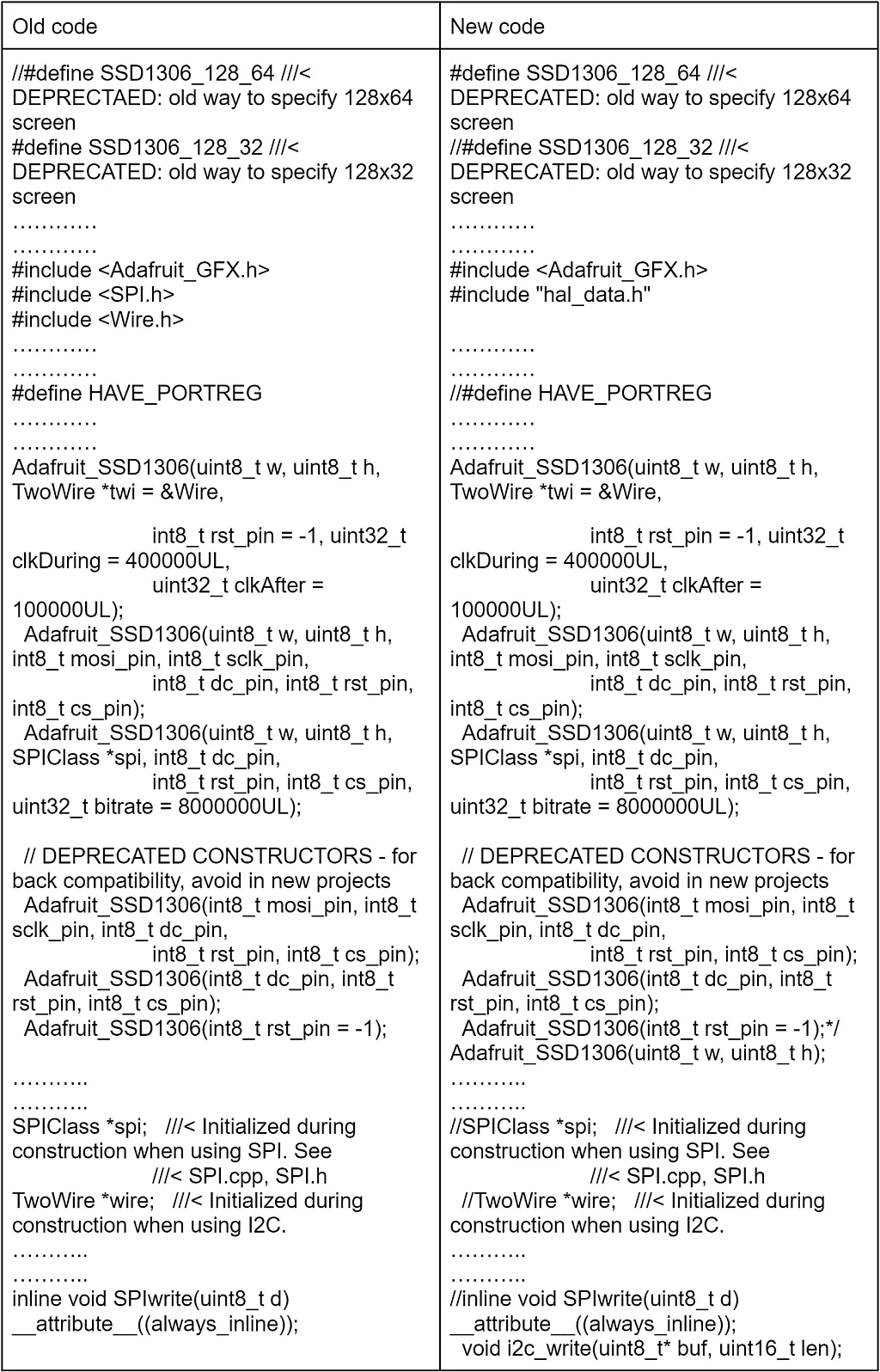
First, we comment out the definition SSD1306_128_32 and uncomment the definition SSD1306_128_64. This is actually not related to porting the library, it’s more about the display type we will use. As I have a 128x64 OLED, I use the SSD1306_128_64 macro. If you have another one, please select the corresponding macro definition.
Then we need to remove the “SPI.h” and “Wire.h” files including, because we will use our own I2C processing code. Also we will remove all the code related to the SPI because we’re not going to use the OLED with the SPI connection. Then we add the “hal_data.h” file as we do in all other files.
Also we comment out the definition of the HAVE_PORTREG macro. It seems to be used in SPI mode so we don’t need it.
Next, we comment out all the class constructors and create our own which will only define the width (w) and height (h) of the display in pixels.
Then we comment out the declaration of spi and wire objects of classes SPIClass and TwoWire, respectively.
Finally, we comment out the SPIwrite method and add the i2c_write method instead in which we will write the low level I2C communication routines.
The next file to change is “Adafruit_SSD1306.c”. And there will be a lot of changes because in this file the low-level communication between the MCU and display is implemented. As this file is really long (about 1200 lines) I think I will not show the old and new code like I did for other files, and will just describe what to change. Anyway, you can easily download the source project from this site and see the initial code.
#define I2C_TRANSACTION_BUSY_DELAY  	100


#include "Adafruit_SSD1306.h"
#include "splash.h"
#include <Adafruit_GFX.h>
#include <stdlib.h>
#include "hal_data.h"


// SOME DEFINES AND STATIC VARIABLES USED INTERNALLY -----------------------


#define ssd1306_swap(a, b)                                                 	\
(((a) ^= (b)), ((b) ^= (a)), ((a) ^= (b))) ///< No-temp-var swap operation


i2c_master_event_t g_i2c_callback_event;
void i2c_callback (i2c_master_callback_args_t * p_args)
{
    g_i2c_callback_event = p_args->event;
}


Adafruit_SSD1306::Adafruit_SSD1306(uint8_t w, uint8_t h)
        : Adafruit_GFX(w, h), buffer(NULL)
{
}
Adafruit_SSD1306::~Adafruit_SSD1306(void) {
    if (buffer) {
        free(buffer);
        buffer = NULL;
    }
}


// LOW-LEVEL UTILS ---------------------------------------------------------
void Adafruit_SSD1306::i2c_write(uint8_t* buf, uint16_t len)
{
    fsp_err_t err;
    uint32_t  timeout_ms = I2C_TRANSACTION_BUSY_DELAY;


    /* Send data to I2C slave */
    g_i2c_callback_event = I2C_MASTER_EVENT_ABORTED;


    err = R_IIC_MASTER_Write(&g_i2c_master0_ctrl, buf, len, false);
    if (err == FSP_SUCCESS)
    {
        /* Since there is nothing else to do, block until Callback triggers*/
        while ((I2C_MASTER_EVENT_TX_COMPLETE != g_i2c_callback_event) && timeout_ms)
        {
            R_BSP_SoftwareDelay(1U, BSP_DELAY_UNITS_MILLISECONDS);
            timeout_ms--;;
        }
        if (I2C_MASTER_EVENT_ABORTED == g_i2c_callback_event)
        {
            __BKPT(0);
        }
    }
}
void Adafruit_SSD1306::ssd1306_command1(uint8_t c) {
    uint8_t g_i2c_tx_buffer[2];
    g_i2c_tx_buffer[0] = 0x00;   // Co = 0, D/C = 0
    g_i2c_tx_buffer[1] = c;
    i2c_write(g_i2c_tx_buffer, 2);
}
void Adafruit_SSD1306::ssd1306_commandList(const uint8_t *c, uint8_t n) {
    uint8_t g_i2c_tx_buffer[n + 1];
    g_i2c_tx_buffer[0] = 0x00;
    for (uint8_t i = 0; i < n; i ++)
        g_i2c_tx_buffer[i + 1] = c[i];
    i2c_write(g_i2c_tx_buffer, n + 1);
}
bool Adafruit_SSD1306::begin(uint8_t vcs, uint8_t addr, bool reset,
                    bool periphBegin) {


    if ((!buffer) && !(buffer = (uint8_t *)malloc(WIDTH * ((HEIGHT + 7) / 8))))
        return false;


    clearDisplay();


#ifndef SSD1306_NO_SPLASH
    if (HEIGHT > 32) {
        drawBitmap((WIDTH - splash1_width) / 2, (HEIGHT - splash1_height) / 2,
                    splash1_data, splash1_width, splash1_height, 1);
    } else {
        drawBitmap((WIDTH - splash2_width) / 2, (HEIGHT - splash2_height) / 2,
                    splash2_data, splash2_width, splash2_height, 1);
    }
#endif


    vccstate = vcs;


    fsp_err_t err = FSP_SUCCESS;
    if (periphBegin)
        err = R_IIC_MASTER_Open(&g_i2c_master0_ctrl, &g_i2c_master0_cfg);
    if (err != FSP_SUCCESS)
        return false;
    // Init sequence
    static const uint8_t init1[] = {SSD1306_DISPLAYOFF,     	// 0xAE
                         SSD1306_SETDISPLAYCLOCKDIV, // 0xD5
                         0x80, // the suggested ratio 0x80
                         SSD1306_SETMULTIPLEX}; // 0xA8
    ssd1306_commandList(init1, sizeof(init1));
    ssd1306_command1(HEIGHT - 1);


    static const uint8_t init2[] = {SSD1306_SETDISPLAYOFFSET, // 0xD3
                         0x0,                  	// no offset
                         SSD1306_SETSTARTLINE | 0x0, // line #0
                         SSD1306_CHARGEPUMP};    	// 0x8D
    ssd1306_commandList(init2, sizeof(init2));


    ssd1306_command1((vccstate == SSD1306_EXTERNALVCC) ? 0x10 : 0x14);


    static const uint8_t init3[] = {SSD1306_MEMORYMODE, // 0x20
                         0x00, // 0x0 act like ks0108
                         SSD1306_SEGREMAP | 0x1,
                         SSD1306_COMSCANDEC};
    ssd1306_commandList(init3, sizeof(init3));


    uint8_t comPins = 0x02;
    contrast = 0x8F;


    if ((WIDTH == 128) && (HEIGHT == 32)) {
        comPins = 0x02;
        contrast = 0x8F;
    } else if ((WIDTH == 128) && (HEIGHT == 64)) {
        comPins = 0x12;
        contrast = (vccstate == SSD1306_EXTERNALVCC) ? 0x9F : 0xCF;
    } else if ((WIDTH == 96) && (HEIGHT == 16)) {
        comPins = 0x2; // ada x12
        contrast = (vccstate == SSD1306_EXTERNALVCC) ? 0x10 : 0xAF;
    } else {
        // Other screen varieties -- TBD
    }


    ssd1306_command1(SSD1306_SETCOMPINS);
    ssd1306_command1(comPins);
    ssd1306_command1(SSD1306_SETCONTRAST);
    ssd1306_command1(contrast);


    ssd1306_command1(SSD1306_SETPRECHARGE); // 0xd9
    ssd1306_command1((vccstate == SSD1306_EXTERNALVCC) ? 0x22 : 0xF1);
    static const uint8_t init5[] = {
        SSD1306_SETVCOMDETECT, // 0xDB
        0x40,
        SSD1306_DISPLAYALLON_RESUME, // 0xA4
        SSD1306_NORMALDISPLAY,   	// 0xA6
        SSD1306_DEACTIVATE_SCROLL,
        SSD1306_DISPLAYON}; // Main screen turn on
    ssd1306_commandList(init5, sizeof(init5));


    return true; // Success
}
void Adafruit_SSD1306::display(void) {
    static const uint8_t dlist1[] = {
        SSD1306_PAGEADDR,
        0,                  	// Page start address
        0xFF,               	// Page end (not really, but works here)
        SSD1306_COLUMNADDR, 0}; // Column start address
    uint8_t g_i2c_tx_buffer[17];


    ssd1306_commandList(dlist1, sizeof(dlist1));
    ssd1306_command1(WIDTH - 1); // Column end address
    uint16_t count = WIDTH * ((HEIGHT + 7) / 8);


    for (uint16_t i=0; i<count;)
    {
        // send a bunch of data in one xmission
        g_i2c_tx_buffer[0] = 0x40;
        for (uint8_t x=0; x<16; x++)
        {
            g_i2c_tx_buffer[x+1] = buffer[i];
            i++;
        }
        i2c_write(g_i2c_tx_buffer, 17);
    }
}
Here I wrote just the parts of the file in which I made the most changes. The added lines are, as usual, highlighted in green. As for the other minor changes, I’ll also mention them. The line numbers correspond to the updated file. The complete file along with the whole project can be found at the end of this tutorial in the archive “Tutorial 8.zip”.
In line 39 we define the I2C_TRANSACTION_BUSY_DELAY which is the max time that we wait for the I2C transaction to complete. Also in this part of the file we remove all the definitions except for the ssd1306_swap (lines 49-50). This macro swaps two variables a and b. The implementation of this operation is quite interesting (line 50) as it doesn’t require any temporary variable and uses just the XOR operations. Let’s consider in more detail how it works on the example of two values a = 0x15 (0b00010101) and b = 0x83 (0b10000011).
Operation | a | b |
Initial values | 0b00010101 | 0b10000011 |
a ^= b | 0b10010110 | 0b10000011 |
b ^= a | 0b10010110 | 0b00010101 |
a ^= b | 0b10000011 | 0b00010101 |
As you can see, this macro works well. In this library it is used to change the display orientation.
In line 44 we include the “stdlib.h” header file. It’s needed to use the memory allocation function malloc and free which we will consider later.
In line 45 we include the “hal_data.h” file to use the FSP generated definitions, macros and functions.
In line 52 we declare the variable g_i2c_callback_event of the type i2c_master_event. This variable consists of the event that has caused the IIC0 module interrupt.
In lines 53-56 there is the I2C callback function i2c_callback. If you remember we called it this when we configured the IIC0 module (Figure 8). The only thing we do in this function is save the event, which caused this interrupt, into the g_i2c_callback_event variable to process it later.
Next we delete all the class constructors and write our own (lines 58-61). As you can see, we transfer only two arguments in it which represent the width and the height of the OLED display in pixels. Inside this constructor we just call the constructor of the parent class Adafruit_GFX and pass the w and h parameters to it (line 59), and initialize the buffer pointer as NULL. This buffer is a very important thing. It is the array in which all the drawings occur like on a canvas. And then the content of this array is flushed to the display in the display method (lines 639-673).
In lines 66-71 there is the class destructor which we use as is. I just wrote it here to emphasize that we shouldn’t forget about it. Specifically, releasing memory when it’s not needed. The buffer variable is defined as just the pointer of the uint8_t* type. We declare it like this but not as a static array because we don’t initially know the OLED resolution, so the array size can be variable. In this case dynamic memory allocation is used, which we will consider quite soon. The memory is allocated from the heap region that’s why I told you to increase its size.
It's good manners to release the allocated memory when we no longer need it. So we do this by calling the free function (line 68) if the buffer was allocated (line 67). And then we assign the buffer pointer to NULL (line 69).
Next, we remove the method SPIwrite and replace it with the method i2c_write (lines 74-96). This method has two arguments: buf which is the array of the data to be sent to the I2C bus, and len which is the number of bytes to send.
In line 76 we declare the variable err of type fsp_err_t. It will consist of the result of the I2C transaction. In line 77 we declare the variable timeout_ms and assign the value I2C_TRANSATION_BUSY_DELAY to it. It will be used to count the milliseconds while the bus is busy.
In line 80 we assign the value I2C_MASTER_EVENT_ABORTED to the g_i2c_callback_event variable. Actually we could skip this line but it’s not a good thing to check the variable whose value was not assigned at all, and theoretically can be random when we enter this function.
In line 82 we invoke the R_IIC_MASTER_Write function, which implements sending the len number of bytes from the buffer buf to the I2C bus. The last parameter which is false now indicates whether we need to issue the restart event after the transaction is completed. The first parameter g_i2c_master0_ctrl is the IIC0 module control handle. Its first part of the name g_i2c_master0 is the one that we gave it during the configuration (Figure 8).
If the result of the operation is successful (line 83) we wait either while the g_i2c_callback_event becomes I2C_MASTER_EVENT_TX_COMPLETE (which means that the data has been sent successfully) or while timeout_ms becomes 0 (which means something went wrong and a timeout has occurred) (line 86). Inside this loop we perform the 1ms delay (line 88) and decrement the timeout_ms variable (line 89).
If, after the leaving the loop, the state of the g_i2c_callback_event is I2C_MASTER_EVENT_ABORTED (which means that the transaction was aborted for some reason), we call the function __BKPT(0); This function represents the software breakpoint, so if something goes wrong with the I2C communication, the program will be halted. Actually the main reason for this event is trying to use the I2C module prior to its opening by calling the R_IIC_MASTER_Open function.
This is everything about the i2c_write function. The next methods have the old name but their content has been replaced.
The ssd1306_command1 method (lines 110-115) sends a single command c to the display. All data sent to the display should be followed by the byte that indicates the type of data. If this byte is 0x00 then the sent byte(s) is(are) the command, and if it is 0x40, the following bytes are considered as the data to be displayed.
So in line 111 we declare the g_i2c_tx_buffer array of two uint8_t elements which is the array to be sent to the display via I2C bus. In line 112 we assign 0x00 to the first element of this array to indicate that we are going to send the command, and in line 113 we assign the command byte c to the second element of the array. Finally, in line 114 we send the two bytes via the I2C.
The next method ssd1306_commandList (lines 129-135) is very similar to the previous one. The difference is that we send not only one command but a series of commands in one transaction. This method has the following arguments: c is the pointer to the array of the commands to be sent, and n is the number of commands.
So in line 130 we declare the g_i2c_tx_buffer array which plays the same role as in the previous method but this time it has n+1 elements. In line 131 we assign 0x00 to the first element of this array to indicate that we are going to send the commands. Then we make the loop to copy all n values from the c parameter to the g_i2c_tx_buffer (lines 132-133). Finally, in line 134 we send the buffer via the I2C bus.
The next method in which we need to make changes is begin (lines 188-268). In line 191 we allocate the required amount of memory for the buffer array. If you read the data sheet of the SSD1306 you can see there that the display memory is organized in the way that each column is grouped by bytes. So for instance if the display height is 64 pixels, there are 8 bytes for each column (8 bytes x 8 pixels = 64 pixels). That’s what we divide the HEIGHT by 8. Adding 7 to the HEIGHT is excessive but it allows us to make sure that we cover the whole area of the display even if its height is not easily divisible by 8.
If for some reason the memory was not allocated or the buffer is NULL we return false to indicate that something went wrong (line 192).
In line 194 we clear the display buffer. Again, even though we call the function as clearDisplay, in fact we clear just the buffer array but not the display itself.
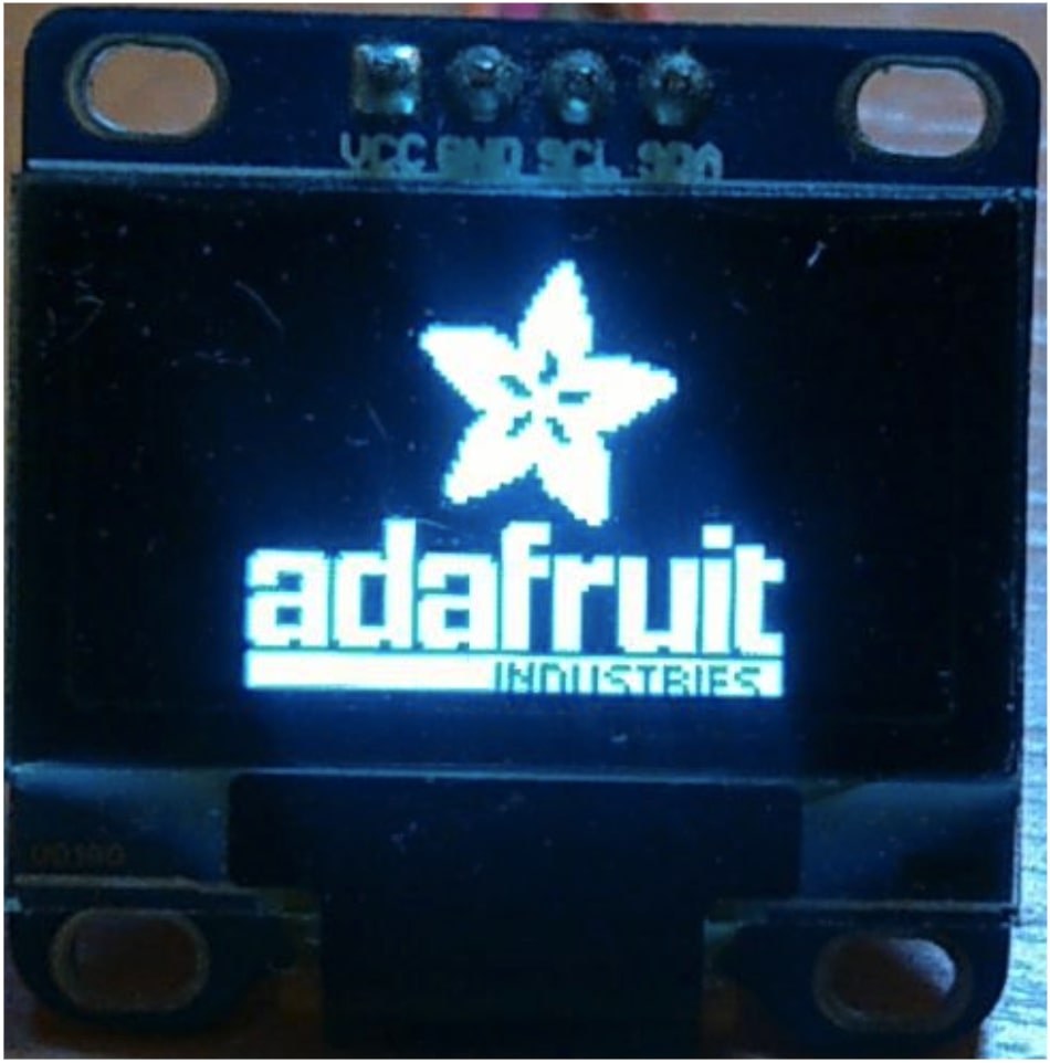
Lines 196-204 are optional. They allow you to preload the display buffer with the Adafruit logo advertisement which is located in the “splash.h” file. There are two variants of this logo: for 128x64 display (lines 197-199) or for 128x32 display (lines 200-203). If you don’t need this, you can define the macro SSD1306_NO_SPLASH somewhere upper in this file.
In line 206 we assign the vccstate variable with the vcs value which we pass to this function as a parameter. This variable can have two values: SSD1306_SWITCHCAPVCC if we want to use the internal boost converter to generate the panel driving voltage (7-15 V), or SSD1306_EXTERNALVCC if we will apply this voltage externally. In our case we will use the first option.
In line 208 we declare the variable err of type fsp_err_t and assign it with the value FSP_SUCCESS.
In line 209 we check the parameter periphBegin. If it is true then we need to initialize the IIC0 module, otherwise it has already been initialized and we don’t need to do it twice.
In line 210 we invoke the function R_IIC_MASTER_Open which assigns the required parameters which we set in the FSP configurator to the IIC0 module.
If the result of this function is not FSP_SUCCESS (line 211) we return false.
Otherwise we perform the display initialization sequence. I will not consider it here in detail, for more information please refer to the SSD1306 data sheet.
Please note that we need to remove the PROGMEM everywhere in the text, not only in this file but also in the “splash.h”. This modifier is used in the Arduino platform to indicate that this array is stored in the program memory. But actually if we define the const, it’s stored in the program memory automatically.
Also, we need to remove the macros TRANSACTION_START and TRANSACTION_END as they are not used anymore.
The last method in which we need to make significant changes is print (lines 639 - 673).
In line 640 we declare the array dlist1 to send the command to the OLED to prepare it for the image data reception. I actually didn’t dive deeply into it, and accepted it for granted.
In line 645 we again declare the g_i2c_tx_buffer array but this time it has 17 elements.
In lines 647 and 648 we send the required commands before the data transmission.
In line 659 we declare the count variable which represents the number of bytes to be sent to the display. As you can see, this number corresponds to the buffer size.
In lines 661-671 there is the loop to send the whole buffer to the display. Please pay attention that even though we use the for loop, we don’t increment the loop variable in line 661, as we will do this later, in line 668. In line 664 we assign the value 0x40 as the first element of the g_i2c_tx_buffer array. As I mentioned before, if the first byte is 0x40, the following data is considered by the display as image data. In line 665 we make another for loop to fill the g_i2c_tx_buffer with the 16 bytes (lines 667). Also we increment the i value here to fill the g_i2c_tx_buffer array with the next data in the next iteration of the upper loop. In line 670 we send 17 bytes to the display. And that’s all we need to do in this function.
At this point we will stop considering the Adafruit SSD1306 library because all important things have been already explained. As I mentioned before, you can see the whole project at the end of the tutorial.
Writing the Test Code and Testing
Now we need to write some code in the “hal_entry.cpp” file. If you are attentive enough you may notice that as we use the C++ language in this project, the extension of the “hal_entry” file is “cpp” instead of just “c”. This doesn’t affect anything for us though.
#include "hal_data.h"
#include "Adafruit_SSD1306.h"


FSP_CPP_HEADER
void R_BSP_WarmStart(bsp_warm_start_event_t event);
FSP_CPP_FOOTER


Adafruit_SSD1306 display(128, 64);


/*******************************************************************************************************************//**
* main() is generated by the RA Configuration editor and is used to generate threads if an RTOS is used. This function
* is called by main() when no RTOS is used.
*********************************************************************************************************************/
void hal_entry(void)
{
    /* TODO: add your own code here */
    R_BSP_SoftwareDelay(1000, BSP_DELAY_UNITS_MILLISECONDS);
    display.begin(SSD1306_SWITCHCAPVCC, 0x3C, false, true); //Initialize OLED display with the I2C addr 0x3C (for the 128x64)
    display.display();


    while (1);
#if BSP_TZ_SECURE_BUILD
    /* Enter non-secure code */
    R_BSP_NonSecureEnter();
#endif
}
As you see, the code is very short, we add just 6 lines. I made it this way intentionally because the tutorial already is quite long and meaty. We will use this display at least twice in the next tutorials so we will consider operation with this library in more detail later.
So, in line 2 we include the “Adafruit_SSD1306.h” file to use the ported Adafruit SSD1306 library. In line 8 we create the object of the class Adaftuit_SSD1306 called display. In the constructor we set the display resolution 128x64 pixels.
Then in the main function of the program we first implement a 1000ms delay (line 17) to wait while the internal voltage generator of the display stabilizes, then call the begin method (line 18). This method must be called prior to all operations with the display. The first parameter of this function sets the panel voltage source. As I mentioned before, it should be SSD1306_SWITCHCAPVCC. The second parameter is the address of the display. I also already mentioned that it should be 0x3C. The third parameter regards using the reset pin of the display. Actually it is a very useful pin when the display hangs but for some reason this pin is not connected to the output header. So as we don’t have this pin we set this parameter as false. The last parameter is periphBegin which I considered earlier. We set it as true to configure the IIC0 module in this function. Also, as we didn’t define the SSD1306_NO_SPLASH macro after implementation of this function the display buffer will be filled with the Adafruit logo. Let’s not do anything else and send this logo to the display by calling the display method (line 19).
As we don’t do anything else in this program, we leave the main loop of the program blank (line 21).
Now we’re ready for the practical work. Let’s connect the display to the board according to Figure 2. Then connect the board to the PC, make and debug the project. If you did everything correctly you should see the following image (Figure 14).
If you see nothing, check the module connection to the board. Also examine the display itself and the flat cable between the display and the board if they are not broken. Then check the jumper at the back side of the module, it should be in position 0x78. Finally, if you have a logic analyzer, check the signals on the SCL and SDA lines.
As I said before, we will consider operation with this library in more detail in the following tutorials but if you don’t have any patience, you can read the GFX and SSD1306 libraries documentation here http://adafruit.github.io/Adafruit-GFX-Library/html/class_adafruit___g_f_x.html and here https://adafruit.github.io/Adafruit_SSD1306/html/class_adafruit___s_s_d1306.html, respectively.
As homework, try to do some experiments with the Adafruit libraries and draw some primitives like line, square, circle, triangle etc.
Project Files

Get the latest tools and tutorials, fresh from the toaster.


