Dot Matrix LED Display Digital Clock - Part 3
Published
We’ve already discussed the hardware and software of the dot matrix LED display digital clock. Finally, we’re in the last part and this time we are going to check the PCBs, the assembled digital clock, and discuss how to set the digital clock using the tactile switches. But before that, if you still don’t know how to burn the bootloader of the Arduino Uno to the ATmega328P-PU MCU and program it, you can check part 4 of the non-contact forehead infrared thermometer tutorial here: Non-contact Forehead Infrared Thermometer - Part 4
PCB Design


Project Files
Actual PCB Images
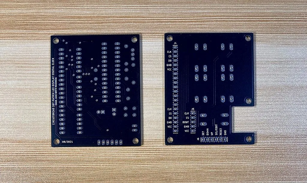
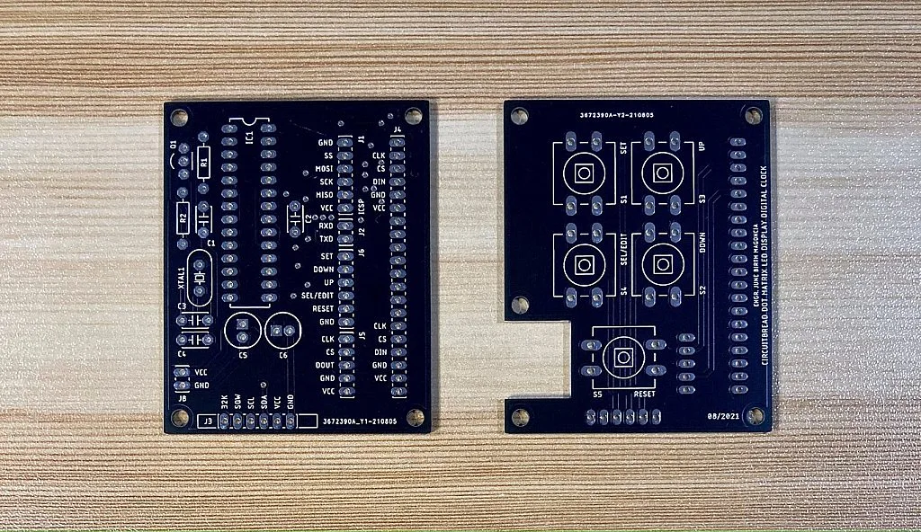
So there are two PCBs here. The first one is where we mount the MCU and other components of the digital clock except for the tactile switches which are mounted on the second PCB. As you can see, both PCBs have this 20-pin header (J4). That is where we will solder a 20-pin female header and we are going to attach the two PCBs to the two 4-in-1 MAX7219 dot matrix LED display modules through the 20-pin female header of the PCBs and the 5-pin right angled male header pin of the display modules. Usually, there’s only one 5-pin right angle male header soldered on the right side of the 4-in-1 MAX7219 dot matrix LED display module. So you still need to solder another 5-pin right angle male header on the left side of the 4-in-1 MAX7219 dot matrix LED display module.
Assembling Dot Matrix LED Display Digital Clock


 attached to the Digital Clock MCU PCB")

")
")
Programming the ATmega328-PU
")
If you already know how to burn the Arduino Uno bootloader to the ATmega328P-PU MCU and upload the code using a programmer, after assembling the digital clock, you can connect your programmer to the ICSP header (J1) of the digital clock MCU PCB.
")
After burning the bootloader and uploading the code, the digital clock can now operate in standalone mode by connecting a 5V/1A power supply to the header J8 of the MCU PCB.
Setting the Digital Clock
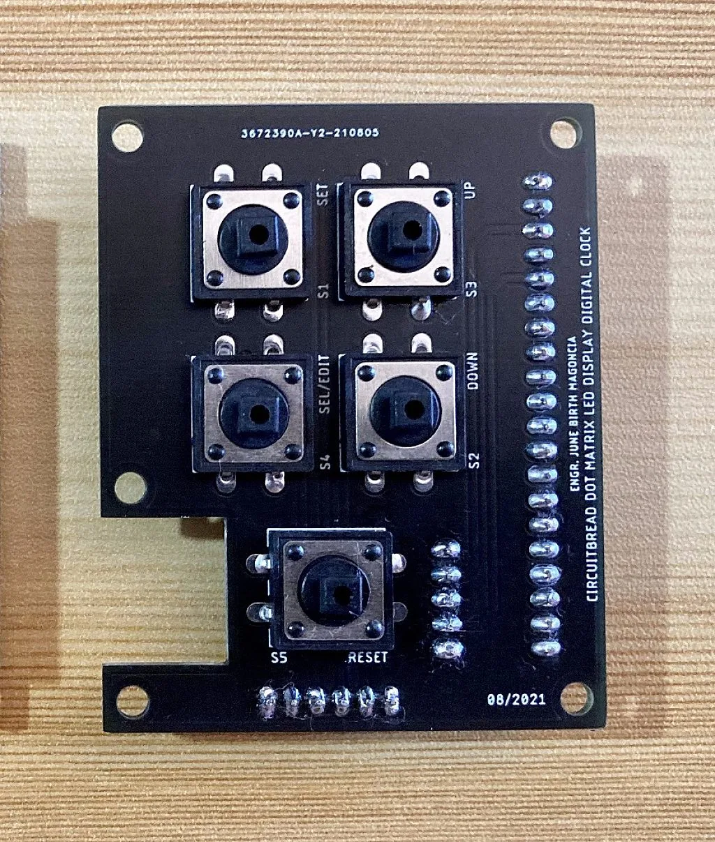
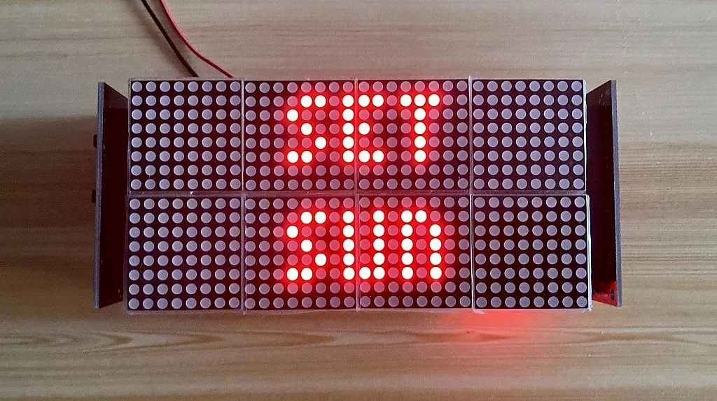
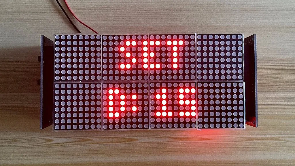
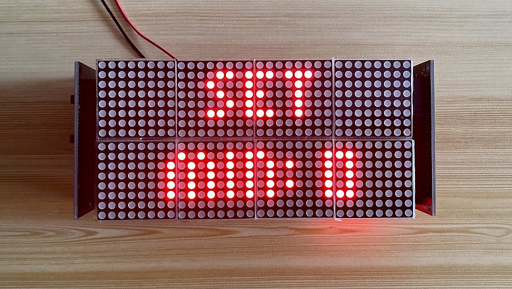
So the image above shows the second PCB of the digital clock where the tactile switches that set the digital clock are mounted. There are 5 tactile switches but the 5th switch is for resetting the MCU manually. Only switch 1 to 4 are used to set the digital clock. So for example, let’s say we want to set the time and date to Friday - October 15, 2021 10:20:30 AM, the first thing that we should do is press the SET button.
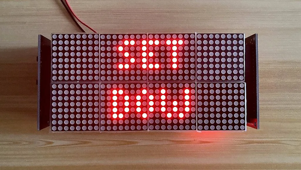
After pressing the SET button, the word SET will be displayed on Zone 0 and in Zone 1, the first setting that will appear is DOW. However, you can select DATE or TIME using the DOWN or UP button, but let’s set the DOW first by pressing the SEL/EDIT button.
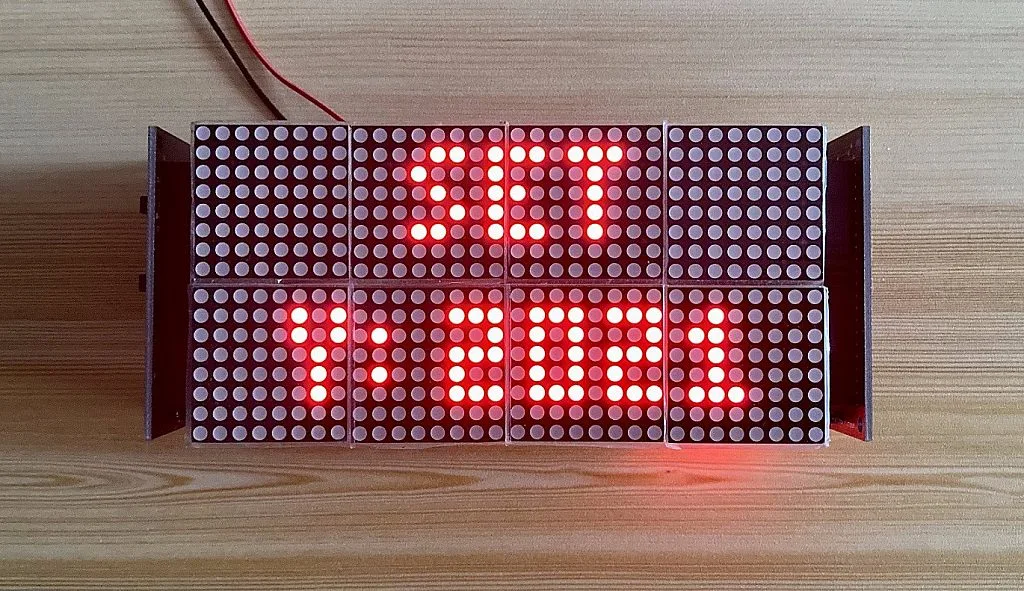
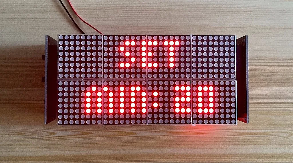
After pressing the SEL/EDIT button, Sunday (SUN) will be displayed on Zone 1. To change it to Friday (FRI), use the UP or DOWN button.
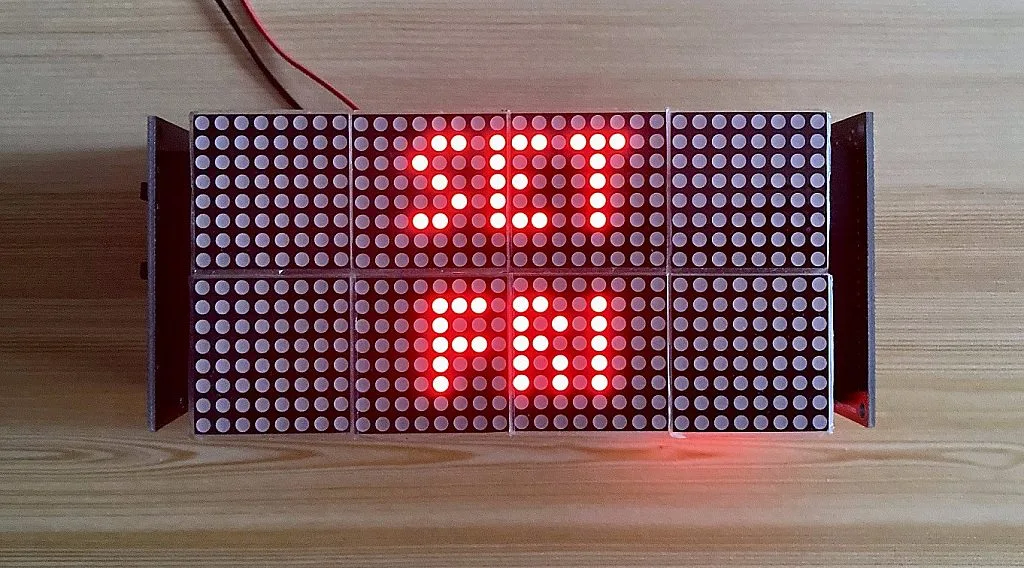
Then press the SEL/EDIT button again to set the DOW. Zone 1 will display DOW again after setting the DOW.
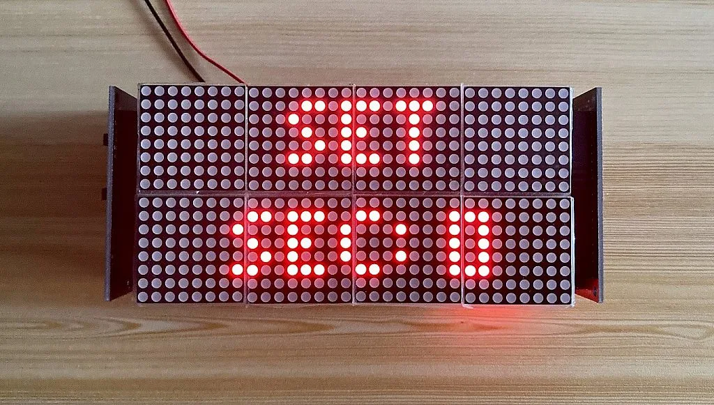
Press the UP button to move to DATE.
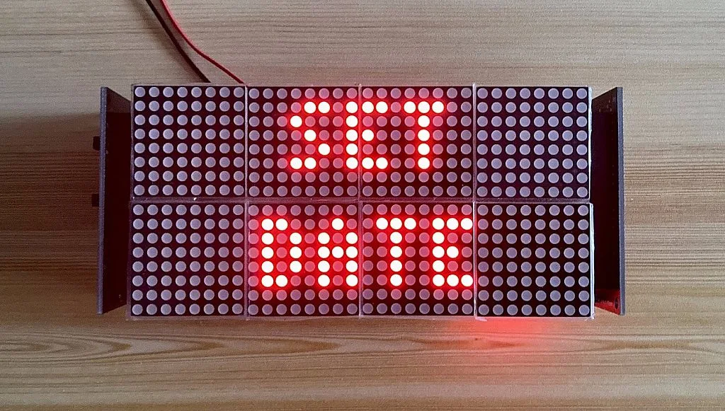
Then press the SEL/EDIT button to edit the day, month, and year.
The first date that will appear is 1. To change this to 15, use the UP or DOWN button.
Then press the SEL/EDIT button to move to month.

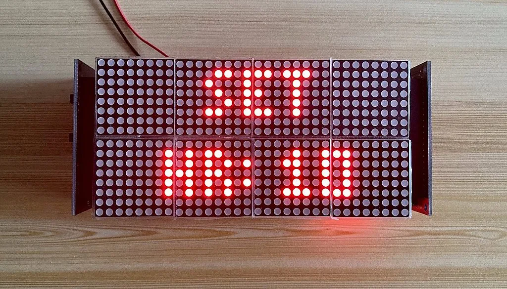
The first month that will appear is 1 (January). To select 10 (October), use the UP or DOWN button again.

Then press the SEL/EDIT button again to select the month and move to the year.
Since the first year that will appear here is 2021, there’s no need to edit it at the time of writing this. We will just press the SEL/EDIT button to finally set the DATE of the digital clock. After pressing the SEL/EDIT button, Zone 1 will display DATE again.
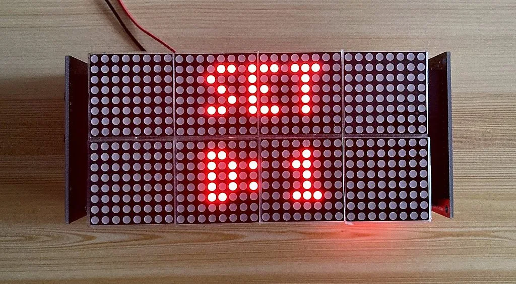
To move to TIME, press the UP button.

Then press the SEL/EDIT button to edit the hour, minute, and second.
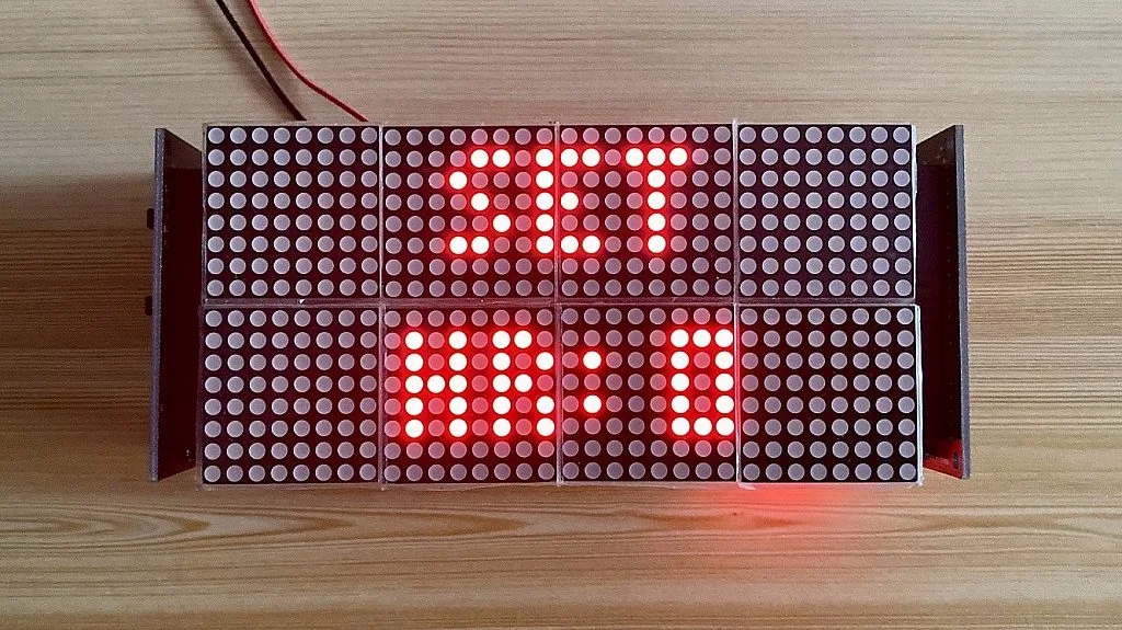
So initially, the hour is 0 (12AM). Use the UP or DOWN button again to change this to 10 (10AM).
Then press the SEL/EDIT button to move to minute.
So again, initially the minute is 0. Use the UP or DOWN button again to set it to 20.
Press the SEL/EDIT button again to move to second.
Use the UP or DOWN button to set it to 30.
And press the SEL/EDIT button to finally set the TIME of the digital clock.
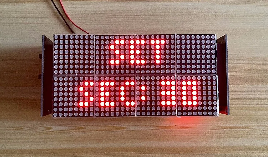
Zone 1 will display TIME again after pressing the SEL/EDIT button. So now, we have set the DOW, DATE, and TIME. To display the time on Zone 0 and date on Zone 1, press the SET button.
Conclusion
So that’s all! I hope you enjoyed reading this project/tutorial and I hope this will help you if you plan to make a digital clock using an Arduino Uno (or a minimal Arduino Uno), an RTC module, and a dot matrix LED display. If you have any questions, feel free to leave a comment below or contact us.
Bill of Materials
| Part | Estimated Cost |
| 1. ATmega328P-PU | ~$2.25 |
| 2. 28-pin IC Socket | ~$0.13 |
| 3. 2pcs. 0.1uF Ceramic Capacitors | ~$0.04 |
| 4. 16MHz Crystal | ~$0.24 |
| 5. 2pcs. 22pF Ceramic Capacitors | ~$0.04 |
| 6. 10kΩ Resistor | ~$0.01 |
| 7. DS3231 Precision Real-Time Clock (RTC) Module | ~$1.32 |
| 8. 2pcs. 4-in-1 MAX7219 Dot Matrix LED Display Modules | ~$9.24 |
| 9. 5pcs. 12mm Tactile Switches | ~$0.26 |
| 10. 2N3904 BJT | ~$0.014 |
| 11. 1kΩ Resistor | ~$0.01 |
| 12. 2pcs. 470uF Electrolytic Capacitors | ~$0.056 |
| 13. Male and Female Headers | ~$0.52 |
| 14. microUSB Breakout Board | ~$0.12 |
| 15. PCBs | $6.50 (Shipping fee not included. 5pcs 2 PCB designs. Ordered from Elecrow.) |
| Estimated Total Cost | ~$20.75 |
Libraries
- Rinky-Dink Electronics DS3231 Library (Download the DS3231 zip file, unzip it, and put it on the Arduino Libraries folder or you can directly add the DS3231.zip library using Arduino IDE under Sketch Menu > Include Library > Add .ZIP library)
- MajicDesigns MAX72xx LED Matrix Display Library v3.3.0 (Installed using Arduino IDE Library Manager)
- MajicDesigns MD_Parola Library v3.5.6 (Installed using Arduino IDE Library Manager)
- For the Font_Data header, put it inside the src folder of the MD_MAX72XX library. (Arduino\libraries\MD_MAX72XX\src)

Authored By
JB Magoncia
JB is an Electronics Engineer who is interested in audio, embedded systems, and PCB design. He is one of CircuitBread Engineers. JB is also a musician who mainly plays piano/keyboard but can also play bass, guitar, and drums. He currently lives in Cagayan de Oro, Philippines.

Related Tutorials


Related EE FAQs
 work?")
How do Analog to Digital Converters (ADCs) work?

Answered by Uma Bharathi D

What's the difference between a regular relay and a power relay?

Answered by Jayesh Upadhyay

What is a PWM signal?
Answered by Jayesh Upadhyay

Why is RAM faster than other memories?
Answered by Jayesh Upadhyay

Where can I receive design help for my projects?

Answered by Josh Bishop
Explore CircuitBread
- 244 Tutorials
- 9 Textbooks
- 12 Study Guides
- 31 Tools
- 104 EE FAQs
- 295 Equations Library
- 213 Reference Materials
- 97 Glossary of Terms
Friends of CircuitBread
-

Free Industry Lead Time Monitor
-

Request A Product Sample
-

Power Supply Related Technical Resources + 1 Perk


Get the latest tools and tutorials, fresh from the toaster.


