How to Interface 16x2 Character Liquid Crystal Display (1602 LCD) | Renesas RL78 - 8
Published
Hi! Welcome back again to CircuitBread. In our previous tutorial, we discussed the RL78 timer array unit (TAU), created a microsecond delay function delay_us(), and created a delay library by combining the millisecond delay function delay_ms() and the microsecond delay function delay_us(). As promised, in this tutorial we will interface a device widely used by hobbyists with the RL78/G14 MCU.
Based on the tutorial’s title, it’s already obvious that we’re going to use the 1602 LCD. The first reason I chose this device is that this device is cheap and you can easily purchase it nowadays. But, I can’t find a tutorial with proper instructions on how to program and interface with it using the RL78 MCU. The second reason is that CircuitBread has a tutorial of this device interfaced with a PIC MCU written by Sergey: Embedded C Programming with the PIC18F14K50 - 18. Using 1602 Character LCD with the HD44780 Driver. We can just refer to Sergey’s tutorial to know how the LCD and the functions that drive the LCD operate.
The third reason I chose this device is that when I checked the functions, it looks like we can port them to work with the RL78 MCU as long as we know how to set the RL78 GPIOs and have delay functions which we have already discussed in the previous tutorials. I just want to tell you in advance that this tutorial is actually more about porting the functions that Sergey created for the PIC MCUs to the RL78 MCUs. I will not explain the LCD and the functions operation anymore as it will just make the tutorial longer. If you want to know about the operation of the LCD and the functions, again, please refer to Sergey’s tutorial, Embedded C Programming with the PIC18F14K50 - 18. Using 1602 Character LCD with the HD44780 Driver.
Schematic Diagram
Before we start porting the functions, let’s check the hardware connection of the 1602 LCD and the RL78/G14 FPB first. Please see the schematic diagram below.
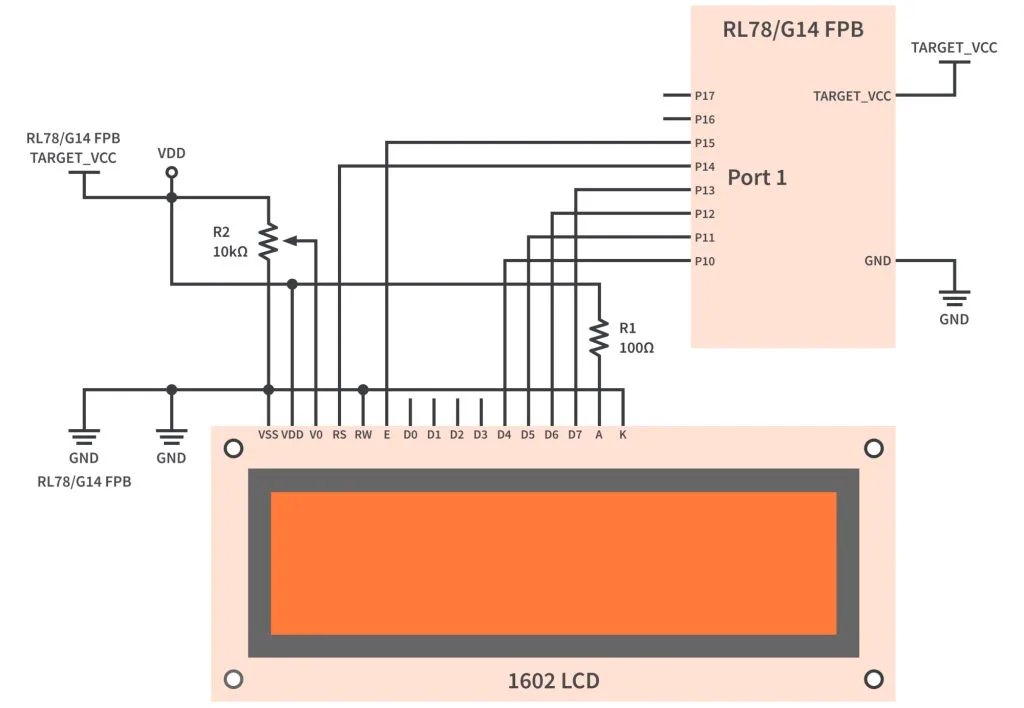
As you can see in figure 1, the first (VSS) and second (VDD) pins of the LCD are for the power supply. Normally, the operating voltage of the LCD is 5V. However, there are also LCDs that operate at 3.3V. So make sure that you have the 5V version then connect the VSS pin and the VDD pin of the LCD to the GND pin and the TARGET_VCC pin of the RL78/G14 FPB, respectively. Figure 2 shows what headers TARGET_VCC, GND, and Port 1 pins are connected to.

The V0 pin is used to set the contrast of the LCD. As shown in figure 1, you can connect it to the wiper terminal of a 10kΩ potentiometer or a trimmer so you can easily adjust the contrast of the LCD.
The RS pin which is the data/command input is connected to pin P14 of the RL78/G14 MCU while the RW pin for read/write input is just connected to the GND as the data only goes from the MCU to the LCD. The E pin of the LCD which is the clock input is connected to pin P15 of the RL78/G14 MCU.
We will only use 4-bits of the 8-bit parallel interface of the LCD. So only D4-D7 pins will be used and connected to P10-P13 pins of the RL78/G14 MCU.
The A and K pins are for the LCD backlight power supply. Connect the A pin and the K pin to the TARGET_VCC pin and GND pin of the RL78/G14 FPB, respectively. Don’t forget to add a series resistor (22-47Ω would be ideal but I used a 100Ω resistor) as shown in the schematic diagram.
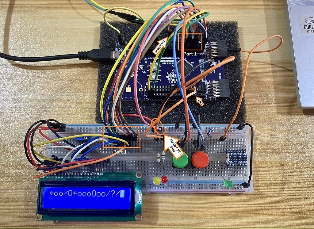
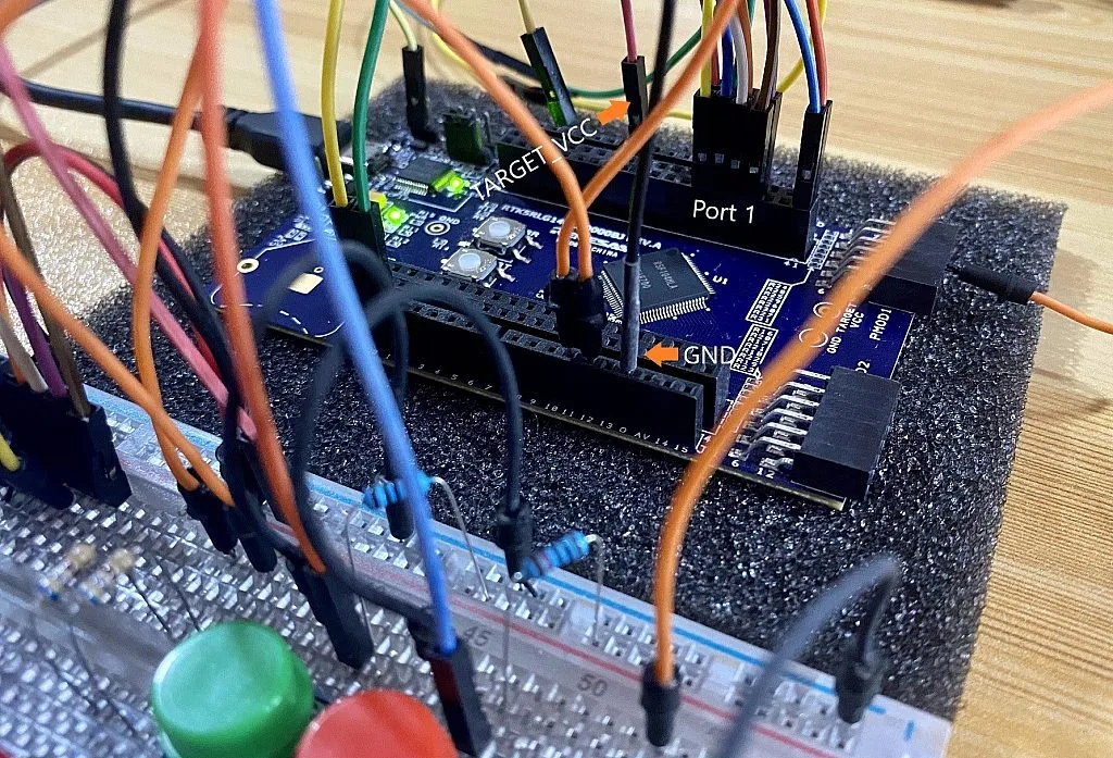
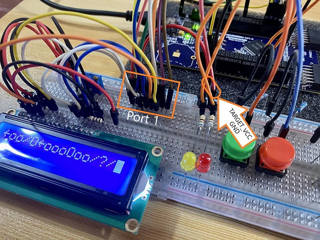
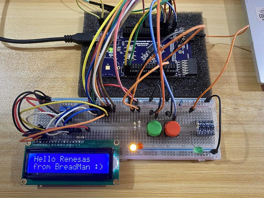
Figure 3 shows the connection of the RL78/G14 FPB and the 1602 LCD in reality. Just please ignore the other components (LEDs and switches) in the pictures. They’re just there so I can easily use them if ever I want to test something. So that’s all for the hardware, let’s proceed to the functions.
Porting the LCD Functions
Below is the list of functions that you can find in Sergey’s tutorial. Actually, there are just seven functions in the Embedded C Programming with the PIC18F14K50 - 18. Using 1602 Character LCD with the HD44780 Driver tutorial. However, I added the lcd_clear() function so we can use it later to easily clear the display in our sample code.
void lcd_init(uint8_t cursor, uint8_t blink);          	//  Initialize the LCD
void lcd_command(uint8_t command);                     	//  Send the command to the LCD
void lcd_send(uint8_t value, uint8_t rs);  	        	//  Send any data to the LCD
void lcd_write(char *s);                   	        	//  Write the string at the LCD
void lcd_data(uint8_t data);               	        	//  Send the character to the LCD
void lcd_set_cursor(uint8_t x, uint8_t y);             	//  Set cursor at the specified position
void lcd_create_char(uint8_t addr, uint8_t *data);     	//  Create a custom character
void lcd_clear(void);	                                //	Clear the screen
We will start with the lcd_init() function as it’s the first function that will be called to initialize the LCD. Here’s the function’s definition in Sergey’s tutorial:
void lcd_init(uint8_t cursor, uint8_t blink)    //    Initialize LCD
{
    lcd_command(0x30);    //    Try to use 8-bit interface
    __delay_us(4200);     //    Delay for command implementation
    lcd_command(0x30);    //    Try 8-bit interface one more time
    lcd_command(0x28);    //    Set 4-bit interface, two lines
    lcd_command(0x08);    //    Turn off the display
    lcd_command(0x01);    //    Clear the display and reset the address to 0
    __delay_us(4200);     //    Delay for command implementation
    lcd_command(0x06);    //    Cursor move direction from left to right
    lcd_command(0x0C | (cursor << 1) | blink);    //    Turn on display, set the cursor and blinking parameters
}
There are two functions used inside the lcd_init() function, lcd_command() and __delay_us() functions. The lcd_command() function is one of the LCD functions so we’ll just leave it like that. But we’re going to replace the __delay_us() function with the microsecond delay function that we created in the previous tutorial. We’ll change line 4 and line 9 so our new lcd_init() function definition for the RL78 MCU is:
void lcd_init(uint8_t cursor, uint8_t blink)    //    Initialize LCD
{
    lcd_command(0x30);      //    Try to use 8-bit interface
    delay_us(4200);         //    Delay for command implementation
    lcd_command(0x30);      //    Try 8-bit interface one more time
    lcd_command(0x28);      //    Set 4-bit interface, two lines
    lcd_command(0x08);      //    Turn off the display
    lcd_command(0x01);      //    Clear the display and reset the address to 0
    delay_us(4200);         //    Delay for command implementation
    lcd_command(0x06);      //    Cursor move direction from left to right
    lcd_command(0x0C | (cursor << 1) | blink);    //    Turn on display, set the cursor and blinking parameters
}
Now, let’s proceed to the lcd_command() function. As you can see below, inside the body of the lcd_command() function, we only have a line that calls the lcd_send() function. The lcd_send() function is also one of the LCD functions. So we don’t need to change anything for the lcd_command() function. Let’s proceed to the lcd_send() function.
void lcd_command(uint8_t command)    //    Send command to LCD
{
    lcd_send(command, 0);    //    Issue lcd_send function with RS = 0
}
If you’re familiar with the PIC MCUs, you’ll notice that the lcd_send() function below uses PORTC of the PIC18F14K50 MCU. Pins RC0-RC3 for the data pins D4-D7, RC4 for the RS pin, and RC5 for the E pin. In the schematic diagram shown in figure 1, we used Port 1 of the RL78/G14 MCU. We connected the LCD data pins D4-D7 to pins P10-P13 of the RL78/G14 MCU, the RS pin to pin P14, and E pin to pin P15. So let’s change the code lines below based on these connections.
void lcd_send(uint8_t value, uint8_t rs)    //    Send any data to LCD
{
    LATCbits.LC4 = rs;  	       //    Set RS pin (data/command)
    LATCbits.LC5 = 1;   	       //    Set E pin high to start the pulse
    LATC &= 0xF0;                  //    Clear the lower nibble of the LATC (set RC0-RC4 low)
    LATC|=(value & 0xF0) >> 4;     //    Send the upper nibble of the "value" to LCD
    __delay_us(1);      	       //    Delay needed by the driver
    LATCbits.LC5 = 0;   	       //    Set E pin low to finish the pulse
    __delay_us(1);      	       //    Delay needed by the driver
    LATCbits.LC5 = 1;   	       //    Set E pin high to start the pulse
    LATC &= 0xF0;                  //    Clear the lower nibble of the LATC (set RC0-RC4 low)
    LATC |= value & 0x0F;          //    Send the lower nibble of the "value" to LCD
    __delay_us(1);                 //    Delay needed by the driver
    LATCbits.LC5 = 0;              //    Set E pin low to finish the pulse
    __delay_us(40);                //    Delay more than 37 us to implement the command
}
- In line 3, we’ll change
LATCbits.LC4toP1_bit.no4. - In lines 4, 8, 10, and 14, we’ll change
LATCbits.LC5toP1_bit.no5. - In lines 5, 6, 11, and 12, we’ll change
LATCtoP1. - In lines 7, 9, and 13, we’ll change
__delay_us(1)todelay_1us(). You can also usedelay_us(1). - In line 15, we’ll change
__delay_us(40)todelay_us(40).
So here’s the new function definition of the lcd_send() function for the RL78 MCU:
void lcd_send(uint8_t value, uint8_t rs)	//	Send any data to LCD
{
	P1_bit.no4 = rs;			//	Set Port RS pin (data/command). P14 assigned to LCD RS pin.
	P1_bit.no5 = 1;   			//	Set E pin high to start the pulse. P15 assigned to LCD E pin.
	P1 &= 0xF0;					//	Clear the lower nibble of P1 (set P10-P13 low)
	P1 |= (value & 0xF0) >> 4;	//	Send the upper nibble of the "value" to LCD
	delay_1us();      			//	Delay needed by the driver
	P1_bit.no5 = 0;   			//	Set E pin low to finish the pulse
	delay_1us();      			//	Delay needed by the driver
	P1_bit.no5 = 1;   			//	Set E pin high to start the pulse
	P1 &= 0xF0;  				//	Clear the lower nibble of P1 (set P10-P13 low)
	P1 |= value & 0x0F;			//	Send the lower nibble of the "value" to LCD
	delay_1us();				//	Delay needed by the driver
	P1_bit.no5 = 0;				//	Set E pin low to finish the pulse
	delay_us(40);				//	Delay more than 37 us to implement the command
}
Since we're going to use Port 1 of the RL78/G14 for the LCD, I’ve added an initialization code (see line 3 and line 4 of the code below) for Port 1 in the lcd_init() function so that we don’t need to initialize the port anymore in our r_main.c file. So here’s the updated lcd_init() function for the RL78 MCU.
void lcd_init(uint8_t cursor, uint8_t blink)	//	Initialize LCD
{
	PM1 = 0;			//	Use RL78/G14 Port 1 pins as LCD Pins. Set the entire Port 1 pins as outputs.
	P1 = 0;				//	Set the entire Port 1 pins to LOW.
	lcd_command(0x30);  //	Try to use 8-bit interface
	delay_us(4200);  	//	Delay for command implementation
	lcd_command(0x30);  //	Try 8-bit interface one more time
	lcd_command(0x28);  //	Set 4-bit interface, two lines
	lcd_command(0x08);  //	Turn off the display
	lcd_command(0x01);	//	Clear the display and reset the address to 0
	delay_us(4200);		//	Delay for command implementation
	lcd_command(0x06);  //	Cursor move direction from left to right
	lcd_command(0x0C | (cursor << 1) | blink);	//	Turn on display, set the cursor and blinking parameters
}
I have checked the lcd_write(), lcd_data(), lcd_set_cursor() functions and it seems like all the code inside the body of these functions has nothing to do with the RL78 MCU peripherals and our delay functions. So we can just use these functions without any changes.
void lcd_write(char *s)		//	Write the string at the LCD
{
	uint8_t i = 0;      	//	Characters counter
	while (s[i])        	//	While s[i] is not 0 (end of the string is C)
	{
		lcd_data(s[i]); 	//	Send the character to LCD
		i++;           		//	Increment the characters counter
	}
}
void lcd_data(uint8_t data)		//	Send command to LCD
{
	lcd_send(data, 1);  		//	Issue lcd_send function with RS = 1
}
void lcd_set_cursor(uint8_t x, uint8_t y)	//	Set cursor at the specified position
{
	if (y > 2)  	//	If we try to set the line number more than 2
		y = 2;  	//	Set the line #2
	if (x > 16) 	//	If we try to set the position number more than 16
		x = 16; 	//	Set the position #16
	lcd_command(0x80 | ((y - 1) << 6) | (x - 1));	//	Set the cursor position at the LCD
}
We should be able to use the lcd_create_char() function without changing anything if we’re using the C99 language standard. However, the default language standard of our compiler is C90. So we need to declare our for loop variable outside the loop.
void lcd_create_char(uint8_t addr, uint8_t *data)    //    Create a custom character
{
    if (addr > 7)    //    If the address is higher than 7
        addr = 7;    //    Then set address as 7
    lcd_command (0x40 | addr << 3);     //    Set the address of the CGRAM
    for (uint8_t i = 0; i < 8; i ++)    //    Loop to send all 8 bytes
    {
        lcd_data (data[i]);    //    Send data to LCD
    }
}
Here’s the new function definition of the lcd_create_char() function for the RL78 MCU:
void lcd_create_char(uint8_t addr, uint8_t *data) 	//	Create a custom character
{
	if (addr > 7)	//	If the address is higher than 7
		addr = 7;	//	Then set address as 7
	lcd_command (0x40 | addr << 3);		//	Set the address of the CGRAM

	uint8_t i;
	for (i = 0; i < 8; i++)		//	Loop to send all 8 bytes
	{
		lcd_data (data[i]);		//	Send data to LCD
	}
}
But if you want to change the language standard to C99, you can change it by right clicking the project name, then click C/C++ Project Settings.

You can find the Language standard setting under C/C++ Build >> Settings >> Compiler >> Source.

Now, for the last function lcd_clear(), it wasn’t included in Sergey’s tutorial but it was part of the lcd_init() function. The code inside its body is actually just lcd_command(0x01) and delay_us(4200).
void lcd_clear(void)	//	Clear the display and reset the address to 0
{
	lcd_command(0x01);
	delay_us(4200);
}
LCD Library
We don’t want to make our r_main.c long by putting all of these functions inside r_main.c. So we’re going to create a library so that each time we use the 1602 LCD in a project, we can just import the library. So we’re going to create a header and a source file then zip them just like what we did in the previous tutorial.
For the header file, we will include these header files and function declarations:
/***********************************************************************************************************************
Includes
***********************************************************************************************************************/
#include "iodefine.h"
#include "iodefine_ext.h"
#include "r_cg_macrodriver.h"

/***********************************************************************************************************************
Global functions
***********************************************************************************************************************/
void lcd_init(uint8_t cursor, uint8_t blink);          	//  Initialize the LCD
void lcd_command(uint8_t command);                     	//  Send the command to the LCD
void lcd_send(uint8_t value, uint8_t rs);  	        	//  Send any data to the LCD
void lcd_write(char *s);                   	        	//  Write the string at the LCD
void lcd_data(uint8_t data);               	        	//  Send the character to the LCD
void lcd_set_cursor(uint8_t x, uint8_t y);             	//  Set cursor at the specified position
void lcd_create_char(uint8_t addr, uint8_t *data);     	//  Create a custom character
void lcd_clear(void);	                                //	Clear the screen
Then we’ll save it as 1602_LCD.h.
For the source file, we’ll include the headers 1602_LCD.h and delay.h. We’re including delay.h since some of the LCD functions use the delay functions. Then we’ll copy and paste all the LCD functions.
#include "1602_LCD.h"
#include "delay.h"

void lcd_init(uint8_t cursor, uint8_t blink)	//	Initialize LCD
{
	PM1 = 0;			//	Use RL78/G14 Port 1 pins as LCD Pins. Set the entire Port 1 pins as outputs.
	P1 = 0;				//	Set the entire Port 1 pins to LOW.
	lcd_command(0x30);  //	Try to use 8-bit interface
	delay_us(4200);  	//	Delay for command implementation
	lcd_command(0x30);  //	Try 8-bit interface one more time
	lcd_command(0x28);  //	Set 4-bit interface, two lines
	lcd_command(0x08);  //	Turn off the display
	lcd_command(0x01);	//	Clear the display and reset the address to 0
	delay_us(4200);		//	Delay for command implementation
	lcd_command(0x06);  //	Cursor move direction from left to right
	lcd_command(0x0C | (cursor << 1) | blink);	//	Turn on display, set the cursor and blinking parameters
}

void lcd_command(uint8_t command)	//	Send command to LCD
{
	lcd_send(command, 0);	//	Issue lcd_send function with RS = 0
}

void lcd_send(uint8_t value, uint8_t rs)	//	Send any data to LCD
{
	P1_bit.no4 = rs;			//	Set Port RS pin (data/command). P14 assigned to LCD RS pin.
	P1_bit.no5 = 1;   			//	Set E pin high to start the pulse. P15 assigned to LCD E pin.
	P1 &= 0xF0;					//	Clear the lower nibble of P1 (set P10-P13 low)
	P1 |= (value & 0xF0) >> 4;	//	Send the upper nibble of the "value" to LCD
	delay_1us();      			//	Delay needed by the driver
	P1_bit.no5 = 0;   			//	Set E pin low to finish the pulse
	delay_1us();      			//	Delay needed by the driver
	P1_bit.no5 = 1;   			//	Set E pin high to start the pulse
	P1 &= 0xF0;  				//	Clear the lower nibble of P1 (set P10-P13 low)
	P1 |= value & 0x0F;			//	Send the lower nibble of the "value" to LCD
	delay_1us();				//	Delay needed by the driver
	P1_bit.no5 = 0;				//	Set E pin low to finish the pulse
	delay_us(40);				//	Delay more than 37 us to implement the command
}

void lcd_write(char *s)		//	Write the string at the LCD
{
	uint8_t i = 0;      	//	Characters counter
	while (s[i])        	//	While s[i] is not 0 (end of the string is C)
	{
		lcd_data(s[i]); 	//	Send the character to LCD
		i++;           		//	Increment the characters counter
	}
}

void lcd_data(uint8_t data)		//	Send command to LCD
{
	lcd_send(data, 1);  		//	Issue lcd_send function with RS = 1
}

void lcd_set_cursor(uint8_t x, uint8_t y)	//	Set cursor at the specified position
{
	if (y > 2)  	//	If we try to set the line number more than 2
		y = 2;  	//	Set the line #2
	if (x > 16) 	//	If we try to set the position number more than 16
		x = 16; 	//	Set the position #16
	lcd_command(0x80 | ((y - 1) << 6) | (x - 1));	//	Set the cursor position at the LCD
}

void lcd_create_char(uint8_t addr, uint8_t *data) 	//	Create a custom character
{
	if (addr > 7)	//	If the address is higher than 7
		addr = 7;	//	Then set address as 7
	lcd_command (0x40 | addr << 3);		//	Set the address of the CGRAM

	uint8_t i;
	for (i = 0; i < 8; i++)	//	Loop to send all 8 bytes
	{
		lcd_data (data[i]);		//	Send data to LCD
	}
}

void lcd_clear(void)	//	Clear the display and reset the address to 0
{
	lcd_command(0x01);
	delay_us(4200);
}
We’ll save the source file as 1602_LCD.c and then zip the header and source file. You can download the LCD library below:
Project Files
Now, time for testing. Let’s create a project and import the library.
RL78/G14 FPB and 1602 LCD Sample Code
We’re already on the 8th tutorial so I hope creating a new project is not a problem for you anymore. But in case you forgot how to, you can review the tutorial where we created our first project Renesas RL78 - 3. First Project >> Creating the Project in e2 studio. Also, don’t forget to disable the watchdog timer, enable the fSUB clock (check this tutorial on how to enable fSUB), and disable Power Target From The Emulator (MAX 200mA).

Now we have an empty project. The next thing that we should do is include the delay and the LCD libraries. Insert these lines (#include "delay.h", #include "1602_LCD.h") between the comments generated by the code generator for includes and import the delay and LCD libraries. Check the previous tutorial if you forgot how to import libraries.

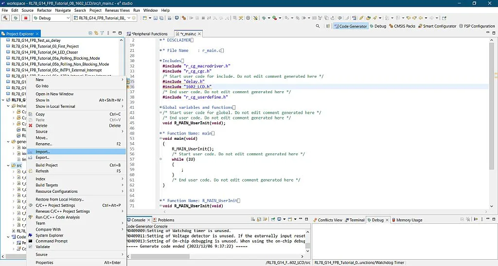
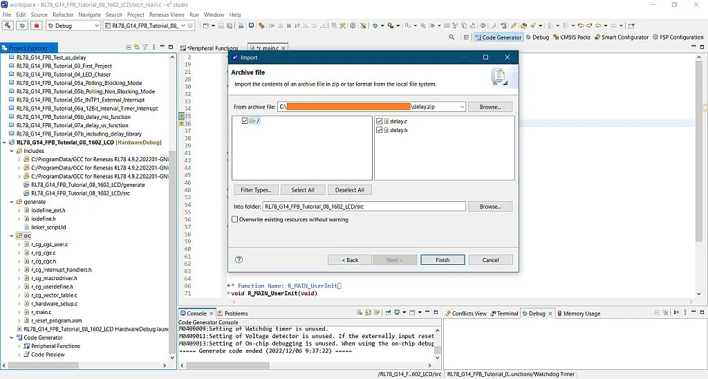
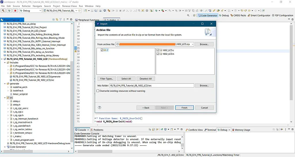

So we’re done importing the libraries. Here’s the sample code:
/***********************************************************************************************************************
* DISCLAIMER
* This software is supplied by Renesas Electronics Corporation and is only intended for use with Renesas products.
* No other uses are authorized. This software is owned by Renesas Electronics Corporation and is protected under all
* applicable laws, including copyright laws.
* THIS SOFTWARE IS PROVIDED "AS IS" AND RENESAS MAKES NO WARRANTIES REGARDING THIS SOFTWARE, WHETHER EXPRESS, IMPLIED
* OR STATUTORY, INCLUDING BUT NOT LIMITED TO WARRANTIES OF MERCHANTABILITY, FITNESS FOR A PARTICULAR PURPOSE AND
* NON-INFRINGEMENT.  ALL SUCH WARRANTIES ARE EXPRESSLY DISCLAIMED.TO THE MAXIMUM EXTENT PERMITTED NOT PROHIBITED BY
* LAW, NEITHER RENESAS ELECTRONICS CORPORATION NOR ANY OF ITS AFFILIATED COMPANIES SHALL BE LIABLE FOR ANY DIRECT,
* INDIRECT, SPECIAL, INCIDENTAL OR CONSEQUENTIAL DAMAGES FOR ANY REASON RELATED TO THIS SOFTWARE, EVEN IF RENESAS OR
* ITS AFFILIATES HAVE BEEN ADVISED OF THE POSSIBILITY OF SUCH DAMAGES.
* Renesas reserves the right, without notice, to make changes to this software and to discontinue the availability
* of this software. By using this software, you agree to the additional terms and conditions found by accessing the
* following link:
* http://www.renesas.com/disclai...
*
* Copyright (C) 2011, 2021 Renesas Electronics Corporation. All rights reserved.
***********************************************************************************************************************/

/***********************************************************************************************************************
* File Name    : r_main.c
* Version      : CodeGenerator for RL78/G14 V2.05.06.02 [08 Nov 2021]
* Device(s)    : R5F104ML
* Tool-Chain   : GCCRL78
* Description  : This file implements main function.
* Creation Date: 06/12/2022
***********************************************************************************************************************/

/***********************************************************************************************************************
Includes
***********************************************************************************************************************/
#include "r_cg_macrodriver.h"
#include "r_cg_cgc.h"
/* Start user code for include. Do not edit comment generated here */
#include "delay.h"
#include "1602_LCD.h"
/* End user code. Do not edit comment generated here */
#include "r_cg_userdefine.h"

/***********************************************************************************************************************
Global variables and functions
***********************************************************************************************************************/
/* Start user code for global. Do not edit comment generated here */
/* End user code. Do not edit comment generated here */
void R_MAIN_UserInit(void);

/***********************************************************************************************************************
* Function Name: main
* Description  : This function implements main function.
* Arguments    : None
* Return Value : None
***********************************************************************************************************************/
void main(void)
{
    R_MAIN_UserInit();
    /* Start user code. Do not edit comment generated here */
    delay_us_TAU_Init();
    lcd_init(0, 0);

    PM5_bit.no2 = 0;

    while (1U)
    {
    	lcd_set_cursor(1, 1);
    	lcd_write("Hello Renesas");
    	lcd_set_cursor(1, 2);
    	lcd_write("from BreadMan :)");
    	P5_bit.no2 = 1;
    	delay_ms(1000);
    	lcd_clear();
    	P5_bit.no2 = 0;
    	delay_ms(1000);
    }
    /* End user code. Do not edit comment generated here */
}


/***********************************************************************************************************************
* Function Name: R_MAIN_UserInit
* Description  : This function adds user code before implementing main function.
* Arguments    : None
* Return Value : None
***********************************************************************************************************************/
void R_MAIN_UserInit(void)
{
    /* Start user code. Do not edit comment generated here */
    EI();
    /* End user code. Do not edit comment generated here */
}

/* Start user code for adding. Do not edit comment generated here */
/* End user code. Do not edit comment generated here */
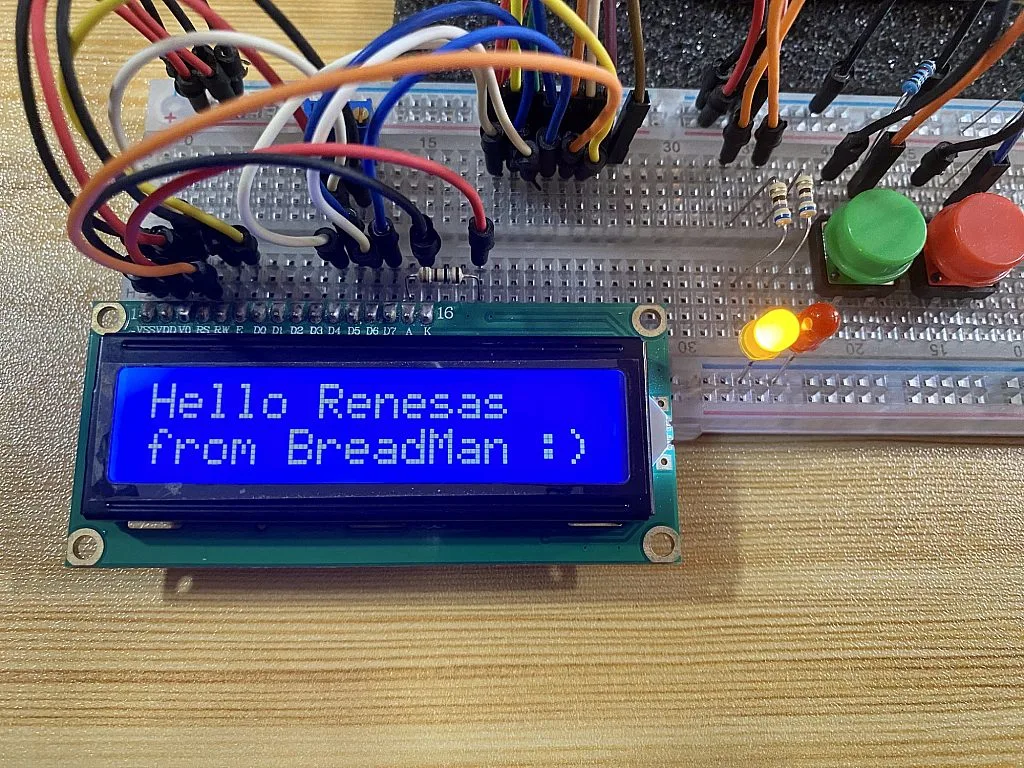
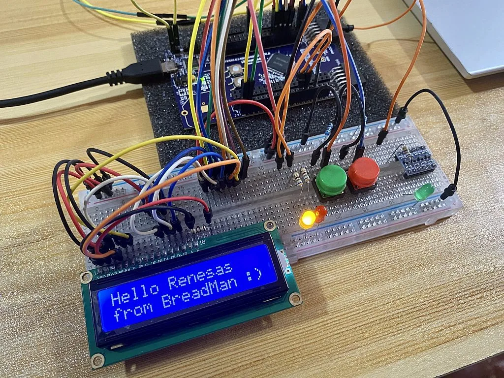
Line 57, line 58, and line 60 initialize the TAU used in the delay_us() function, initialize the LCD, and set pin P52 as an output, respectively. Inside the body of the infinite while loop, we’ll display “Hello Renesas” in row 1 of the 1602 LCD (line 64 to line 65), display “from BreadMan :)” in row 2 (line 66 to line 67), set pin P52 HIGH (line 68), then after a 1-second delay, we will clear the display and set pin P52 LOW (line 69 to line 71). This entire process will be repeated after the 1-second delay in line 72.

You can just copy the code in line 57 to line 73 and paste it inside the main function between the comments generated by the code generator. After that, build the project and upload the code to the RL78/G14 FPB. And here’s the output:
So that’s all for now! I hope you enjoyed this tutorial. Again, if you want to know more about the LCD operation and its functions, please check Sergey’s tutorial here: Embedded C Programming with the PIC18F14K50 - 18. Using 1602 Character LCD with the HD44780 Driver. But if you still have questions, please leave it in the comments section below or you can message us. See you in the tutorial! Advance Happy New Year! :)

Get the latest tools and tutorials, fresh from the toaster.


