Visualize Data with 7-segment LED Indicator | Embedded C Programming - Part 6
Published
Hello again! Despite the hard times, I’m still here, and keep working on tutorials. Because whatever happens, “the show must go on!” So this time we will not consider any new modules of the PIC MCU but will focus on a dynamic indication algorithm. Actually this algorithm is very well known and described a lot of times but I want to create my own. I wanted to write about it in the previous Assembly-based series, but the small number of GPIO pins on the PIC10F200 MCU stopped me. This time we have no such limitation, so let’s do the following task: display a 3-digit number with a 3-digit 7-segment LED indicator (which I will go over in a moment).
We will use this indicator in several next tutorials so this is kind of a preparation work to simplify our life in the future.
The schematic diagram to implement the current task is much more tangled than what we’ve seen previously (Figure 1).

As you may see, it has many more parts. Except for the familiar MCU PIC18F14K50 (DD1) and the PICKit programmer (X1), it consists of the 7-segment indicator (7Seg1) and eight 330 Ohm resistors (R1-R8).
The 7-segment indicator can be any type with the dynamic indication. It’s easy to distinguish them with the static indicators. If the pin number is less than 12, it’s most likely the dynamic indicator, otherwise it’s a static one.
The difference between them is that in a static indicator every LED segment has its own pin (Figure 2, 3) while in a dynamic indicator the segments of the same name are internally connected together and have only one common pin (Figure 4, 5).


So, as you can see in Figure 2, 3, static indicators have one common pin (cathode, Figure 2, or anode, Figure 3) and separate pins for all segments of each digit. While in dynamic indicators (Figure 4, 5) all segments A, B, C etc. of different digits are connected together and have only one pin. Each type has its own cons and pros. Static indicator has a simpler control algorithm but requires more pins to connect. Dynamic indicator requires much less pins to connect but needs a more complex algorithm to show the numbers. For now, the dynamic indicators are much more widespread than static ones because of the easier connection. You can compare the number of required pins for static and dynamic indicators with different digit numbers in Table 1.
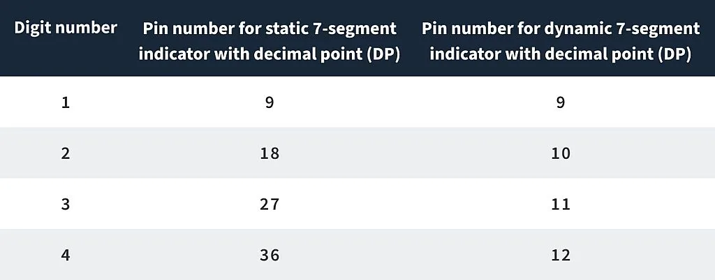
As you can see, the difference becomes more and more significant with an increasing number of digits. And wasting 36 MCU pins just for connecting a 4-digit indicator is not a good idea, obviously very inefficient. Even 12 pins for dynamic indication can be a lot for MCUs with a small pin-count. For such applications one can use the module with the 7-segment LED driver, for instance TM1637, which was described here: Digital Thermometer - Part 16 Microcontroller Basics (PIC10F200).
That is all theory, so let’s return to our schematics diagram (Figure 1) and put it in practice. Frankly, I took the first indicator that I found in my heap of parts. And it was a 3-digit common anode indicator of the 2381BS-1 type. But you can use any one you have. The pinout of them is usually the same. And if you have the common cathode indicator, it’s also fine, I’ll explain how to change the code to use it.
The R1-R8 resistors limit the current that is flowing through the indicator. Their value is not 1 kOhm like we used in the previous tutorials but 330 Ohms. This is because in dynamic indication we switch between the digits at a high frequency, so the average current through each LED is smaller. If we have 3 digits then the current is ⅓ the size and thus we need a resistor with ⅓ the resistance.
The connection of the indicator to the MCU is not random (well, it’s semi-random but let’s talk about it later). The best option is to connect all the segments to one port of the MCU as this will significantly simplify the code. In the PIC18F14K50 MCU, only PORTC has all eight pins, so we will use it.
Within the port, the connection can be random. I connected the indicator in such a way because it was more convenient for me to put the resistors on the breadboard like this. But you can invent your own connection, I’ll also explain how to change the program to use it. Just keep in mind that all segments should be connected to PORTC.
The common digits pins can be connected randomly but I decided to connect them all to PORTB to simplify the initialization. Besides, PORTA is, by default, used by other MCU modules so it’s better to keep it untouched while possible.
OK, that’s all about the connection. Let’s now briefly talk about the dynamic indication algorithm. It’s not hard actually. As all segments of the same name are connected together, if we apply the voltage to all common pins at once, the same segment will light on in all positions simultaneously, which is not good if we want to display different digits in different positions. Thus to display different digits in different positions we need to switch between them quickly. The human eye doesn’t see flickering if the switching frequency is higher than 50 Hz. So we need to do the following:
- At the start of a loop turn off all digits (apply low voltage to all common pins for common anode indicators, or high voltage to all common pins for common cathode indicators)
- Apply the correct voltage (low for common anode indicators, or high for common cathode indicators) to the segments which form the digits we want to display.
- Turn on the corresponding digit position by applying high voltage for common anode indicator, or low voltage for common cathode indicator to the corresponding common pin.
- Perform a short delay (about 5ms) to let the digit be turned on for this time.
- Select the next digit position and return to step 1.
The first step is needed to avoid so-called shadows when the previous digit is dimly displayed in the next position.
OK, as we now have all theoretical background, let’s consider the program code. This time I will not include the configuration bits here as they are the same as the previous times.
#define _XTAL_FREQ 1000000            //CPU clock frequency


#include <xc.h>            //Include general header file


#define A   0b00001000            //Segment A is connected to RC3
#define B   0b10000000            //Segment B is connected to RC7

#define C   0b00000010            //Segment C is connected to RC1
#define D   0b00010000            //Segment D is connected to RC4
#define E   0b00100000            //Segment E is connected to RC5
#define F   0b01000000            //Segment F is connected to RC6
#define G   0b00000100            //Segment G is connected to RC2
#define DP  0b00000001            //Segment DP is connected to RC0


const uint8_t digit_gen[10] =        //Digits generator
{
             ~(A+B+C+D+E+F),         //0
             ~(B+C),                 //1
             ~(A+B+G+E+D),           //2
             ~(A+B+C+D+G),           //3
             ~(F+G+B+C),             //4
             ~(A+F+G+C+D),           //5
             ~(A+F+E+D+C+G),         //6
             ~(A+B+C),               //7
             ~(A+B+C+D+E+F+G),       //8
             ~(D+C+B+A+F+G).         //9
};


uint16_t number = 678;             //Number to display
uint8_t digit;                     //Digit number that is currently displayed


void main(void)                    //Main function of the program
{
             TRISC = 0;            //Configure RC port as output
             TRISB = 0;            //Configure RB port as output
             LATC = 0xFF;          //Set all RC pins high
             while (1)             //Main loop of the program
             {
             LATB = 0;          //Set all RB pins low to shutdown all the segments
             switch (digit).    //Which digit to display
             {
             case 0:            //If digit 1
                         LATC = digit_gen[number / 100];           //Display the hundreds
                         LATBbits.LB7 = 1;            //Turn on RB7 to which digit1 is connected
                         break;
             case 1:           //If digit 2
                         LATC = digit_gen[(number % 100) / 10];            //Display the tens
                         LATBbits.LB6 = 1;           //Turn on RB6 to which digit2 is connected
                         break;
             case 2:           //If digit 3
                         LATC = digit_gen[number % 10];           //Display the ones
                         LATBbits.LB5 = 1;           //Turn on RB5 to which digit3 is connected
                         break;
             }
             __delay_ms(5);                         //Perform the delay to let the segment be on for some time
             digit ++;          //Select next digit
             if (digit > 2)     //If digit number is higher than 2
             digit = 0;         //Then set the digit as 0
             }
}
We’ll start considering the code with line 5 as the previous lines were described in previous tutorials.
In lines 5 to 12 we define the LED indicator segments connection to PORTC of the MCU. Let’s consider one of the lines in more detail, for example line 5:
#define A 0b00001000
Here we define a macro called A which represents the segment A of the indicator (Figure 1). It is connected to pin RC3 of the MCU. To operate with this pin we have to change bit #3 of the PORTC, LATC, TRISC registers. The 0b in 0b00001000 means that the number is written in binary (the MSB first). So 0b00001000 represents the 8-bit (or one byte) number in which only bit #3 is 1. This record is equivalent to the 0x08 (hexadecimal format) or just 8 (decimal format) but the binary format is the most descriptive and intuitive in this case.
As you can see, all other segment definitions (lines 6-12) have the same structure - all numbers have only one bit set to 1, which corresponds to the pin to which the certain segment of the indicator is connected. Segment DP (line 12) stands for decimal point, we will not use it in our current program but it’s better to have it for the future.
Warning! If you varied your connections to the MCU, you need to redefine the values in lines 5-12 according to your schematics diagram.
In line 14 to 26 there is a digits generator. We define the constant array of the type uint8_t which means unsigned 8-bit type (equal to “unsigned char”) with the name “digit_gen”. This array consists of 10 elements - one for each decimal digit from 0 to 9. They are described in lines 16-25. Again, let’s consider only line 16 in more detail, because the rest are the same.
~(A+B+C+D+E+F)
This record is the first element of an array. As you know, the array indexes in C language start with 0. So this line will form the digit “0” on the indicator. If you look at Figure 1, you can see that to form it, you need to light segments A, B, C, D, E, and F. Earlier, we defined all these segments. So when we sum the values of A, B, C, D, E, and F macros, we will get the 8-bit number in which only the bits corresponding to these segments will be 1. In our case the value of the expression A+B+C+D+E+F will be 0b11111010. But I have the common anode indicator (Figure 5) so to light on the segment I need to apply the high voltage to the common pin and low voltage to the segment pin. That’s why I need to invert this value. The “~” operation means the bitwise inversion of the expression. So, after implementing the expression ~(A+B+C+D+E+F) we will have the value 0b00000101. And when we apply the high voltage to the common pin, the segments A, B, C, D, E, and F will be lit up, forming the “0” digit.
Warning! If you use the common cathode indicator, you need to apply the low voltage to the common pin, and high voltage to the segment pins, thus in this case you don’t need to invert the expression, so just eliminate the “~” sign in lines 16-25.
In line 28, we define the variable of “uint16_t” type which represents the unsigned 16-bit number, called “number”. This is the number we want to display in the indicator. You can write any value here. I wrote “678” just for example.
In line 29, we define the variable “digit” which represents the number of the digit position which is currently lit up. Please pay attention, that I will start counting from 0 as it is customary in C language. So the “digit” value of 0 will correspond to the first position, the value of “1” will correspond to the second position and so on and so forth.
That is all the definitions required, so in line 31 the main function of the program starts.
In line 33, we configure all of PORTC as outputs by resetting the value of the TISC register.
In line 34, we do the same with PORT. Actually, we only need to use the pins RB5, RB6, and RB7. But pins RB0-RB3 are absent in this controller anyway, and pin RB4 can be used to connect the fourth digit if you use the 4-digit indicator. So configuring all of PORTB as outputs won’t hurt.
In line 35, we set all pins of PORTC high to turn off all the segments (Warning! If you use a common cathode indicator, you need to set all the pins low by writing LATC = 0 in this line).
And that’s all the configuration we need. We can now implement the main endless loop of the program in which we will perform the algorithm I described earlier (lines 36-58).
In line 38, we set all pins of the port B low to turn off all the segments by writing LATB = 0 (Warning! If you use the common cathode indicator, you need to set all the pins high by writing LATB = 0xFF).
Then in lines 39-53 there is a “switch” construction which allows it to perform the branches for several values of the variable. In our case, we will check the variable “digit” and light the corresponding position with the required digit. But first let me describe the algorithm of splitting the number into digits. It’s a bit different from what I explained in the PIC10F200 tutorials. This algorithm can be applied when we know exactly the length of the number we want to split. In our case this length is 3 digits. So we need to split the number into hundreds, tens, and ones.
To get the hundreds value we just divide the number by 100. As this is the integer division, it will just truncate the modulo and leave the required digit. In our case:
678 / 100 = 6 (integer division)
Getting the tens value is a bit more complex. First, we need to get the modulo of division of the number by 100, and then divide the obtained result by 10:
678 % 100 = 78 (modulo)
78 / 10 = 7 (integer division)
Getting the ones is quite simple. We just need to get the modulo of the division of the number by 10:
678 % 10 = 8 (modulo)
To see how this can expand, let me show this algorithm for a 4-digit number:
thousands: number / 1000
hundreds: (number % 1000) / 100
tens: (number % 100) / 10
ones: number % 10
And now let’s return to our program. In lines 41-44, we process the first position of the indicator (when “digit” = 0). In this case, we write into the LATC register the digits generator array value with the index that corresponds to the hundreds of the number (line 42):
LATC = digit_gen[number / 100]
Thus, the shape of the required digit will be loaded into the LATC register. Now we only need to apply the high level to the pin RB7 to light up the first position (line 43). (Warning! If you use the common cathode indicator, you need to apply the low level to the RB7 pin by writing LATBbits.LB7 = 0).
Displaying the tens (line 45-48) and ones (lines 49-52) are the same, you just load the digits that correspond to tens and ones into the LATC register and apply the high (or low if you use the indicator with the common cathode) level to the required RBx pin.
In line 54, we perform the short delay of 5 ms. In this case the general delay for three digits will be 15ms which gives the frequency of 1 / 0.015 = 67 Hz. This is higher than 50 Hz, so we will not notice the flickering. Also, I don’t recommend making the delay too short as this will make the digits dimmer.
In line 55, we increment the “digit” variable to select the next digit position for the next loop iteration. Then we check if the value becomes higher than 2 (line 56). As the only accepted values are 0, 1, and 2 (if you use a 4-digit indicator, then the value 3 is also accepted) then we reset the value of the “digit” to 0 when its value is higher than 2.
And that’s all for now. This time we didn’t learn anything new about the MCU itself but we have discovered the algorithm of the implementation of the dynamic indication. Next time, I’ll show how to make the dynamic indication using MCC. We will consider that we are so lazy, that we don’t want to know anything about the MCU registers and will use only the API functions. There’s nothing wrong with this.
As homework, I want you to add a button to the schematics (you can connect it to the RB6 pin like we did in the previous tutorial, and reconnect the indicator’s digit2 pin to the RB4), count the number of presses of the button and display it on the indicator.

Authored By
Sergey Sokol
I was born, raised, and currently live in Ukraine. I’m fond of different types of electronics and backpacking but these things have been set aside with the war that has been thrust on my country, my people, and my family. Through these trials, if you could help support me financially, I would appreciate any help that could be sent via Paypal to sokolsp@gmail.com

Related Tutorials

Related EE FAQs
 work?")
How do Analog to Digital Converters (ADCs) work?

Answered by Uma Bharathi D

What's the difference between a regular relay and a power relay?

Answered by Jayesh Upadhyay

What is a PWM signal?
Answered by Jayesh Upadhyay

Why is RAM faster than other memories?
Answered by Jayesh Upadhyay
Explore CircuitBread
- 244 Tutorials
- 9 Textbooks
- 12 Study Guides
- 31 Tools
- 104 EE FAQs
- 295 Equations Library
- 213 Reference Materials
- 97 Glossary of Terms
Friends of CircuitBread
-

Free Industry Lead Time Monitor
-

Product Samples Available by Request
-

Relays, Switches & Connectors Knowledge Series


Get the latest tools and tutorials, fresh from the toaster.


