Integrating Buttons With a Microcontroller Using MCC | Embedded C Programming - Part 5
Published
Hi again! In this tutorial I will show you how to implement the same task as in the previous one (to toggle the LED state every time when the button is pressed) but using the MPLAB Code Configurator (MCC). I will consider that you are already familiar with this tutorial https://www.circuitbread.com/tutorials/embedded-c-programming-with-the-pic18f14k50-3-introduction-to-the-mplab-code-configurator-mcc and know the basics of the MCC.
The schematic diagram hasn't changed since the last time and is shown in figure 1.

Now let’s create a new project and click on the “MCC” icon in the toolbar to start the MPLAB Code Configurator. Go through the MCC Content Manager Wizard, change the package type from QFN20 to the one you have, change the System Module settings to be the same as in our intro to the MCC tutorial, ignore the Interrupt Module, and open the Pin Module - we will mainly work with it.
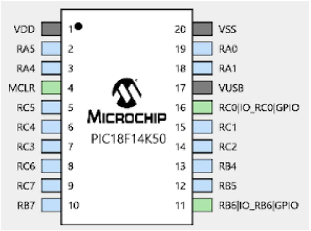
The same as in the last MCC tutorial, right click on the RC0 pin and select “Pin Module | GPIO | output”. As follows from figure 1, this is the pin to which the LED is connected. Then right click on the RB6 pin and select “Pin Module | GPIO | input”, because button S1 is connected to it (figure 2).

Then in the Pin Module table you will see the two new lines (figure 3).

In the Custom Name column we can change the names of the pins. Let’s call the RC0 pin “LED”, and the RB6 pin “BUTTON”.
Let’s now make sure that the pins are configured correctly. Configuration of the RC0 pin is the same as in the previous tutorial. You only need to set the check mark at the “Output” column. For the RB6 pin the “Output” field should be clear as RB6 is configured as an input. Also, you need to enable the pull-up resistor on the RB6 pin. To do this you need to set the check mark at the “WPU” column. WPU means “weak pull-up”. Like the PIC10F200, the PIC18F14K50 MCU has internal pull-up resistors on several pins. If you don’t know what pull-up resistors are, you can refer to this tutorial where I explained what they are, and why we need them: https://www.circuitbread.com/tutorials/button-inputs-part-9-microcontroller-basics-pic10f200.
So after all the changes your table should look like this (figure 4).

And now we’re done with the configuration, all that is needed is to generate the code by clicking on the “Generate” button in the Resource Management area.
Now we can return to the “Projects” tab in the left top part of the screen, and find the “main.c” file we just generated in the “Source files” folder of the project. We can leave the comments in the file unchanged or we can delete them to reduce the file size, it doesn’t matter. I will delete the unnecessary lines and leave only the code.
#include "mcc_generated_files/mcc.h"

void main(void)
{
	// Initialize the device
	SYSTEM_Initialize();
	while (1)
	{
    	if (BUTTON_GetValue() == 0) //If button is pressed
    	{
        	__delay_ms(20); 	//Then perform the debounce delay
        	if (BUTTON_GetValue() == 0) //If after the delay button is still pressed
        	{
            	while (BUTTON_GetValue() == 0); //Then wait while button is pressed
            	__delay_ms(20);  //After button has been released, perform another delay
            	if (BUTTON_GetValue() == 1) //If the button is released after the delay
            	{
                	LED_Toggle();//Then perform the required action (toggle the LED)
            	}
        	}
    	}
	}
}
The lines added by me are lines 9-21, highlighted with the green color. All the other, non-highlighted lines were described in this tutorial, so I’ll start with the first green line #9.
The algorithm of the button processing was described in this tutorial: https://www.circuitbread.com/tutorials/button-inputs-part-9-microcontroller-basics-pic10f200 but I’ll repeat it briefly with the C language.
In line 9, we check if the BUTTON pin (which is RB6 as you remember) is 0. If the button is not pressed, then the pin state will be 1 because of the pull-up resistor. When we press the button, which is connected to ground, the state of the pin will become 0. So, in line 9 we check if the button is pressed. The name of the macro BUTTON_GetValue() was taken from the file “pin_manager.h” and allows you to read the actual state of the pin.
After registering the first moment when the button was pressed, we perform the debounce delay of 20 ms (line 11). If the button isn’t very good quality, then the debounce delay time may be increased. After this time we check one more time if the button is still pressed (line 12). If it is (which means that it was not a false signal) then we wait the entire time while the button is pressed and just do nothing. This is implemented by means of the while loop (line 14). When the loop condition becomes false, which means that the button has been released, then we perform another debounce delay (line 15). After that we check if the pin BUTTON is high (line 16). If it is, that means the button has truly been released. And only after that do we perform the required action. In our case, it’s toggling the LED (line 18) but this can be any action you need. The macro LED_Toggle() was already discussed in this tutorial, so I won't stop here.
Now you can assemble the circuit according to Fig. 1, compile the code, and download it into the MCU. If everything is done correctly, the LED will change its state every time you press the button. If the operation is not consistent, try to increase the debounce delay. If nothing works at all, double check the connection.
As homework, change the program to blink the LED with the frequency of 4 Hz while the button is pressed. After releasing the button, turn off the LED.
Hope to see you soon despite these hard and unpredictable times.

Get the latest tools and tutorials, fresh from the toaster.


