How to Use External Interrupts on a Microcontroller | Renesas RA - 5
Published
Hello! We will now continue studying the RA MCUs and the FSP configurator. This time, we will add a new stack to the FSP and configure it. Initially, I was thinking that we can try to do something complex like a USB device because Renesas claims that the FSP visual configurator makes the code really simple but then I decided not to rush things and increase complexity step-by-step instead. So today’s task is quite simple: upon pressing the button “USR BTN” we will toggle the LED1 state. To make the task more interesting, let’s process the button pressing in the interrupt subroutine.
Disclaimer. The approach that will be shown in this example is not optimal from a programming perspective and is not recommended to use in real devices, its goal is just to show how to configure the external interrupt using the FSP.
Let’s open e2 studio and create a new RA project called “Button” as I described in this tutorial. The only difference is in step “Project Template Selection”. This time we need to select the “Bare Metal - Minimal” (Figure 1), as we will add the required FSP stack and code manually.

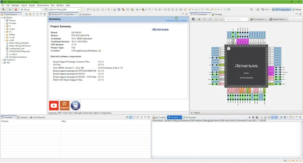
Finally you should see the familiar window with the FSP Summary in the middle and the MCU view in the right (Figure 2).
As follows from the task, we need to process the pressing of the “USR BTN” S1. To do this we first need to figure out which pin of the MCU it is connected to. There are several ways to do this. First, you can download and open the development board user’s manual from the Renesas site, and find the required information there. Second, you can look on the back of your board and read the text opposite to the button S1 - “P206 User SW”. Either method will yield the same result - the button is connected to pin P206.
I think some words are required about the pin naming convention in RA MCUs. The first number represents the port number, and the last two numbers represent the pin number within the port. Each port can have up to 16 pins. So pin P206 is the sixth pin of port P2.
Now, as we know which pin we need, let’s find it in the “FSP visualization” window, and right click on it (Figure 3). To zoom in or zoom out of the MCU view, you can use the mouse wheel.

As you see, there are a lot of functions that this pin can implement but we need the external interrupt. The common abbreviation for interrupts is IRQ (Interrupt ReQuest), so let’s select line IRQ6.
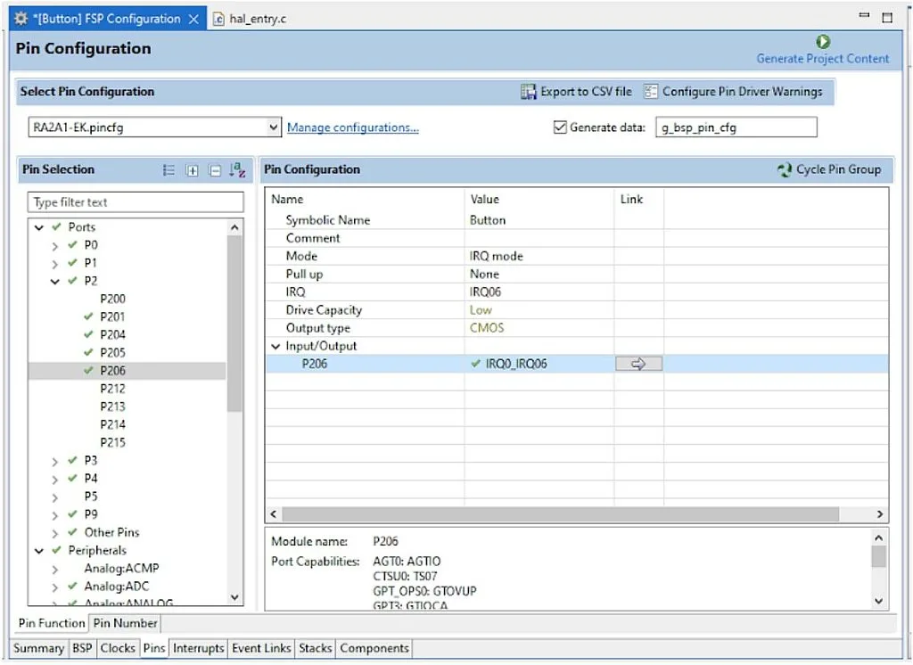
Now, let’s switch to the “Pins” tab of the “FSP Configurator” window, open the “P2” drop-down list and select the P206 line (Figure 4).
This is something similar to the MCC PIC configurator which I talked about in the “MCC Based Embedded C Programming with the PIC18F14K50” series on the circuitbread.com site.
Let’s consider this table in more detail.
- “Symbolic name” is the custom name of the pin. I have called it “Button” as this reflects its functionality. This field is optional.
- “Comment” is the custom optional comment to the pin.
- “Mode” is the pin mode: Input, Output, IRQ, other peripheral modules, etc.
- “Pull-up” allows to enable or disable the pull-up resistor at the corresponding pin. Usually we enable it when we work with buttons but according to the EK-RA2A1 User’s Manual (Figure 5) there is external pull-up resistor R3, so in this current case we don’t need to enable it.

- “IRQ” shows the external interrupt number for this pin. In our case it’s IRQ06.
- “Drive capacity” sets the output current on certain pins. It can be low (up to 40 mA at 5.5V, up to 18 mA at 3.3V), and medium/middle (up to 100 mA at 5.5V, up to 40 mA at 3.3V). Some pins have only low drive capacity, so this value can’t be changed, also P407-P409 pins have increased drive capacity (up to 160 mA at 5.5V, up to 70 mA at 3.3V).
- “Output type” sets the type of the output: “CMOS” (push-pull) or “n-channel open-drain”. The second option is only available on some pins.
If you click on the arrow in the “Link” column, you will move to the Peripheral-sorted view (Figure 6).
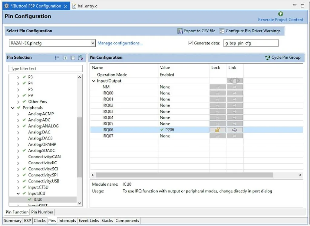
ICU stands for “Interrupt Controller Unit”. This unit, as follows from the RA2A1 Group User’s Manual, “controls which event signals are linked to the Nested Vector Interrupt Controller (NVIC) and Data Transfer Control (DTC) modules. The ICU also controls non-maskable interrupts.”
As follows from Figure 6 the IRQ06 interrupt is linked with the P206 pin. Here, in column “Lock” you can lock this link, so it can’t be changed in the program. In our case it doesn’t matter, as we’re not going to break this connection but it can be useful if you want to add an extra level of protection so that the association between the pin and the interrupt doesn’t go away for any reason.
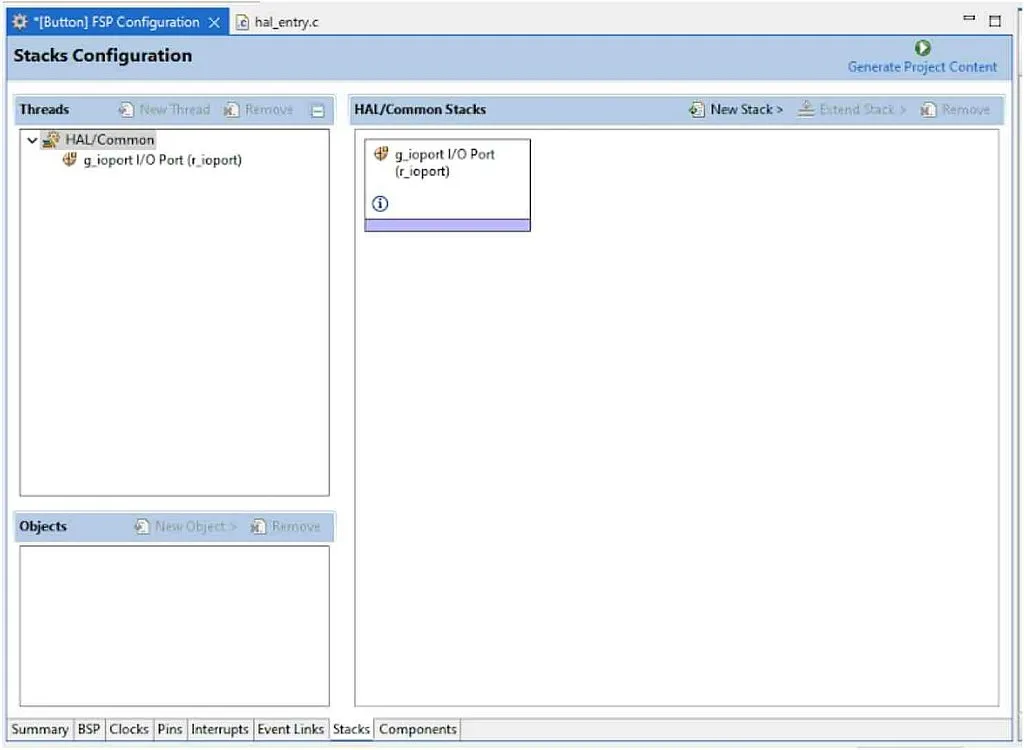
Now, as we configured the pin as the interrupt source, we need to add the stack that will process the interrupt. So let’s open the “Stacks” tab and see that the “g_ioport I/O Port” stack is already added as it’s the basic one that is always used (Figure 7).
Now, we need to click on the “New Stack >” button, find the “Input” line, and select the “External IRQ (r_icu)” point (Figure 8).
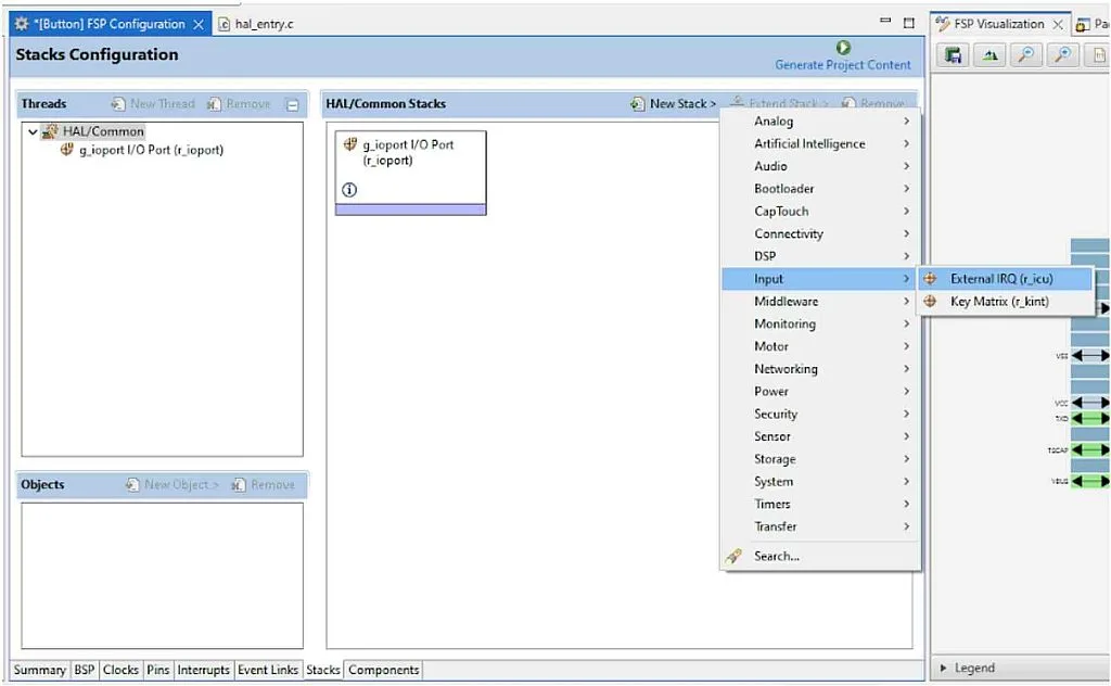
Now, when we click on the newly appeared stack “g_external_irq0”, you can see that its options have appeared in the “Properties” window in the left bottom corner. You should change them according to Figure 9.
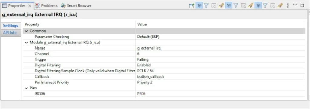
- “Parameter checking” option allows checking the functions arguments when it’s possible. Enabling this option makes code more safe but increases the program size - inversely, disabling it reduces the code size. By default this parameter is set globally in the properties of the “BSP” tab (FYI, it’s disabled there) but you can individually enable or disable it for each stack. Let’s leave it unchanged.
- “Name” is the name of the instance of this stack in the program. By default it was “g_external_irq0” but I removed the “0” as we use only one external IRQ.
- “Channel” is the channel number of the IRQ. As we considered before, P206 can be used as IRQ6, so we need to write the “6” here.
- “Trigger” sets the condition of generation the interrupt: rising, falling or both edges, or permanently while low level is present on the pin. As we need to catch the moment when the button is pressed, we set this parameter as “Falling”.
- “Digital filtering” allows the user to enable or disable digital filtering. When enabled, this filter checks if the interrupt condition happens for 3 periods of the frequency, set by the next field “Digital filtering sample clock”. And only in this case the interrupt occurs. Well, it’s an interesting option, why not enable it?
- “Digital filtering sample clock” sets the frequency used by the digital filter. In our case we use the PCLK/64. If you look at the “Clocks” tab, you can see that there are two PCLK frequencies: PCLKB 24 MHz, and PCLKD 48 MHz. In this case PCLKB is used as follows from the hardware manual. So the digital filtering sample clock frequency is 24 MHz / 64 = 375 kHz, and the interrupt will happen if the signal is present for (1 / 375) x 3 = 0.008 ms = 8 us. Well, that’s really not enough for debounce removal, so we will use the regular debounce processing routine.
- “Callback” is the name of the callback function which we will use to process the external interrupt. You can write any name here. I selected the “button_callback”.
- “Pin Interrupt Priority”, as follows from its name, sets the priority of this interrupt. It can be 0 to 3 where the smaller number corresponds to the higher priority. Let’s leave the default value “Priority 2”.
- “Pins” allows us to set the pins which will cause this interrupt. We already set the R206 pin, so no need to change anything here.
Now, let’s switch to the “Interrupts” tab and make sure that the current interrupt has appeared there (Figure 10).
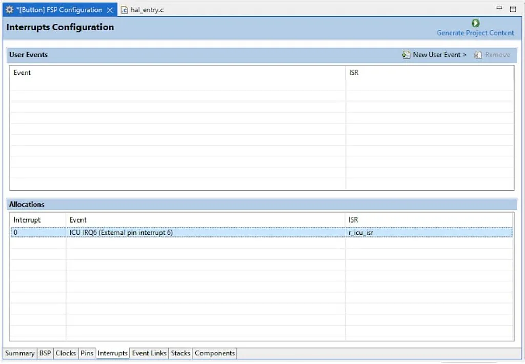
There is nothing to change here, just make sure that the ICU IRQ6 is present in this list and has the ISR name “r_icu_isr”.
That’s actually all we can do in the FSP configurator, the rest of the job we need to do manually by writing code. Let’s press the “Generate Project Content” button in the top right corner of the “FSP Configuration” window. Actually, nothing noticeable will happen but if there are no errors, you can be sure that the code is generated.
Now let’s open the “hal_entry.c” file and write some code there.
#include "hal_data.h"

#define DEBOUNCE_DELAY	20    	//Button debounce delay in ms
extern bsp_leds_t g_bsp_leds;   //Structure with LED information in this board
bsp_io_level_t pin_level;       	//The output level on the LED pin
bsp_leds_t leds;                	//Variable with the LEDs located on the board


FSP_CPP_HEADER
void R_BSP_WarmStart(bsp_warm_start_event_t event);
FSP_CPP_FOOTER


void button_callback(external_irq_callback_args_t *p_args)
{
     FSP_PARAMETER_NOT_USED(p_args);
     if (R_BSP_PinRead(BSP_IO_PORT_02_PIN_06) == BSP_IO_LEVEL_LOW) //If button is pressed
     {
    	R_BSP_SoftwareDelay(DEBOUNCE_DELAY, BSP_DELAY_UNITS_MILLISECONDS); //Debounce delay
    	if (R_BSP_PinRead(BSP_IO_PORT_02_PIN_06) == BSP_IO_LEVEL_LOW)   //If button is still pressed
    	{
        	     while (R_BSP_PinRead(BSP_IO_PORT_02_PIN_06) == BSP_IO_LEVEL_LOW);//Wait while button is pressed
        	     R_BSP_SoftwareDelay(DEBOUNCE_DELAY, BSP_DELAY_UNITS_MILLISECONDS);//Debounce delay
        	     if (R_BSP_PinRead(BSP_IO_PORT_02_PIN_06) == BSP_IO_LEVEL_HIGH) //If button is released
        	     {
           	          pin_level ^= BSP_IO_LEVEL_HIGH;//Toggle LED pin level
           	          R_BSP_PinAccessEnable(); 	//Enable access to the PFS registers
           	          R_BSP_PinWrite(leds.p_leds[0], pin_level);//Write the pin_level to actual LED pin
           	          R_BSP_PinAccessDisable();	//Disable access to the PFS registers
        	     }
    	}
     }
}

/*******************************************************************************************************************//**
 * main() is generated by the RA Configuration editor and is used to generate threads if an RTOS is used.  This function
* is called by main() when no RTOS is used.
 **********************************************************************************************************************/
void hal_entry(void)
{
	/* TODO: add your own code here */

	leds = g_bsp_leds;          	//The LEDs located on the board
	pin_level = BSP_IO_LEVEL_LOW;   //Set the LED output level low
	R_ICU_ExternalIrqOpen(&g_external_irq_ctrl, &g_external_irq_cfg); //Initialization of the external interrupt
	R_ICU_ExternalIrqEnable(&g_external_irq_ctrl); //Enabling the external interrupt

	while (1) {}

#if BSP_TZ_SECURE_BUILD
	/* Enter non-secure code */
	R_BSP_NonSecureEnter();
#endif
}


/*******************************************************************************************************************//**
 * This function is called at various points during the startup process.  This implementation uses the event that is
 * called right before main() to set up the pins.
 *
 * @param[in]  event	Where at in the start up process the code is currently at
 **********************************************************************************************************************/
void R_BSP_WarmStart(bsp_warm_start_event_t event)
{
     if (BSP_WARM_START_RESET == event)
     {
#if BSP_FEATURE_FLASH_LP_VERSION != 0

    	/* Enable reading from data flash. */
    	R_FACI_LP->DFLCTL = 1U;

    	/* Would normally have to wait tDSTOP(6us) for data flash recovery. Placing the enable here, before clock and
     	* C runtime initialization, should negate the need for a delay since the initialization will typically take more than 6us. */
#endif
     }

     if (BSP_WARM_START_POST_C == event)
     {
         /* C runtime environment and system clocks are setup. */

         /* Configure pins. */
         R_IOPORT_Open (&g_ioport_ctrl, g_ioport.p_cfg);
     }
}


#if BSP_TZ_SECURE_BUILD

BSP_CMSE_NONSECURE_ENTRY void template_nonsecure_callable ();

/* Trustzone Secure Projects require at least one nonsecure callable function in order to build (Remove this if it is not required to build). */
BSP_CMSE_NONSECURE_ENTRY void template_nonsecure_callable ()
{


}
#endif
I’ve marked the code that I added with green. The rest of the auto-generated code we have considered briefly in this tutorial. So let’s consider only the lines that we added manually. At this point, you may be very confused and wonder where I figured out what format and style I used with certain commands, don’t worry, I’ll review my not-so-secret resources as I get to the commands.
In line 3 we define the DEBOUNCE_DELAY macro and assign the value of 20 to it. This is the debounce time of the button S1. The quality of the button seems to be quite high, so 20 ms will be more than sufficient.
In line 4 we define the variable g_bsp_leds of type bsp_leds_t. The extern modifier tells the compiler that this variable is defined in another place. And really, it’s declared in the file “board_leds.c” which is located in the “ra\board\ra2a1_ek” folder. This variable is the structure that consists of the all LEDs of the board, and is defined as:
const bsp_leds_t g_bsp_leds =
{
	.led_count = (uint16_t) ((sizeof(g_bsp_prv_leds) / sizeof(g_bsp_prv_leds[0]))),
	.p_leds	= &g_bsp_prv_leds[0]
};
where g_bsp_prv_leds is defined in the same file before:
static const uint16_t g_bsp_prv_leds[] =
{
	(uint16_t) BSP_IO_PORT_02_PIN_05, ///< LED1
};
As our board has only one user LED, connected to pin P205 as follows from the last declaration, the led_count field will be 1, and the p_leds field will point to the BSP_IO_PORT_02_PIN_05 pin.
In line 5 we declare the variable pin_level of type bsp_io_level_t. This type has two values, as follows from its declaration:
typedef enum e_bsp_io_level
{
	BSP_IO_LEVEL_LOW = 0,          	///< Low
	BSP_IO_LEVEL_HIGH              	///< High
} bsp_io_level_t;
Actually, we could just use values 0 and 1 but this type makes the text more readable though much longer.
Finally, in line 6 we define the variable leds of type bsp_leds_t. Actually I don’t know why we need it but in the “Blinky” example it was done like this.
Please note that the types and macro definitions names correspond to the FSP naming paradigm described here.
Let’s now switch to the hal_entry function which replaces the main function in a normal program. There is even a hint where to write the user code (line 39). Let’s follow it.
In line 41 we assign the g_bsp_leds value to the leds variable. As I said before, this was taken from the “Blinky” example, I’d just use the g_bsp_leds variable without adding new essences.
In line 42 we set the pin_level as BSP_IO_LEVEL_LOW to indicate that the initial LED level is low.
In line 43 we open the external interrupt instance g_external_irq_ctrl, and assign it with the settings g_external_irq_cfg. These settings are based on the values that we set in the FSP configurator (Figure 9). In line 44 we enable the external interrupt with the specified settings.
One can ask where I found these names and these functions. It’s quite easy.
In the “Stacks” tab each block has the sign. When you click on it, the web-page with the information about the corresponding block will open. It has complete information about api functions, macros and variables used.
Also there are some code examples, for example, shown in Figure 11.

As you can see, it has both functions present in lines 43-44. As for the variables names, their prefix “g_external_irq” is the same as we wrote in the field “Name” in the stack properties (Figure 9). So, as you can see, if you know where to look, you can find everything relatively easily.
As follows from Figure 11, these two lines are enough to configure and start the external interrupt. When it happens, the callback function “button_callback” will be invoked because we called it this in Figure 9. This function is not created automatically, so you should create it manually. In our case it’s located on lines 12-31.
Please note, that everything we need to do in this program is done in this callback function, so the main loop of the program is empty (line 46). As I said in the very beginning, it’s a very, very bad approach because we use a blocking button processing method inside the interrupt subroutine, and the good manners rules say that the interrupt subroutine should take as little time as possible. In the current case I have the excuse that there is only one interrupt in the program, and nothing else is done here.
So let’s consider this external interrupt callback. This function receives the argument p_args of type external_irq_callback_args_t*. Where did I find it? Well, it was hidden but I managed (and, frankly, the manuals helped me as well).
There is a very helpful thing called “Developer Assistance”. It’s located in the Project Explorer as the last line of the project. If you expand it, you can see all stacks added in the program.
When you expand any of them, you can see the description and syntax of all functions related to these stacks, including the “Callback function definition” (Figure 12).
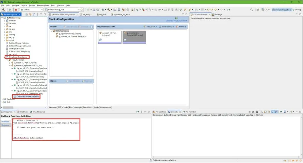
So don’t neglect it, as it may really help you.
Let’s consider the type external_irq_callback_args_t, it’s quite interesting. It’s defined in the file “r_external_irq_api.h”.
typedef struct st_external_irq_callback_args
{
	/** Placeholder for user data. Set in @ref external_irq_api_t::open function in @ref external_irq_cfg_t. */
	void const * p_context;
	uint32_t 	channel;          	///< The physical hardware channel that caused the interrupt.
} external_irq_callback_args_t;
As you can see, it has two parameters: p_context which, as follows from the comment before its definition, is the user data which can be passed to the callback function. This data is part of the g_external_irq_cfg structure, and is assigned to the interrupt callback in the R_ICU_ExternalIrqOpen function. The second parameter is the IRQ channel that caused the interrupt. If we assign the same callback to several IRQ channels, we can distinguish them using the channel field.
As we’re not using the p_args argument, we invoke the FSP_PARAMETER_NOT_USED macro (line 14) which prevents the compiler warning about unused arguments. If you’re fine with extra warnings, you don’t need to use this line.
Let’s now consider the button processing procedure. It’s quite standard. First, we check the state of P206 (line 15). Function R_BSP_PinRead was found in the same Developer Assistant, but for the g_ioport stack. The value BSP_IO_PORT_02_PIN_06 was written as an analogy to the definition of the LED1 pin:
(uint16_t) BSP_IO_PORT_02_PIN_05, ///< LED1
I assumed that this is the standard form of the pin name syntax, and as you see, I was right.
So if the button pin state is low (which means that the button is pressed), we perform the debounce delay (line 17). We already met the function R_BSP_SoftwareDelay in the “Blinky” example, and considered it in detail in this tutorial.
After the debounce delay we check the button state again (line 18). If it’s still low then we wait while it’s low (line 20). When the button state becomes high, we leave the loop in line 20. Then we perform another debounce delay (line 21) and after that check if the button state is high (line 22). In this case we consider that we have released the button, and now can implement the required action. First, we toggle the pin_level variable by means of the XOR operation between it and the BSP_IO_LEVEL_HIGH constant (line 24). In line 25 we enable access to the PFS register which allows us to configure the pin and to change its state. Actually, as I get, we can enable this access in the initialization part of the program and not care about it anymore but such an approach makes operations with IO ports more secure and prevents them from random changes. In line 26 we assign the pin_level to the leds.p_leds[0] pin (this line was also met in the “Blinky” example). And in line 27 we finally disable access to the PFS register.
And that’s it about the program code. Now you can connect your board to the USB port of the PC, create the debug configuration and run the debug. When you press the button S1, the LED1 should change its state, which means that our program works correctly.
As homework, try to change the logic of the LED1 operation: while the button is pressed, blink the LED1 with a frequency of 2 Hz, and when the button is released, turn off the LED1. As this task requires two button changes (from high to low, and from low to high), use another IRQ Trigger, and try to get rid of the doing all operations inside the callback function.

Get the latest tools and tutorials, fresh from the toaster.


