Controlling LED Brightness Using Touch Button & PWM Module | Renesas RA - 6
Published
Hi again! In the previous tutorial we learned how to use the visual FSP configurator and created a simple application that uses the external interrupt to control the button state. I assumed that it’s better to first use the components that are present onboard the EK-RA2A1 evlauation board. So my sight fell on the capacitive touch button TS1 that is located next to the user button S1. Thus I decided to devote this tutorial to the creation of the touch sensor interface to control the LED1 state. And not to just toggle LED1 - this time we will control its brightness using the PWM module.
The task for today is the following: while touching the TS1 sensor, increase the brightness of the LED1 by 1/16 of the max value every 500 ms. If we reach the maximum brightness, then turn off the LED1 on the next iteration.
So, let’s first create a new RA project with the “Bare Metal - Minimal” template. I should admit that a big part of this tutorial was taken from the RA Family Using QE and FSP to Develop Capacitive Touch Application application note. So you can refer to it as well if you find this tutorial incomplete.
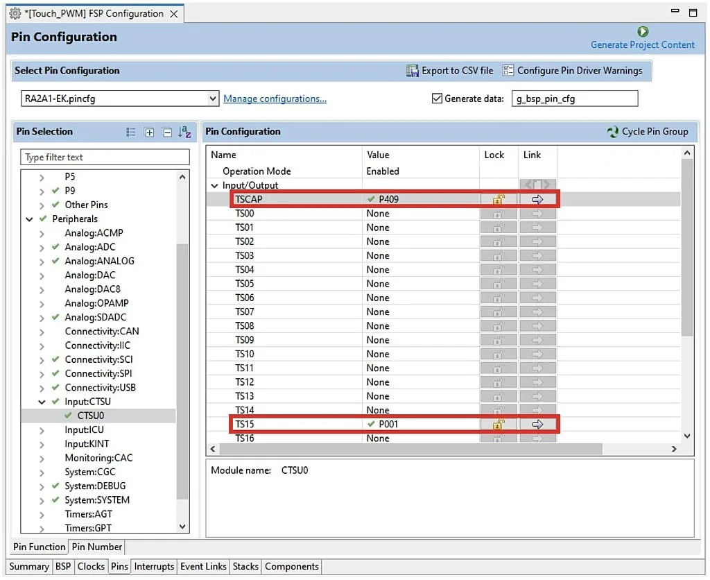
As usual, we first will work with the visual FSP configurator. First, we need to open the “Pins” tab, scroll down to the “Peripherals” list, expand the “Input: CTSU” item and select the “CTSU0” point. CTSU here stands for “Capacitive touch sensing unit”. Actually you don’t need to do anything here, just make sure that the pin P409 is configured as TSCAP, and pin P001 is configured as TS15 (Figure 1).
Here some clarification is needed, I guess. The CTSU module, as follows from its name, uses the capacitive method to detect touching. In simple words, the touch pad is a conductive pad. As you know from your physics course in school, if there are two conductive pads, there is a capacitance between them. The roles of the second conductive pad play the surrounding routes, the copper pours, other metal parts and elements. This improvised capacitor is used in an RC-generator circuit which is located inside the MCU. When you don’t touch the pad, the capacitance has a certain value, and the generated frequency also has some default value. If you bring your finger close to the tab, its capacitance increases because the finger is also a conductor. In this case the generated frequency decreases. If the decreasing frequency reaches a given minimum threshold, we consider that the touchpad has been touched.
The CTSU can work via two main methods: self-capacitance measuring and mutual-capacitance measuring. In the first method, the capacitance is measured between a single pad and the environment like I described before. In the second method, we measure the mutual-capacitance between the two pads. Such an approach allows creating something like matrix keypads and thus increases the number of touch buttons.
In the “CTSU0” configurator (Figure 1) you may see that there is some TSCAP pin, and 26 pins called TS00-TS25. TSCAP is the lowpass filter connection pin. A 0.01uF capacitor is connected to it in the board EK-RA2A1.
The TS00-TS25 pins are touchpad inputs. In the self-capacitance mode there can be up to 26 pads, and in the mutual-capacitance mode the number of pads increases to 26 x 26 / 2 = 338.
Now, as we make sure that the pins are configured correctly, we can switch to the “Stacks” pad and add the “Touch (rm_touch)” stack from the “CapTouch” drop-down list (Figure 2).

As you see, it has the prefix “rm_” which means that it belongs to the middleware interface. After adding this module, several connected blocks will appear (Figure 3).
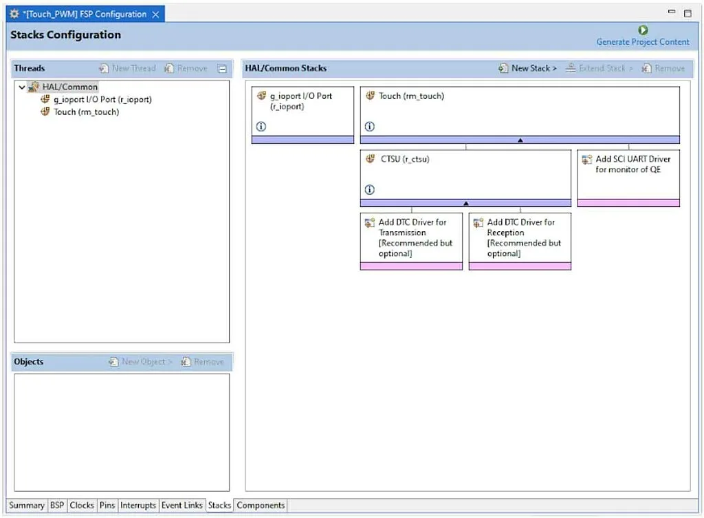
At the top level there is the middleware “Touch (rm_touch)” module. It has two submodules: “CTSU (r_ctsu)” which is the HAL (hardware abstraction level) driver of the CTSU module of the MCU, and “SCI UART Driver for monitor of QE” which is an optional UART driver to configure and monitor the Touch module parameters and values. In our current application we will not use it, so we’ll leave this block untouched. “CTSU (r_ctsu)” module in its turn has its own optional submodules: DTC driver for transmission and DTC driver for reception. DTC stands for “Data Transfer Controller”. This module performs the data transfer when activated by the interrupt request without CPU involvement. We will later add these modules to our project, as they are configured automatically, so they won’t cost us anything.
Now, let’s consider the properties of every module. The “Touch” block has the following parameters (Figure 4).
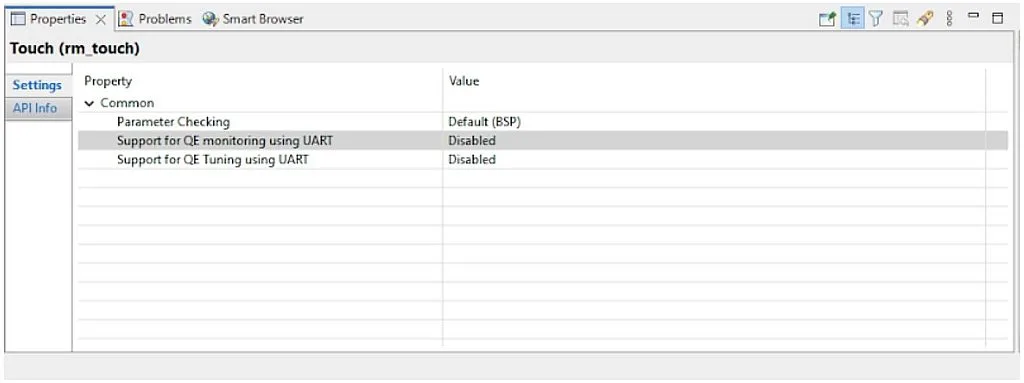
As you can see, there are only a few of them.
- “Parameter Checking” was considered in detail in the previous tutorial. It allows checking the functions arguments when it’s possible.
- “Support for QE monitoring using UART” allows the use of the UART interface to monitor the values of the Touch module.
- “Support for QE Tuning using UART” allows the use of the UART interface to adjust the parameters of the Touch module.
As I mentioned before, we’re not going to use the UART interface in the current program, so we leave all the parameters by default as shown in Figure 4.
Now, let’s click on the “CTSU” block and configure it (Figure 5).
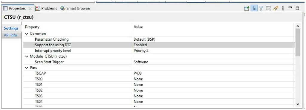
As you can see, the number of parameters has increased significantly:
- “Parameter Checking” is the same as in all other modules, so I’ll skip it when considering the further blocks.
- “Support for using DTC” - allows the use of the DTC module to transmit data from and to the CTSU module. As I mentioned before, it’s a good idea to use it to ease the load on the CPU whenever it’s possible. So we change this parameter to “Enabled”. Please note that after that, an error will appear in the CTSU block (Figure 6).
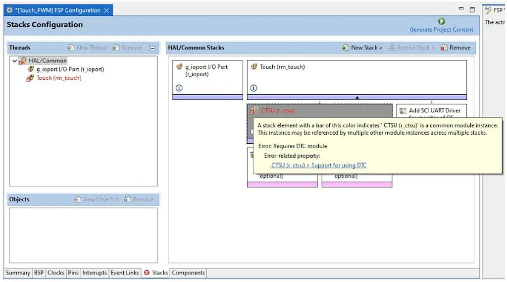
When you leave the mouse cursor over the block, you will see the hint about the reason for the error. In our case it occurred because we enabled using the DTC but didn’t add the DTC drivers. We will fix this issue later after considering all the parameters of the CTSU module.
- “Interrupt priority level” sets the priority level of the CSTU data read and settings write interrupts. We will not consider them in detail here. For more information please refer to the RA2A1 family (or whatever family you use) User Manual.
- “Scan Start Trigger” selects the signal that starts the scanning of the touch sensors. It can be either a software trigger or one of the external events (Port 1 event or Port 2 event). Here we will use software triggering, so nothing to be changed here.
- “TCAP” selects the pin to which the lowpass filter capacitor is connected. As we already have considered (see Figure 1) it should be the P409 pin.
- “TS00” - “TS25” select the pins to which the touch pads are connected. In our case, we just need to make sure that the P001 pin is connected to the “TS15”.
As you see, still not that much work for us here. Next, we need to add the transmission and reception DTC drivers to get rid of the errors. This is very simple: click on the “Add DTC Driver for Transmission”, you will see the pop-up menu “New >”. Open it and select the “Transfer (r_dtc)” module (Figure 7).
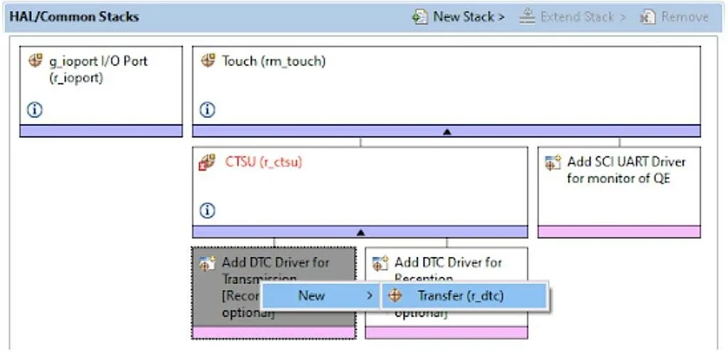
Then do the same for the “Add DTC driver for Reception” block. After that you will have the following Stacks view (Figure 8).
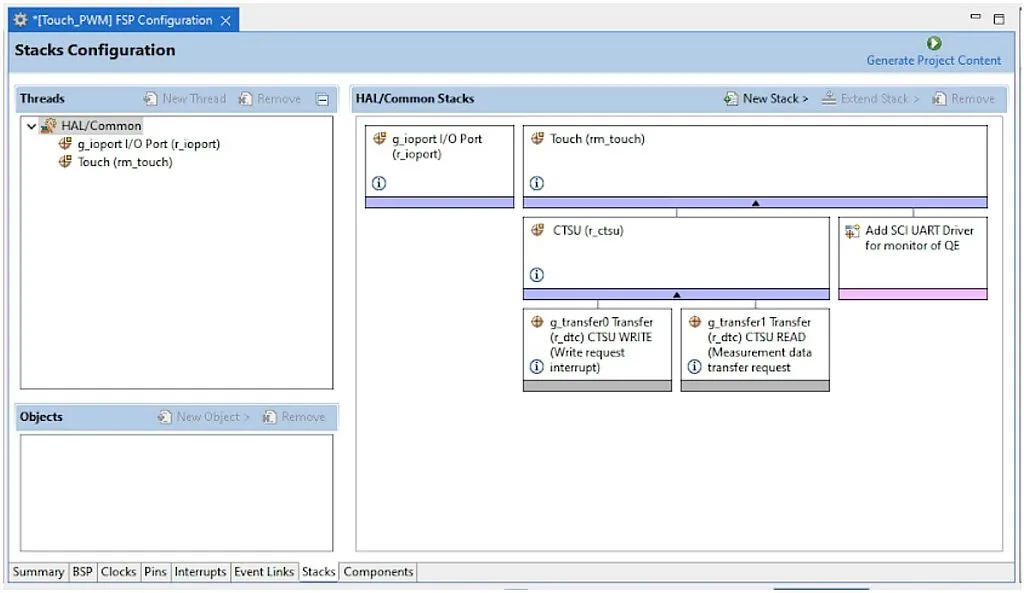
Please notice that the error has gone. You can look at the DTC modules properties but just out of curiosity. I will not consider them here now, as they are already configured and the majority of them are locked, so you shouldn’t (and, in most cases, can’t) change anything there.
Now to proceed with the setup of the touch interface we need to press the “Generate Project Content” button at the top right corner of the “FPS Configuration” window. There is a special third party QE module that configures the Capacitive Touch module. To open it, click on the “Renesas Views” in the main menu, open the “Renesas QE” list and select the “CapTouch Main QE” (Figure 9).

You will see the following window (Figure 10).
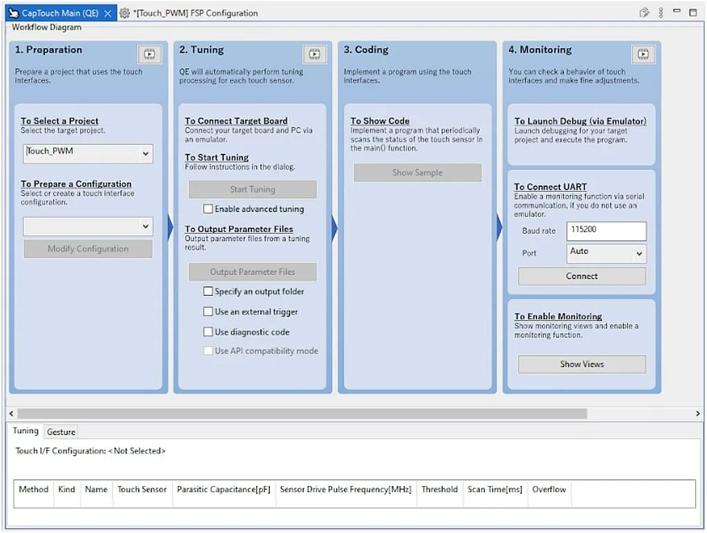
In this window you can, in a few simple steps, configure even a complex touch sensing interface including buttons, sliders, wheels etc. Let’s see how it’s done. In the “1. Preparation” column select the project where you want to add the touch interface. I called this project “Touch_PWM”, so I selected it in the drop-down list.
Next, in the “To Prepare a Configuration” drop-down list select the single available line “Create a new configuration”. You will see the next window (Figure 11).
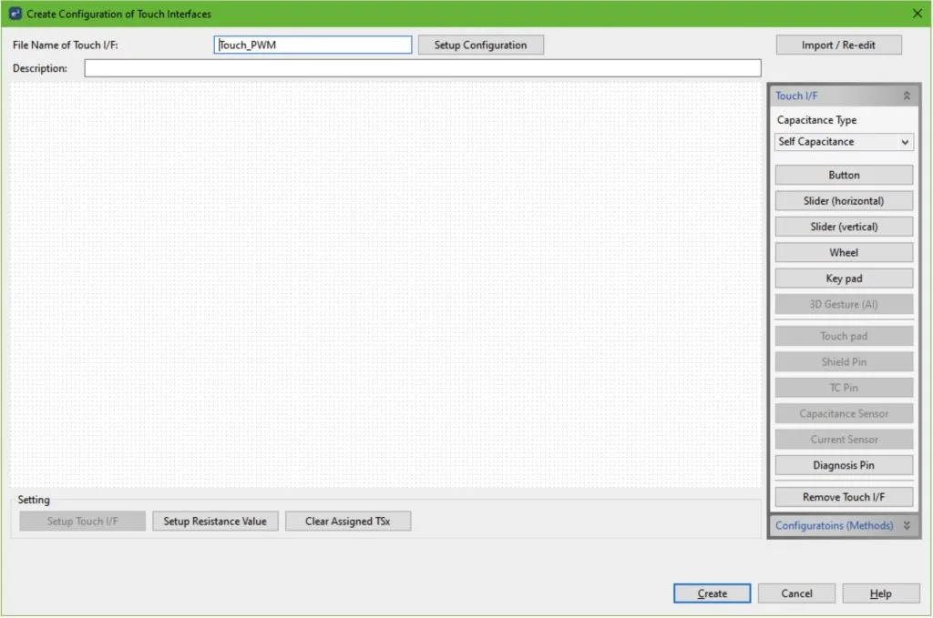
As you see there are plenty of options to add but we will do the simplest thing and select the “Button” in the right list. Then we place it in any place of the field. By default, the button name is Button00 (Figure 12).
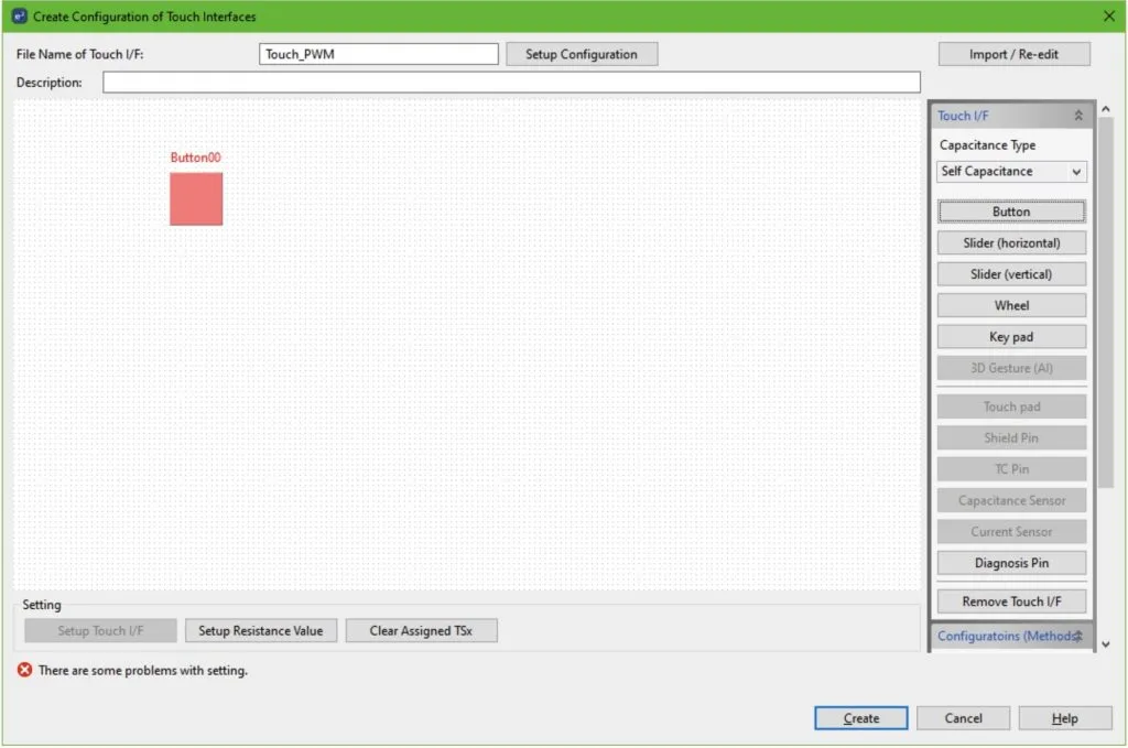
It shows the error “There are some problems with settings”. It appears because the button is not configured yet. To do this, double click on the Button00 square and configure it according to Figure 13.

As you should remember from Figure 1, our button is connected to the TS15 sensor, so we should select it. As for the resistance value, it can be found in the EK-RA2A1 board User Manual (Figure 14).

As follows from Figure 14, the series resistor R4 is 560 Ohm which is the value we put into the configuration window (Figure 13). After that we can press “OK”. As you see, now the error is gone, and the button square changed the color from red to green.
Now you can click on the “Create” button to finish the configuration creation process.
Next, we need to perform tuning of our button. This includes calculation of the button parameters in the normal state, and when you touch it. As follows from the “2. Tuning” column (Figure 10) you first need to connect your board to the PC via the debugger interface. Then build the project and make sure there are no errors in it.
Then click the button “Start Tuning”. The debug session will start automatically but this time it will not be a usual debug. You will see the following window instead (Figure 15).

As follows from Figure 15 there are six steps in this process. The first four of them will pass automatically and very fast. On the fifth step your action will be needed (Figure 16).

In this step you will need to touch the touch button. You will notice that the yellow bar becomes more filled, and the number at “Button00, TS15 @ config01:” becomes bigger (Figure 17). Now you can press any key on the PC keyboard to finish the tuning process.

You will see the next window (Figure 18).
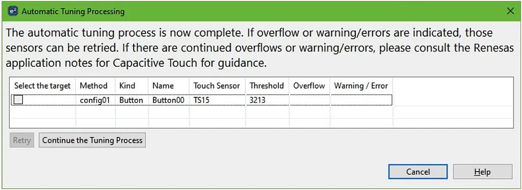
As you see, the tuning algorithm has calculated the sensitivity threshold. Now you can click on the button “Continue the Tuning Process” to close this window.
The next step is to click the “Output Parameter Files” in the “CapTouch Main QE” window. You can leave all the checkboxes unchecked. When you do this, you will notice in the project explorer that the new folder “qe_gen” has appeared in your project (Figure 19).

As you see, there are three files: “qe_touch_config.c”, “qe_touch_config.h” and “qe_touch_define.h”. They contain the needed tuning information to enable touch detection using the module of FSP. We will not consider them in detail, as we don’t need to dive deep into the things that the developers tried to simplify for us.
Now, let’s move to the column “3. Coding”. There is only one button “Show sample” which we can click. Then we will see the following window with the sample code (Figure 20).

We can click on the button “Output to a File” and make sure that in the “qe_gen” folder the new file “qe_touch_sample.c” appears. Now we can click on the “OK” button to close this window. We will consider this file in detail later, as in the current application we will write our code in it.
That’s actually all about the touch interface configuration. There is the last column in the “CapTouch Main QE” window called “4. Monitoring” but, for me, it’s not necessary in our simple application. If you want to know more about it, you can always refer to the RA Family Using QE and FSP to Develop Capacitive Touch Application application note mentioned before.
Now, let’s configure the PWM module. To do this, let’s return to the “FSP Configuration” perspective. Then in the “FSP Visualization” window right click on the P205 pin, to which the LED1 is connected. In the pop-up menu select the “GTIOCB” line (Figure 21).

Here GTIOCB stands for “General Timer Input Output Compare B”. There is also GTIOCA timer output but it’s merged with some other IO pin. Next, let’s open the “Pin” tab of the “FSP Configuration” window and find pin P205. Make sure that its function is “GPT3_GTIOCB” (Figure 22). The other parameters may remain the same.
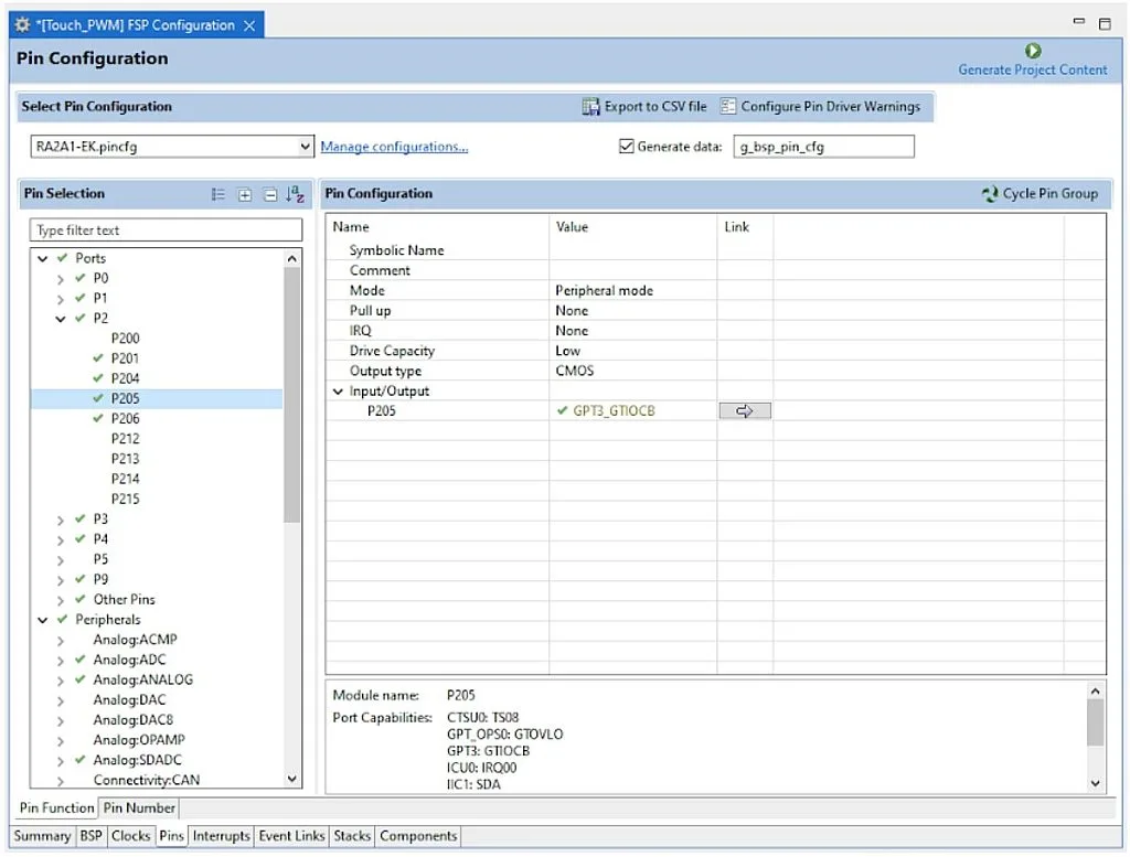
Let’s click on the arrow at the “Link” column to move to the peripherals-sorted view (Figure 23).
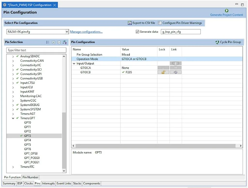
As you see, we have moved to the “Timers:GPT” section. “GPT” stands for “General Purpose Timer”. As you can see from Figure 23 it has seven channels, namely, GPT0-GPT7. They all are the same except for the GPT0 which is 32-bits, unlike the others which have 16-bit resolution. The features of the GPT timer are (taken from the RA2A1 User Manual):
- Up-counting, down-counting, and up-down-counting modes.
- Clock sources can be selected individually for each channel.
- Two I/O pins per channel, which are GTIOCA and GTIOCB, as I mentioned before.
- Two capture/compare registers per channel.
- Register for setting up frame cycles in each channel with capability for generating interrupts at overflow or underflow.
- Generation of dead times in PWM operation.
- Synchronous starting, stopping and clearing counters for arbitrary channels.
- Output pin disable function by detected short-circuits between output pins.
- PWM waveform for controlling brushless DC motors can be generated.
There are also other functions which we will consider when the time comes. Well, actually we won’t use the majority of the mentioned functions in this tutorial either but at least we can now understand what they mean.
To use the GPT timer in our application to control the brightness of the LED, we need to add the corresponding stack. So let’s switch to the “Stacks” tab, click on the “New Stack >” button, find the “Timers” line, and select the “Timer, General PWM (r_gpt)” item (Figure 24).

Now, let’s click on the just created block “g_timer0 Timer, General PWM (r_gpt)” and adjust its properties according to Figure 25.
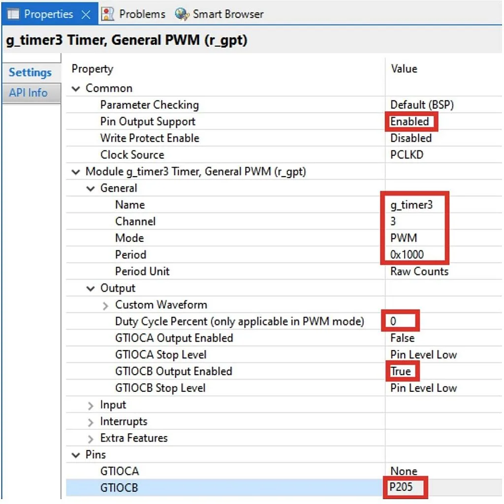
As you see, there are plenty of options, and some drop-down lists, namely “Input”, “Interrupt”, and “Extra Features” are not even expanded, as we will not use them now. Let’s consider the rest of the options. The ones that need to be changed are highlighted with the red frames.
- “Pin Output Support” allows the timer to control an output pin. As we need it to control the GTIOCB (P205) pin, we need to change this option to “Enabled”.
- “Write Protect Enable” allows you to prohibit writing to all GPT channels. As we will change the LED brightness (which means we need to change the PWM duty cycle), we keep this option disabled.
- “Clock Source” selects the source of the GPT clocking. The only available option is PCLKD, so we leave it unchanged.
- “Name” is the name of the module by which we will distinguish it in our program. As I mentioned before, the P205 pin is connected to the GPT3 channel, so let’s change the name from “g_timer0” to “g_timer3”.
- “Channel” selects the GPT channel. As I just said, we need the third channel, so let’s change this value from 0 to 3.
- “Mode” selects the operating mode of the current GPT channel. As you can see in the drop-down list there are plenty of them (Figure 26).

- “Periodic” generates interrupts with the selected period.
- “One-Shot” generates a single interrupt when the period expires, then stops.
- “PWM” generates a simple PWM on the selected output pin(s).
- “One-Shot Pulse” generates a single pulse on the selected output pin(s) then stops.
- All “Triangle-Wave PWM” options generate a PWM in the up-down counting mode. We will consider the differences between them when we consider controlling motors using this MCU.
- “Period” sets the timer period. Let’s change it to 0x1000, which is in hexadecimal.
- “Period Units” sets the measurement units of the timer period. Actually, this is a very convenient option, as you can select “Raw Counts”, “Nanoseconds”, “Microseconds”, “Milliseconds”, “Seconds”, “Hertz”, and “Kilohertz” here. We select the first option not to recalculate the PWM duty cycle value. So we set the period of 0x1000, or 65536 counts of the PCLKD source. In the “Clocks” tab you can see that it is 48 MHz, so the timer frequency is 48 / 65536 = 732 Hz, and the timer period is 1000000 / 732 = 1365 us.
- “Custom Waveform” list consists of the options that allow us to generate complex waveforms which we don’t need for now, so let’s just skip it (and don’t even expand).
- “Duty Cycle Percent” speaks for itself. As we want the LED1 to be turned off initially, let’s change its value from 50 to 0.
- “GTIOCA Output Enable” and “GTIOCB Output Enable” enable the corresponding output pin. As we use only the GTIOCB pin, we change only that one to “Enabled”.
- “GTIOCA Stop Level” and “GTIOCB Stop Level” set the output pin level when the timer is disabled. We leave the default value “Pin Level Low” in both cases.
- In the “Pins” list there are two lines “GTIOCA” which should remain empty, and “GTIOCB” which after making all the mentioned changes should automatically change to “P205”.
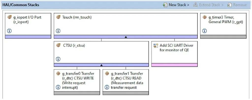
Now, our initial configuration on the MCU using the “FSP Configurator” is done, so let’s check that the “Stacks” tab looks exactly like in Figure 27, and then click on the “Generate Project Content” button once again, make sure that there are no errors, and open the “hal_entry.c” file.
In the “hal_entry.c” file we should write the next code.
#include "hal_data.h"


FSP_CPP_HEADER
void R_BSP_WarmStart(bsp_warm_start_event_t event);
FSP_CPP_FOOTER


void qe_touch_main(void); //Declaration of the qe_touch_main function located in "qe_touch_sample.c" file


/*******************************************************************************************************************//**
 * main() is generated by the RA Configuration editor and is used to generate threads if an RTOS is used.  This function
 * is called by main() when no RTOS is used.
 **********************************************************************************************************************/
void hal_entry(void)
{
	/* TODO: add your own code here */
	R_GPT_Open(&g_timer3_ctrl, &g_timer3_cfg);  //Configure GPT3
	R_GPT_Start(&g_timer3_ctrl);            	//Start GPT3
	qe_touch_main();                       //Switch to the "qe_touch_sample.c" file


#if BSP_TZ_SECURE_BUILD
	/* Enter non-secure code */
	R_BSP_NonSecureEnter();
#endif
}


/*******************************************************************************************************************//**
 * This function is called at various points during the startup process.  This implementation uses the event that is
 * called right before main() to set up the pins.
 *
 * @param[in]  event	Where at in the start up process the code is currently at
 **********************************************************************************************************************/
void R_BSP_WarmStart(bsp_warm_start_event_t event)
{
	if (BSP_WARM_START_RESET == event)
	{
#if BSP_FEATURE_FLASH_LP_VERSION != 0


/* Enable reading from data flash. */
    	R_FACI_LP->DFLCTL = 1U;


/* Would normally have to wait tDSTOP(6us) for data flash recovery. Placing the enable here, before clock and
     	* C runtime initialization, should negate the need for a delay since the initialization will typically take more than 6us. */
#endif
	}


if (BSP_WARM_START_POST_C == event)
	{
    	/* C runtime environment and system clocks are setup. */


/* Configure pins. */
    	R_IOPORT_Open (&g_ioport_ctrl, g_ioport.p_cfg);
	}
}


#if BSP_TZ_SECURE_BUILD


BSP_CMSE_NONSECURE_ENTRY void template_nonsecure_callable ();


/* Trustzone Secure Projects require at least one nonsecure callable function in order to build (Remove this if it is not required to build). */
BSP_CMSE_NONSECURE_ENTRY void template_nonsecure_callable ()
{


}
#endif
The same as in previous tutorials, I’ve highlighted the lines that I’ve added manually with the green color. As you can see there are just four of them, as the main part of the program will be located in the “qe_touch_sample.c” file.
So in line 7 we declare the qe_touch_main function which is located in the “qe_touch_sample.c” file. Actually, we don’t have to add this line, but in this case the compiler would give a warning about the “missing function declaration” and nothing else.
In line 16 we write the GPT timer configuration, and in line 17 we start it. The same as in the previous tutorial, I found the required code in the FSP documentation opened by clicking on the sign of the “g_timer3 Timer” block in the “Stacks” tab.
In line 18 we invoke the qe_touch_main function, and thus pass the code implementation to the “qe_touch_sample.c” file whose content is listed below.
/***********************************************************************
*
* FILE : qe_sample_main.c
* DATE : 2022-02-14
* DESCRIPTION : Main Program for RA
*
* NOTE:THIS IS A TYPICAL EXAMPLE.
*
***********************************************************************/
#include "qe_touch_config.h"
#define TOUCH_SCAN_INTERVAL_EXAMPLE (20)	/* milliseconds */


void qe_touch_main(void);


uint64_t button_status;
#if (TOUCH_CFG_NUM_SLIDERS != 0)
uint16_t slider_position[TOUCH_CFG_NUM_SLIDERS];
#endif
#if (TOUCH_CFG_NUM_WHEELS != 0)
uint16_t wheel_position[TOUCH_CFG_NUM_WHEELS];
#endif


uint16_t duty;
uint8_t previous_status;
uint32_t tick;


void qe_touch_main(void)
{
    fsp_err_t err;


/* Open Touch middleware */
    err = RM_TOUCH_Open(g_qe_touch_instance_config01.p_ctrl, g_qe_touch_instance_config01.p_cfg);
    if (FSP_SUCCESS != err)
    {
    	while (true) {}
    }


/* Main loop */
    while (true)
    {
    	/* for [CONFIG01] configuration */
    	err = RM_TOUCH_ScanStart(g_qe_touch_instance_config01.p_ctrl);
    	if (FSP_SUCCESS != err)
    	{
        	    while (true) {}
    	}
    	while (0 == g_qe_touch_flag) {}
    	g_qe_touch_flag = 0;


err = RM_TOUCH_DataGet(g_qe_touch_instance_config01.p_ctrl, &button_status, NULL, NULL);
    	if (FSP_SUCCESS == err)
    	{
        	    if ((button_status == 1) && (previous_status == 0))   //If the current button state is low and previous state is high
        	    {
            	previous_status = 1;  //We reset the previous state to 0 to prevent implementation of this branch the next time
        	    }
        	    else if ((button_status == 0) && (previous_status == 1))   //If the current button state is high and previous state is low
        	    {
            	previous_status = 0; //Then we set the previous state as 1 to prevent implementation of this branch the next time
        	    }
        	    else if ((button_status == 1) && (previous_status == 1)) //If both states are high (button is held touched)
        	    {
            	if (tick % 25 == 0) //This condition becomes true every 500 ms
            	{
                	    if (duty < 0x1000)  //If PWM duty cycle is less than the timer period
                    	        duty += 0x100;  //Then increment the duty cycle
                	    else            	//If we exceed the timer period
                    	        duty = 0;   	//Then reset the duty cycle to 0
                	    R_GPT_DutyCycleSet(&g_timer3_ctrl, duty, BSP_IO_PORT_02_PIN_05);//Write the duty cycle to the PWM register
            	}
        	    }
    	}


/* FIXME: Since this is a temporary process, so re-create a waiting process yourself. */
    	R_BSP_SoftwareDelay(TOUCH_SCAN_INTERVAL_EXAMPLE, BSP_DELAY_UNITS_MILLISECONDS);
    	tick ++; //Increment the tick variable
	}
}
As you see, in this file there are more green lines which we added manually. But let’s consider all of them to understand how the application works in general.
In line 10 we include the “qe_touch_config.h” file which consists of the declarations of the variables and functions required for operation of the touch interface.
In line 11 we set the interval between scans of the touch button state. I left this value by default as 20 ms.
In line 13 there is again declaration of the qe_touch_main function which is located in lines 27-78.
In line 15 we declare the variable button_status which has the uint64_t type to be able to consist of states of up to 64 touch buttons, but in our case it takes only two values: 0 if the button is not touched, and 1 otherwise.
Lines 16-21 are grayed which means that they are not active. They are used to process the touch sliders (lines 16-18) and wheels (lines 19-21).
In lines 23-25 we declare some own variables:
- duty (line 23) which represents the duty cycle of the PWM in the range 0x0000 - 0xF000.
- previous_status (line 24) which is the touch button status at the previous reading.
- tick (line 25) which is the counter of 20 ms intervals, needed for touch button processing.
In lines 27-78, as I mentioned before, there is the qe_touch_main function which in this case plays the role of the main function of the program.
In line 29 the err variable of the fsp_err_t type is declared. This variable is used to check the result of implementation of the FSP functions.
In line 32 we invoke the function RM_TOUCH_Open, in which we apply the configuration of the touch interface (g_qe_touch_instance_config01.p_cfg) to the control variable g_qe_touch_instance_config01.p_ctrl.
Even though this function was generated automatically by the QE CapTouch, you still can find the proper sequence of the operation with the touch module in the FSP documentation by clicking the sign of the “Touch (rm_touch)” block in the “Stacks” tab.
In line 33 we check if the result of the function is FSP_SUCCESS (which apparently means that the operation was successful) If it’s not so, we hang the program for good in line 35 where the while (true) loop is implemented.
Otherwise we proceed to the main loop of the program, located in lines 39-77.
In this loop we first start scanning the touch button state by calling the RM_TOUCH_ScanStart function (line 42). If the result of the function is not FSP_SUCCESS (line 43), we hang our program here (line 45).
In line 47 we check while the g_qe_touch_flag variable is 0. To better understand the meaning of this line, we need to open the “qe_touch_config.c” file and find there the qe_touch_callback function which is invoked by the interrupt subroutine when the touch button scanning is done. The content of this callback is the following:
void qe_touch_callback(touch_callback_args_t * p_args)
{
	g_qe_touch_flag = 1;
	g_qe_ctsu_event = p_args -> event;
}
As you see, in this function we first assign 1 to the g_qe_touch_flag variable, and then save the event that caused the interrupt in the g_qe_ctsu_event (actually we don’t need it for now, so we will just ignore it).
So let’s now return to the main loop of the program. In line 47 we wait until the g_qe_touch_flag variable becomes 1. This happens when the scan finished interrupt occurs. After that we can move forward to line 48, in which we reset this variable to 0 to prepare it for the next scanning.
In line 50 we invoke the function RM_TOUCH_DataGet which gets the result of scanning and saves it into the button_status variable. As I mentioned before, in our case it takes two values: 1 if the button is touched, and 0 if not.
In line 51 we check if the result of the function is FSP_SUCCESS. If it is, we proceed to the processing of the button. Here we will use the non-blocking algorithm of the button processing which I described in detail in this tutorial: Embedded C Programming with the PIC18F14K50 - 8. Non-blocking operations with Buttons and LEDs.
But here it will be simplified as the scanning period is just 20 ms, so we don’t need to perform the button debounce removal.
In line 53 we check if the current button state (button_status) is 1, and previous button state (previous_status) is 0. This happens in the moment when we just touched the button. Actually we don’t need to do anything in this case, so we just assign 1 to the previous_status so in the next iteration we will not get into this branch (line 55).
Lines 57-60 are opposite to lines 53-56. Here we catch the moment when we just have released the button, and thus assign 0 to the previous_status.
In line 61 we check if both button_status and previous_status are 1 which is true all the time while the button is touched. In this case we check if the modulo of division of the tick variable by 25 is 0 (which happens once in 500 ms) (line 63). If this condition is true we increment the duty variable by 0x100 (line 66) if it’s less than 0x1000 (line 65) to increase the LED brightness. Otherwise (line 67) we reset it to 0 (line 68) to turn the LED off. In line 69 we write the duty value to the GPT3 PWM compare register by invoking the R_GPT_DutyCycleSet function. I found its syntax using the Developer Assistance, which I talked about in the previous tutorial.
That’s all about the touch button processing. Next, in line 75 we implement a 20 ms delay by invoking the familiar function of R_BSP_SoftwareDelay. The comment in line 74 says that this is not the best solution but it’s fine for us as we don’t make anything else in our program.
Finally in line 76 we increment the tick variable.
And that’s all about the program code. Now you can connect your board to the PC, make the project to make sure there are no errors in it, start the debug session, and run the program. If you have done everything correctly, you should see that when you touch the sensor, the brightness of the LED increases every 500 ms. When it reaches the max value (in 16 steps), it resets to 0, and the process repeats. When you release the sensor, the brightness remains on the last level.
As you see, even such a complex thing as a touch sensor can be processed quite simply with the built-in e2 studio IDE QE CapTouch module.
As homework, I suggest you familiarize yourself with the QE CapTouch module and implement the Monitoring function (column 4 in Figure 10) of the touch button, as it’s described in the “Using QE and FSP to Develop Capacitive Touch Applications” application note (I’m not providing the link because it can be broken by the time you read this tutorial, so please find it by its title). I assure you, it will be fun!

Get the latest tools and tutorials, fresh from the toaster.


