Infrared RGB LED controller - Part 19 Microcontroller Basics (PIC10F200)
Published
Note: Microchip recently made some changes and their newer IDE versions use the XC8 compiler for Assembly, whereas all sample code here is created for the MPASM compiler. However, the sample code has been ported to XC8 by user tinyelect on our Discord channel (to whom we are extremely grateful!) and the XC8 version of the code is at the bottom of this tutorial for your reference. To see the changes needed to switch from MPASM to XC8, please check out the process that he shared.
Hi again! It’s time for a new tutorial! Today, I’ll tell you how to receive and process the signals from the IR remote. Basically, the task will consist of two parts. In the first part, we will receive the code of the button of the IR remote, decode it and display on the well-known 7-segment LED indicator. In the second part we will use the obtained information to control an RGB LED using the IR remote (set specific color/turn on/turn off).
As usual, let’s first consider how the IR controller works. Actually there are plenty of IR protocols which are very different: they use different coding schemes, different timings, different packet formats. We will consider one of the earliest and the most widespread protocols which was designed by NEC, and thus it’s called “NEC protocol”.
The packet consists of the preamble followed by 4 data bytes: address, inverted address, command, data command (see figure 1)

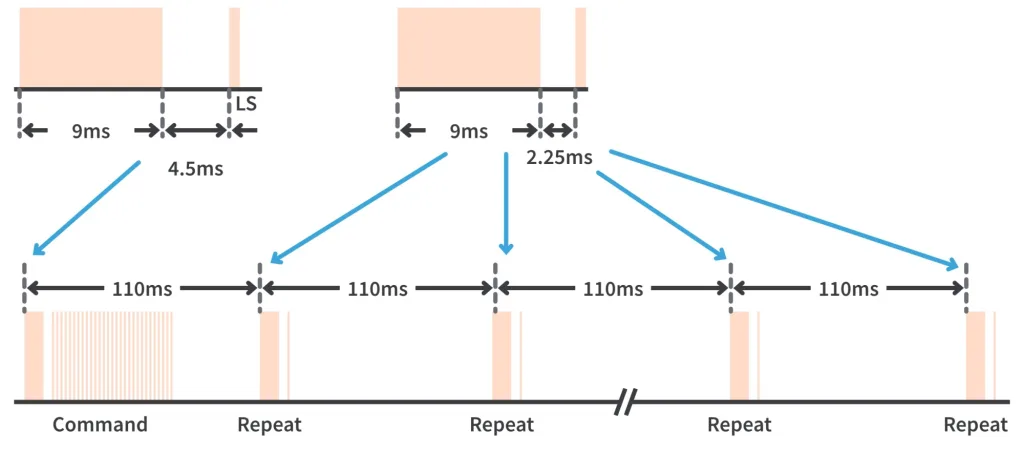
If you keep the button pressed for some time, only the first packet looks like the one shown in figure 1. The other packets are shorter and follow with the period of 110 ms (see figure 2).
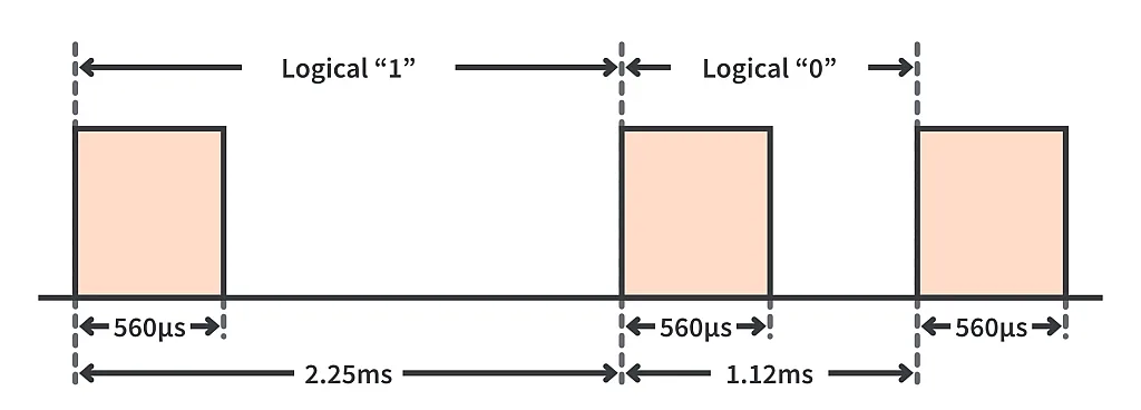
The bits are coded by the length of the pause (1.6ms for ‘1’ and 0.56ms for ‘0’) between pulses of the fixed length (0.56ms), see figure 3.
On a physical level, the IR signal represents the modulated infrared beam emitted by the IR diode. The carrying frequency for the NEC protocol is 38 kHz. So the remote modulates the pulses with this frequency and sends it off. The IR receiver consists of the demodulator which removes the carrying frequency and leaves just the initial pulses (figure 4).
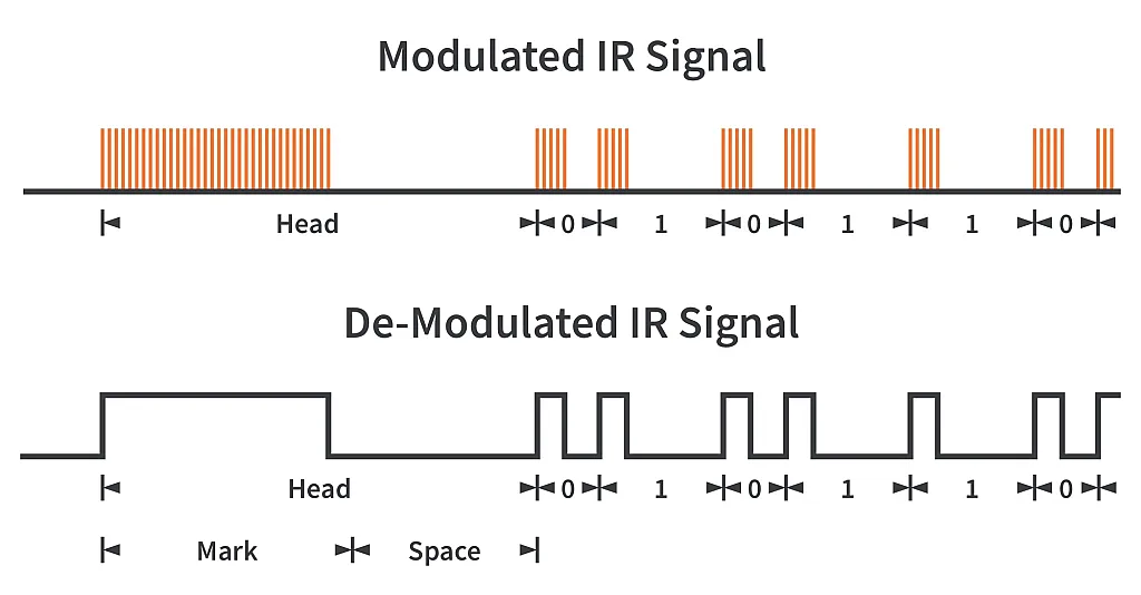
This modulation-demodulation stuff is used to increase the noise immunity of the IR channel, as there are a lot of the IR sources around us, and they all can cause false pulses.
As we are now familiar with the IR communication a bit, let’s consider the tools we will use in our program.
First, we need the IR remote. You can use the one from the Arduino set (figure 5). As for me, I used the special IR remote which came with an IR-controlled RGB LED strip (figure 6).
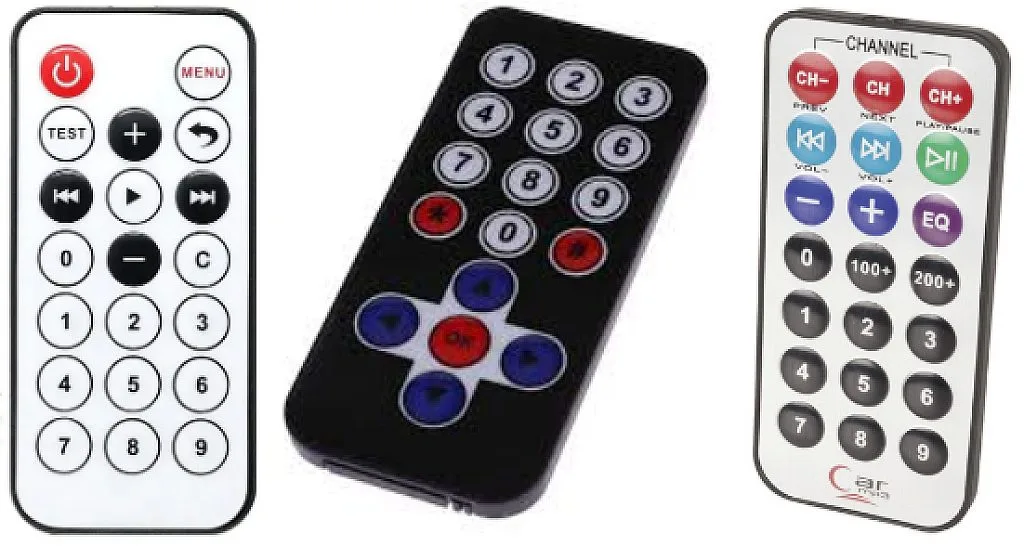

They all use the NEC protocol, and as long as you will know the codes of each button, you are free to use any remote you have or like.
Also, we will need the IR receiver. I recommend to use the TL1838 (VS1838) one (fig. 7), it’s very widespread, cheap, and easy to use. As you see in fig. 7, it has just 3 pins: VCC, GND, and SIGNAL. The supply voltage is 2.7 - 6.0 V. This receiver has the in-built IR decoder, which means that there are ready-to-use pulses at the SIGNAL pin, so all we need to do is to directly connect this pin to one of the GPIOs of the microcontroller and measure the duration of the pulses to decode the IR packet.

As for the RGB LED which we will control, I used the one from the Arduino set (see figure 8).
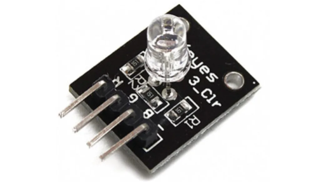
As you see, it has four pins: ‘R’, ‘B’, and ‘G’ represent the anodes of the red, blue, and green LEDs correspondingly; ‘-’ pin represents the common cathode of all three LEDs. Also you will notice that there are three current-limiting resistors on the module, so you can connect its pins directly to the microcontroller’s GPIOs.
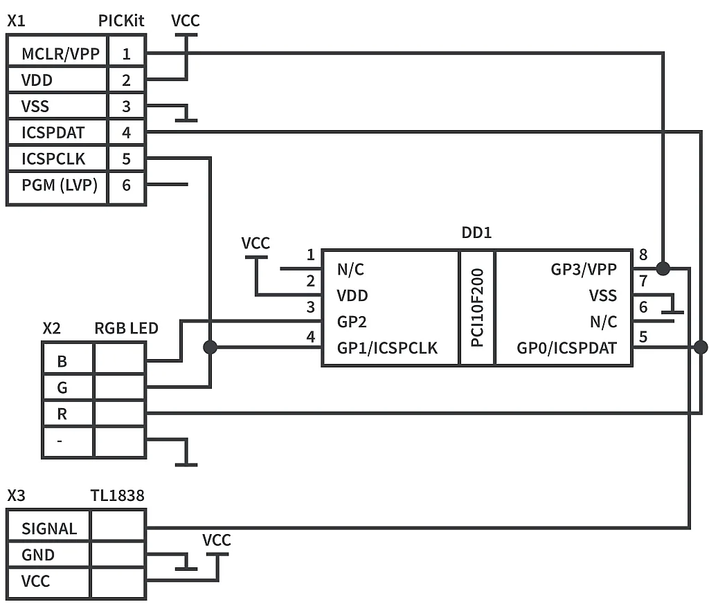
And now we’re good to consider the schematic diagram of the device. We will have two schematics this time: one for displaying the code of the button on the 7-segment display (Figure 9), and another for controlling the LED (Figure 10).
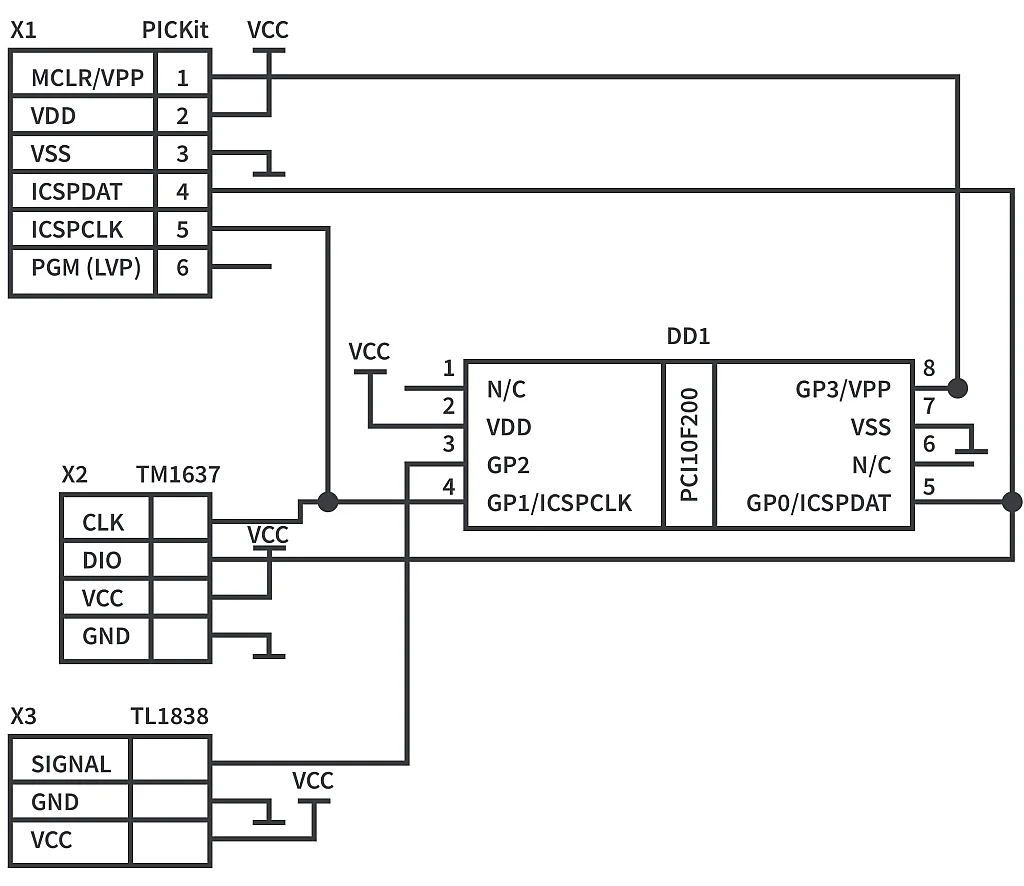
In figure 9, you see the inevitable microcontroller PIC10F200 (DD1) and the programmer (X1). Also there is the familiar 7-segment LED display TM1637 (X2) and the only new part is the IR receiver TL1838 (X3) which is connected to GP2 of the microcontroller.
In figure 10, there is the RGB LED module (X2) instead of the LED display. Its LEDs are connected to all three GPIOs of the microcontroller which can act as outputs: GP0, GP1, GP2. Thus we have to connect the IR receiver (X3) to the GP3 pin. Please be careful and don’t forget to disconnect the IR receiver during programming to avoid breaking it due to the high voltage.
Actually, the only reason why the IR receiver is connected to GP2 in figure 9 is that I was too lazy to plug and unplug the wire before and after each programming, and in figure 10 there is no choice: we have only one free pin.
OK, let’s finish with the hardware part and consider the firmware one.
#include "p10f200.inc"

#define DISPLAY      ;Display mode
#undefine DISPLAY    ;Uncomment for normal mode

count   	 EQU 10    ;Saved value of the timer
byte_count   EQU 11    ;Counter of processed bytes
bit_count    EQU 12    ;Counter of processed bits
tw_data   	 EQU 13    ;Data to receive/transmit via TWI
port   	     EQU 14    ;Helper register to implement 1-wire and TWI
ack   		 EQU 15    ;Acknowledgment received from the TWI device
digit   	 EQU 16    ;Digit to be decoded for the display
num_l   	 EQU 17    ;Lower nibble of the number
num_h   	 EQU 18    ;Higher nibble of the number
color   	 EQU 19    ;Stores the color of the RGB LED
ir_data   	 EQU 1A    ;First IR byte

#ifdef DISPLAY
dio   		 EQU    GP0    ;DIO pin of the display
clk   		 EQU    GP1    ;CLK pin of the display
ir   		 EQU    GP2    ;IR
#else
red   		 EQU    GP0    ;Red LED
green   	 EQU    GP1    ;Green LED
blue   	     EQU    GP2    ;Blue LED
ir   		 EQU    GP3    ;IR
#endif

    __CONFIG _WDT_OFF & _CP_OFF & _MCLRE_OFF

	ORG 0x0000

INIT
    MOVLW  ~((1<<T0CS)|(1<<PSA))  ;enable GPIO2
	 OPTION   			          ;and set timer prescaler to 256

#ifdef DISPLAY
    MOVLW (1<<dio)|(1<<clk)|(1<<ir)
    MOVWF port   		 ;It's used to switch DIO/CLK pins direction
    TRIS GPIO   		 ;Set 'clk', 'dio', and 'ir' as inputs
#else
    MOVLW (1<<ir)
    TRIS GPIO   		 ;Set 'ir' as input
    MOVLW (1 << green) | (1 << red) | (1 << blue)  ;Set the white color
    MOVWF color   		 ;for the 'color' register
#endif

    CLRF GPIO    		 ;Clear GPIO to set all pins to 0

LOOP   				     ;Main loop of the program
;---------------Wait for the preamble positive pulse---------------------
    BTFSC GPIO, ir   	 ;Wait while 'ir' pin goes down
    GOTO LOOP   		 ;If it's high then return to 'LOOP'
    CLRF TMR0   		 ;Otherwise clear the timer register
    BTFSS GPIO, ir   	 ;And wait while 'ir' is low
    GOTO $-1
    MOVF TMR0, W   	     ;Copy the TMR0 value into the W register
    MOVWF count   		 ;and save the value into the 'count' register
    MOVLW D'30'   		 ;Load 30 into W (256 us x 32 = 7.7 ms)
    SUBWF count, W   	 ;And subtract W from 'count'
    BTFSS STATUS, C   	 ;If 'count' < 30 (pulse is shorter than 7.7 ms)
    GOTO LOOP   		 ;then return to 'LOOP'
    MOVLW D'45'   		 ;Load 45 into W (256 us x 45 = 11.5 ms)
    SUBWF count, W   	 ;And subtract W from 'count'
    BTFSC STATUS, C   	 ;If 'count' > 45 (pulse is longer than 8 ms)
    GOTO LOOP   		 ;then return to 'LOOP'
;---------------Check the preamble negative pulse---------------------
    CLRF TMR0   		 ;Otherwise clear the timer register
    BTFSC GPIO, ir   	 ;And wait while 'ir' is high
    GOTO $-1
    MOVF TMR0, W   	     ;Copy the TMR0 value into the W register
    MOVWF count   		 ;and save the value into the 'count' register
    MOVLW D'13'   		 ;Load 15 into W (256 us x 13 = 3.3 ms)
    SUBWF count, W   	 ;And subtract W from 'count'
    BTFSS STATUS, C   	 ;If 'count' < 13 (pulse is shorter than 3.3 ms)
    GOTO LOOP   		 ;then return to 'LOOP'
    MOVLW D'20'   		 ;Load 20 into W (256 us x 20 = 5.1 ms)
    SUBWF count, W   	 ;And subtract W from 'count'
    BTFSC STATUS, C   	 ;If 'count' > 20 (pulse is longer than 5.1 ms)
    GOTO LOOP   		 ;then return to 'LOOP'
;---------------Receive the command bytes-----------------------------
    CLRF byte_count   	 ;Clear the 'byte_count' register
    MOVLW ir_data   	 ;Load the address of the 'ir_data' into W
    MOVWF FSR   		 ;and save it to the indirect pointer register
RECEIVE_BYTE
    CLRF bit_count   	 ;Clear the 'bit_count' register
    CLRF INDF   		 ;Clear the indirectly addressed register
RECEIVE_BIT
    RRF INDF, F   		 ;Shift the INDF register to the right
;---------------Receive the positive pulse of the bit-----------------
    CLRF TMR0   		 ;Otherwise clear the timer register
    BTFSS GPIO, ir   	 ;And wait while 'ir' is low
    GOTO $-1
    MOVF TMR0, W   	     ;Copy the TMR0 value into the W register
    MOVWF count   		 ;and save the value into the 'count' register
    MOVLW D'1'   		 ;Load 1 into W (256 us x 1 = 0.26 ms)
    SUBWF count, W   	 ;And subtract W from 'count'
    BTFSS STATUS, C   	 ;If 'count' < 1 (pulse is shorter than 0.26 ms)
    GOTO LOOP   		 ;then return to 'LOOP'
    MOVLW D'3'   		 ;Load 3 into W (256 us x 3 = 0.77 ms)
    SUBWF count, W   	 ;And subtract W from 'count'
    BTFSC STATUS, C   	 ;If 'count' > 3 (pulse is longer than 0.77 ms)
    GOTO LOOP   		 ;then return to 'LOOP'
;---------------Receive the negative pulse of the bit-----------------
    CLRF TMR0   		 ;Otherwise clear the timer register
    BTFSC GPIO, ir   	 ;And wait while 'ir' is high
    GOTO $-1
    MOVF TMR0, W   	     ;Copy the TMR0 value into the W register
    MOVWF count   		 ;and save the value into the 'count' register
    MOVLW D'4'   		 ;Load 5 into W (256 us x 4 = 1.1 ms)
    SUBWF count, W   	 ;And subtract W from 'count'
    BTFSS STATUS, C   	 ;If 'count' < 4 (pulse is shorter than 1.1 ms)
    GOTO NEXT_BIT   	 ;then go to the 'NEXT_BIT' label
    MOVLW D'8'   		 ;Load 8 into W (256 us x 8 = 2 ms)
    SUBWF count, W   	 ;And subtract W from 'count'
    BTFSC STATUS, C   	 ;If 'count' > 8 (pulse is longer than 2 ms)
    GOTO LOOP   		 ;then go to the 'LOOP' label
    BSF INDF, 7   		 ;Set the MSB of the INDF register
NEXT_BIT
    INCF bit_count, F    ;Increment the 'bit_count' register
    BTFSS bit_count, 3   ;Check if 'bit_count' becomes 8
    GOTO RECEIVE_BIT     ;If it's not, then return to 'RECEIVE_BIT' label
    INCF byte_count, F   ;Increment the 'byte_count' register
    BTFSC byte_count, 2  ;Check if 'byte_count' becomes 4
    GOTO CHECK_DATA   	 ;If it is then go to 'CHECK_DATA' label
    INCF FSR, F   		 ;Increment the indirect addressing pointer
    GOTO RECEIVE_BYTE    ;and go to 'RECEIVE_BYTE' label

CHECK_DATA
    COMF ir_data+1, W    ;Negate the second received byte
    XORWF ir_data, W     ;And implement the XOR between 1st and 2nd bytes
    BTFSS STATUS, Z   	 ;If the result is not 0 (bytes are not equal)
    GOTO LOOP   		 ;Then return to the 'LOOP' label
    COMF ir_data+3, W    ;Negate the fourth received byte
    XORWF ir_data+2, W   ;And implement the XOR between 3rd and 4th bytes
    BTFSS STATUS, Z   	 ;If the result is not 0 (bytes are not equal)
    GOTO LOOP   		 ;Then return to the 'LOOP' label

#ifdef DISPLAY
;Send first command to LED display
    CALL TW_START   	 ;Issue Start condition
    MOVLW 0x40   		 ;Send command 0x40 -
    CALL TW_WRITE_BYTE   ;"Write data to display register"
    CALL TW_STOP   	     ;Issue Stop condition
;Send second command and data to LED display
    CALL TW_START   	 ;Issue Start condition
    MOVLW 0xC0   		 ;Send address 0xC0 -
	 CALL TW_WRITE_BYTE  ;The first address of the display
    MOVF ir_data, W
    CALL SPLIT_NUM
    MOVF num_h, W
    CALL DECODE_DIGIT    ;Get the display data
	 CALL TW_WRITE_BYTE  ;Write the first digit to the display
    MOVF num_l, W
    CALL DECODE_DIGIT    ;Get the display data
	 CALL TW_WRITE_BYTE  ;Write the second digit to the display
    MOVF ir_data + 2, W
    CALL SPLIT_NUM
    MOVF num_h, W
    CALL DECODE_DIGIT    ;Get the display data
    CALL TW_WRITE_BYTE   ;Write the second digit to the display
    MOVF num_l, W
    CALL DECODE_DIGIT    ;Get the display data
	 CALL TW_WRITE_BYTE  ;Write the fourth digit to the display
    CALL TW_STOP   	     ;Issue Stop condition
;Send brightness command to LED display
    CALL TW_START   	 ;Issue Start condition
    MOVLW 0x8F   		 ;Send display control byte 0x8F -
    CALL TW_WRITE_BYTE   ;"Display ON"
    CALL TW_STOP    	 ;Issue Stop condition
#else
    MOVLW 0x09   		 ;Check the R button (code 0x09)
    XORWF ir_data+2, W   ;If command is not 0x09
    BTFSS STATUS, Z
    GOTO $+4   		     ;then skip the next three lines
    MOVLW (1 << red)     ;Otherwise set the 'red' bit
    MOVWF color   		 ;of the 'color' register
    GOTO SET_OUTPUT   	 ;and go to the 'SET_OUTPUT' label

    MOVLW 0x08   		 ;Check the G button (code 0x08)
    XORWF ir_data+2, W   ;If command is not 0x08
    BTFSS STATUS, Z
    GOTO $+4   		     ;then skip the next three lines
    MOVLW (1 << green)   ;Otherwise set the 'green' bit
    MOVWF color   		 ;of the 'color' register
    GOTO SET_OUTPUT   	 ;and go to the 'SET_OUTPUT' label

    MOVLW 0x0A   		 ;Check the B button (code 0x0A)
    XORWF ir_data+2, W    ;If command is not 0x0A
    BTFSS STATUS, Z
    GOTO $+4   		 ;then skip the next three lines
    MOVLW (1 << blue)    ;Otherwise set the 'blue' bit
    MOVWF color   		 ;of the 'color' register
    GOTO SET_OUTPUT   	 ;and go to the 'SET_OUTPUT' label

    MOVLW 0x0B   		 ;Check the W button (code 0x0B)
    XORWF ir_data+2, W    ;If command is not 0x0B
    BTFSS STATUS, Z
    GOTO $+4   		 ;then skip the next three lines
    MOVLW (1 << blue) | (1 << red) | (1 << green);Otherwise set all bits
    MOVWF color   		 ;of the 'color' register
    GOTO SET_OUTPUT   	 ;and go to the 'SET_OUTPUT' label

    MOVLW 0x11   		 ;Check the Yellow button (code 0x11)
    XORWF ir_data+2, W    ;If command is not 0x11
    BTFSS STATUS, Z
    GOTO $+4   		 ;then skip the next three lines
    MOVLW (1 << green) | (1 << red)    ;Otherwise set the 'green' and 'red' bits
    MOVWF color   		 ;of the 'color' register
    GOTO SET_OUTPUT   	 ;and go to the 'SET_OUTPUT' label

    MOVLW 0x14   		 ;Check the Cyan button (code 0x14)
    XORWF ir_data+2, W    ;If command is not 0x14
    BTFSS STATUS, Z
    GOTO $+4   		 ;then skip the next three lines
    MOVLW (1 << green) | (1 << blue);Otherwise set the 'green' and 'blue' bits
    MOVWF color   		 ;of the 'color' register
    GOTO SET_OUTPUT   	 ;and go to the 'SET_OUTPUT' label

    MOVLW 0x12   		 ;Check the Magenta button (code 0x12)
    XORWF ir_data+2, W   ;If command is not 0x12
    BTFSS STATUS, Z
    GOTO $+4   		     ;then skip the next three lines
    MOVLW (1 << blue) | (1 << red)    ;Otherwise set the 'blue' and 'red' bits
    MOVWF color   		 ;of the 'color' register
    GOTO SET_OUTPUT   	 ;and go to the 'SET_OUTPUT' label

    MOVLW 0x07   		 ;Check the ON button (code 0x07)
    XORWF ir_data+2, W   ;If command is not 0x07
    BTFSS STATUS, Z
    GOTO $+2   		     ;then skip the next line
    GOTO SET_OUTPUT   	 ;and go to the 'SET_OUTPUT' label

    MOVLW 0x06   		 ;Check the OFF button (code 0x07)
    XORWF ir_data+2, W   ;If command is not 0x07
    BTFSS STATUS, Z
    GOTO $+2   		     ;then skip the next line
    CLRF GPIO   		 ;Clear the GPIO register
    GOTO LOOP   		 ;and go to the 'SET_OUTPUT' label

SET_OUTPUT
    MOVF color, W   	 ;Copy the value of the 'color' register
    MOVWF GPIO   		 ;into the GPIO register
#endif

	GOTO LOOP       	;loop forever

#ifdef DISPLAY
;-------------Helper subroutines---------------
DIO_HIGH   			 ;Set DIO pin high
    BSF port, dio   	 ;Set 'dio' bit in the 'port' to make it input
    MOVF port, W   	 ;Copy 'port' into W register
	TRIS GPIO   		 ;And set it as TRISGPIO value
    RETLW 0

DIO_LOW   				 ;Set DIO pin low
    BCF port, dio   	 ;Reset 'dio' bit in the 'port' to make it output
    MOVF port, W   	 ;Copy 'port' into W register
	TRIS GPIO   		 ;And set it as TRISGPIO value
    RETLW 0

CLK_HIGH   			 ;Set CLK pin high
    BSF port, clk   	 ;Set 'clk' bit in the 'port' to make it input
    MOVF port, W   	 ;Copy 'port' into W register
	TRIS GPIO   		 ;And set it as TRISGPIO value
    RETLW 0

CLK_LOW   				 ;Set CLK pin low
    BCF port, clk   	 ;Reset 'clk' bit in the 'port' to make it output
    MOVF port, W   	 ;Copy 'port' into W register
	TRIS GPIO   		 ;And set it as TRISGPIO value
    RETLW 0
;-------------TW start condition--------------
TW_START
    CALL CLK_HIGH   	 ;Set CLK high
    CALL DIO_LOW   	 ;Then set DIO low
    RETLW 0
;-------------TW stop condition---------------
TW_STOP
    CALL DIO_LOW   	 ;Set DIO low
    CALL CLK_HIGH   	 ;Set CLK high
    CALL DIO_HIGH   	 ;Then set DIO highs and release the bus
    RETLW 0
;------------TW write byte--------------------
TW_WRITE_BYTE
    MOVWF tw_data   	 ;Load 'tw_data' from W register
    MOVLW 8   			 ;Load value 8 into 'bit_count'
    MOVWF bit_count   	 ;to indicate we're going to send 8 bits
TW_WRITE_BIT   		 ;Write single bit to TW
    CALL CLK_LOW   	 ;Set CLK low, now we can change DIO
    BTFSS tw_data, 0    ;Check the LSB of 'tw_data'
    GOTO TW_WRITE_0   	 ;If it's 0 then go to the 'TW_WRITE_0' label
TW_WRITE_1   			 ;Else continue with 'TW_WRITE_1'
    CALL DIO_HIGH   	 ;Set DIO high
	GOTO TW_SHIFT   	 ;And go to the 'TW_SHIFT' label
TW_WRITE_0
    CALL DIO_LOW   	 ;Set DIO low
TW_SHIFT
    CALL CLK_HIGH   	 ;Set CLK high to start the new pulse
    RRF tw_data, F   	 ;Shift 'tw_data' at one bit to the right
    DECFSZ bit_count, F ;Decrement the 'bit_count' value, check if it's 0
    GOTO TW_WRITE_BIT    ;If not then return to the 'TW_WRITE_BIT'
TW_CHECK_ACK   		 ;Else check the acknowledgement bit
    CALL CLK_LOW   	 ;Set TW low to end the last pulse
    CALL DIO_HIGH   	 ;Set DIO high to release the bus
    CALL CLK_HIGH   	 ;Set TW high to start the new pulse
    MOVF GPIO, W   	 ;Copy the GPIO register value into the 'ack'
    MOVWF ack   		 ;Now bit 'dio' of the 'ack' will contain ack bit
    CALL CLK_LOW   	 ;Set CLK low to end the acknowledgement bit
    RETLW 0
;------------Split number-----------------
SPLIT_NUM
    MOVWF num_h   		 ;Save the W into the 'num_h'
    MOVWF num_l   		 ;Save the W into the 'num_l'
    SWAPF num_h, F   	 ;Swap the 'num_h' nibbles
    MOVLW 0x0F   		 ;Load 0x0F into the W register
    ANDWF num_h, F   	 ;Implement AND between 'num_h' and 0x0F
    ANDWF num_l, F   	 ;Implement AND between 'num_l' and 0x0F
    RETLW 0   			 ;And return from the subroutine
;------------Decode digit----------------------
DECODE_DIGIT
    MOVWF digit   		 ;Copy W into 'digit'
    MOVF digit, F   	 ;Check if 'digit' is 0
    BTFSC STATUS, Z   	 ;If yes, then return with the code
    RETLW B'00111111' 	 ;to display '0' digit
    DECFSZ digit, F   	 ;Decrement the 'digit' and check if it's 0
    GOTO $+2   		     ;If not, skip the next line
    RETLW B'00000110'    ;Otherwise return with the code of '1'
    DECFSZ digit, F   	 ;Decrement the 'digit' and check if it's 0
    GOTO $+2   		     ;If not, skip the next line
    RETLW B'01011011'    ;Otherwise return with the code of '2'
    DECFSZ digit, F   	 ;Decrement the 'digit' and check if it's 0
    GOTO $+2   		     ;If not, skip the next line
    RETLW B'01001111'    ;Otherwise return with the code of '3'
    DECFSZ digit, F   	 ;Decrement the 'digit' and check if it's 0
    GOTO $+2   		     ;If not, skip the next line
    RETLW B'01100110'    ;Otherwise return with the code of '4'
    DECFSZ digit, F   	 ;Decrement the 'digit' and check if it's 0
    GOTO $+2   		     ;If not, skip the next line
    RETLW B'01101101'    ;Otherwise return with the code of '5'
    DECFSZ digit, F   	 ;Decrement the 'digit' and check if it's 0
    GOTO $+2   		     ;If not, skip the next line
    RETLW B'01111101'    ;Otherwise return with the code of '6'
    DECFSZ digit, F   	 ;Decrement the 'digit' and check if it's 0
    GOTO $+2   		     ;If not, skip the next line
    RETLW B'00000111'    ;Otherwise return with the code of '7'
    DECFSZ digit, F   	 ;Decrement the 'digit' and check if it's 0
    GOTO $+2   		     ;If not, skip the next line
    RETLW B'01111111'    ;Otherwise return with the code of '8'
    DECFSZ digit, F   	 ;Decrement the 'digit' and check if it's 0
    GOTO $+2   		     ;If not, skip the next line
    RETLW B'01101111'    ;Otherwise return with the code of '9'
    DECFSZ digit, F   	 ;Decrement the 'digit' and check if it's 0
    GOTO $+2   		     ;If not, skip the next line
    RETLW B'01110111'    ;Otherwise return with the code of 'A'
    DECFSZ digit, F   	 ;Decrement the 'digit' and check if it's 0
    GOTO $+2   		     ;If not, skip the next line
    RETLW B'01111100'    ;Otherwise return with the code of 'B'
    DECFSZ digit, F   	 ;Decrement the 'digit' and check if it's 0
    GOTO $+2   		     ;If not, skip the next line
    RETLW B'00111001'    ;Otherwise return with the code of 'C'
    DECFSZ digit, F   	 ;Decrement the 'digit' and check if it's 0
    GOTO $+2   		     ;If not, skip the next line
    RETLW B'01011110'    ;Otherwise return with the code of 'D'
    DECFSZ digit, F   	 ;Decrement the 'digit' and check if it's 0
    GOTO $+2   		     ;If not, skip the next line
    RETLW B'01111001'    ;Otherwise return with the code of 'E'
    DECFSZ digit, F   	 ;Decrement the 'digit' and check if it's 0
    GOTO $+2   		     ;If not, skip the next line
    RETLW B'01110001'    ;Otherwise return with the code of 'F'
    RETLW 0x00   		 ;In any other case return 0
#endif

    END
The program is very long but just because, in fact, there are two programs in one, which are selected by the preprocessor directives #if - #else - #endif.
But let’s consider the program step by step.
In line 3 there is the preprocessor directive #define by means of which we define the literal DISPLAY. If it is defined, our program will use the schematics diagram shown in fig. 9 and display the code of the IR remote buttons.
If we undefine this literal with the #undefine directive (line 4) then the program will use the schematic from fig. 10 and will control the RGB LED.
Line 4 is followed by the description of the registers names. Let’s describe them briefly.
‘count’ register (line 6) is used to store the value of the Timer 0, and it in fact will represent the duration of the pulse, we’ll see it later.
‘byte_count’ register (line 7) represents the counter of the bytes in one IR packer.
‘bit_count’ (line 8) is the counter of the bits within one byte
‘tw_data’, ‘port’, ack’, ‘digit’ registers (lines 9-12) are the same as in the earlier tutorials with the TM1637 display, so please refer to them.
‘num_l’ and ‘num_h’ (lines 13, 14) here represent the lower and upper nibble of the byte in the hexadecimal form. It’s more convenient to display the button code in this way.
‘color’ (line 15) consists of the color components of the RGB LED: red, green, and blue.
‘ir_data’ (line 16) is the address of the first register where the four bytes of the IR packet will be saved.
#ifdef DISPLAY
dio   		 EQU    GP0    ;DIO pin of the display
clk   		 EQU    GP1    ;CLK pin of the display
ir   		 EQU    GP2    ;IR
#else
red   		 EQU    GP0    ;Red LED
green   	 EQU    GP1    ;Green LED
blue   	     EQU    GP2    ;Blue LED
ir   		 EQU    GP3    ;IR
#endif
In lines 18-27 we define the names of the GPIO pins depending on the definition of the ‘DISPLAY’ literal.
If it’s defined (line 18) then we tell that ‘dio’ and ‘clk’ pins of the LED display are connected to the GP0 and GP1 pins of the microcontroller respectively, and that the IR receiver is connected to the GP2 pin. Otherwise (line 22) we define the pins for the RGB LED components (red - GP0, green - GP1, blue - GP2), and tell that now the IR receiver is connected to the GP3 pin.
INIT
    MOVLW  ~((1<<T0CS)|(1<<PSA))  ;enable GPIO2
	 OPTION   			          ;and set timer prescaler to 256

#ifdef DISPLAY
    MOVLW (1<<dio)|(1<<clk)|(1<<ir)
    MOVWF port   		 ;It's used to switch DIO/CLK pins direction
    TRIS GPIO   		 ;Set 'clk', 'dio', and 'ir' as inputs
#else
    MOVLW (1<<ir)
    TRIS GPIO   		 ;Set 'ir' as input
    MOVLW (1 << green) | (1 << red) | (1 << blue)  ;Set the white color
    MOVWF color   		 ;for the 'color' register
#endif

    CLRF GPIO    		 ;Clear GPIO to set all pins to 0
In lines 33-48 there is the initialization part of the program.
First, we clear the bits T0CS and PSA of the OPTION register (lines 34, 35) to configure GP2 as GPIO, enable Timer0, set the prescaler as 256, and assign it to Timer0.
Then we configure GPIOs depending on the ‘DISPLAY’ definition. If it’s defined (line 37) we configure all GPIO pins as inputs and also set the ‘port’ register. (lines 38-40). Otherwise (line 41) we configure only the ‘ir’ pin as input, and all other ones as outputs (lines 42, 43). Also, we set all the components of the RGB to obtain the white color (line 44) and save this value in the ‘color’ register (line 45). Thus, by default, the LED will have the white color.
Finally, we clear the GPIO register (line 48) to set all outputs low.
LOOP   				     ;Main loop of the program
;---------------Wait for the preamble positive pulse---------------------
    BTFSC GPIO, ir   	 ;Wait while 'ir' pin goes down
    GOTO LOOP   		 ;If it's high then return to 'LOOP'
    CLRF TMR0   		 ;Otherwise clear the timer register
    BTFSS GPIO, ir   	 ;And wait while 'ir' is low
    GOTO $-1
    MOVF TMR0, W   	     ;Copy the TMR0 value into the W register
    MOVWF count   		 ;and save the value into the 'count' register
The main loop of the program starts at line 50.
At the beginning of the loop we are waiting for the first pulse from the IR receiver (line 52). And if nothing has been changed, we return to the ‘LOOP’ label (line 53).
There is an important thing to remember, that the IR receiver has an open drain output. So its active level is 0 and thus the diagrams shown in fig. 1-4 are inverted. Which means that in the inactive mode, you will have ‘1’ at the ‘ir’ pin, and the pulse starts with the high-to-low transition. That’s why in line 52 we’re waiting until ‘ir’ line goes low.
When this happens, line 53 is skipped, and we go to line 54. Here we reset the Timer0 counting register first, and then keep waiting until the ‘ir’ line goes high (lines 55-56) which means that the pulse is ended. After that, we store the content of the TMR0 register into the ‘count’ register (lines 57, 58) because TMR0 will keep increasing and we can have an error. Then we need to check the pulse length. According to fig. 1 the first preamble pulse is 9 ms but the microcontroller has timer error, also some remotes have timer errors (for instance, my remote has this pulse last 11 ms). So, we will check if the pulse length is not shorter than 7.7ms and no longer than 11.5 ms. Why these values? Because of the Timer0 step. We set the prescaler as 256. So each timer tick takes 256 us. Thus 30 ticks will take 7.68 ms and 45 ticks will take 11.52 ms. Let’s now see how it’s realized in the program.
    MOVLW D'30'   		 ;Load 30 into W (256 us x 32 = 7.7 ms)
    SUBWF count, W   	 ;And subtract W from 'count'
    BTFSS STATUS, C   	 ;If 'count' < 30 (pulse is shorter than 7.7 ms)
    GOTO LOOP   		 ;then return to 'LOOP'
    MOVLW D'45'   		 ;Load 45 into W (256 us x 45 = 11.5 ms)
    SUBWF count, W   	 ;And subtract W from 'count'
    BTFSC STATUS, C   	 ;If 'count' > 45 (pulse is longer than 8 ms)
    GOTO LOOP   		 ;then return to 'LOOP'
In line 59, we load the value 30 into the W register, then subtract it from the ‘count’ register (line 60) and check the ‘Carry’ bit of the status register (line 61). If it’s set, it means that the carry event didn’t occur, and ‘count’ > 30, which satisfies the first condition. In this case, line 62 is skipped and we go to line 63. Otherwise (if ‘count’ < 30) we consider the pulse length to be false and return to the ‘LOOP’ label (line 62).
In line 63 we load 45 into the W register and again subtract it from the ‘count’ register (line 64) and check the ‘Carry’ bit (line 65). But now we need it to be 0 which means that ‘count’ < 45. In this case, we skip line 66 and go to the next line. Otherwise we return to the ‘LOOP’ label (line 66).
;---------------Check the preamble negative pulse---------------------
    CLRF TMR0   		 ;Otherwise clear the timer register
    BTFSC GPIO, ir   	 ;And wait while 'ir' is high
    GOTO $-1
    MOVF TMR0, W   	     ;Copy the TMR0 value into the W register
    MOVWF count   		 ;and save the value into the 'count' register
    MOVLW D'13'   		 ;Load 15 into W (256 us x 13 = 3.3 ms)
    SUBWF count, W   	 ;And subtract W from 'count'
    BTFSS STATUS, C   	 ;If 'count' < 13 (pulse is shorter than 3.3 ms)
    GOTO LOOP   		 ;then return to 'LOOP'
    MOVLW D'20'   		 ;Load 20 into W (256 us x 20 = 5.1 ms)
    SUBWF count, W   	 ;And subtract W from 'count'
    BTFSC STATUS, C   	 ;If 'count' > 20 (pulse is longer than 5.1 ms)
    GOTO LOOP   		 ;then return to 'LOOP'
In lines 67-80 we check the duration of the pause after the preamble pulse which should be 4.5 ms according to fig. 1. This part is very similar to lines 54-66. The only significant difference is that we wait until the ‘ir’ line goes low again (line 69). Also, the pulse duration should be from 3.3 ms (‘count’ > ‘13’), line 73, to 5.1 ms (‘count’ < 20), line 77.
Now if the preamble and the pause have correct length, we are good to receive four payload bytes (lines 81 - 127). We will use the indirect addressing for receiving the bytes. So we first clear the ‘byte_counter’ register (line 82) and then load the address of the ‘ir_data’ register into the FSR register which, as you remember, is the pointer to the indirectly addressed register.
;---------------Receive the command bytes-----------------------------
    CLRF byte_count   	 ;Clear the 'byte_count' register
    MOVLW ir_data   	 ;Load the address of the 'ir_data' into W
    MOVWF FSR   		 ;and save it to the indirect pointer register
RECEIVE_BYTE
    CLRF bit_count   	 ;Clear the 'bit_count' register
    CLRF INDF   		 ;Clear the indirectly addressed register
RECEIVE_BIT
    RRF INDF, F   		 ;Shift the INDF register to the right
;---------------Receive the positive pulse of the bit-----------------
    CLRF TMR0   		 ;Otherwise clear the timer register
    BTFSS GPIO, ir   	 ;And wait while 'ir' is low
    GOTO $-1
    MOVF TMR0, W   	     ;Copy the TMR0 value into the W register
    MOVWF count   		 ;and save the value into the 'count' register
    MOVLW D'1'   		 ;Load 1 into W (256 us x 1 = 0.26 ms)
    SUBWF count, W   	 ;And subtract W from 'count'
    BTFSS STATUS, C   	 ;If 'count' < 1 (pulse is shorter than 0.26 ms)
    GOTO LOOP   		 ;then return to 'LOOP'
    MOVLW D'3'   		 ;Load 3 into W (256 us x 3 = 0.77 ms)
    SUBWF count, W   	 ;And subtract W from 'count'
    BTFSC STATUS, C   	 ;If 'count' > 3 (pulse is longer than 0.77 ms)
    GOTO LOOP   		 ;then return to 'LOOP'
;---------------Receive the negative pulse of the bit-----------------
    CLRF TMR0   		 ;Otherwise clear the timer register
    BTFSC GPIO, ir   	 ;And wait while 'ir' is high
    GOTO $-1
    MOVF TMR0, W   	     ;Copy the TMR0 value into the W register
    MOVWF count   		 ;and save the value into the 'count' register
    MOVLW D'4'   		 ;Load 5 into W (256 us x 4 = 1.1 ms)
    SUBWF count, W   	 ;And subtract W from 'count'
    BTFSS STATUS, C   	 ;If 'count' < 4 (pulse is shorter than 1.1 ms)
    GOTO NEXT_BIT   	 ;then go to the 'NEXT_BIT' label
    MOVLW D'8'   		 ;Load 8 into W (256 us x 8 = 2 ms)
    SUBWF count, W   	 ;And subtract W from 'count'
    BTFSC STATUS, C   	 ;If 'count' > 8 (pulse is longer than 2 ms)
    GOTO LOOP   		 ;then go to the 'LOOP' label
    BSF INDF, 7   		 ;Set the MSB of the INDF register
In line 85 we start the loop to receive four bytes. At the beginning we clear the ‘bit_count’ register (line 86) and the INDF register (line 87) which, as you also remember, is the indirectly addressed register.
In line 88 we start the loop to receive eight bits of each byte. First, we need to shift the INDF register to the right because the data goes LSB first (fig. 1). Then we receive the positive (lines 90-103) and negative (lines 104-118) pulses of each bit. Receiving the positive pulse is absolutely the same as receiving the preamble pulse (lines 54-66) except for the pulse duration which should be 0.56 ms but we give it a range from 0.26 ms (line 96) to 0.77 ms (line 100).
Receiving the negative pulse is a bit different. As you see in fig. 3. it can be 1.6 ms for ‘1’ or 0.56 ms for ‘0’. But we will not check if it’s ‘0’ because we already cleared the byte before receiving, so the current bit is ‘0’ now. We will check only the duration of 1.6 ms (from 1.1 to 2 ms) in our program. First we check if the pulse is shorter than 1.1 ms (‘count’ < 4), lines 110-112. If it is, then we go to the ‘NEXT_BIT’ label without changing the bit and leaving it as ‘0’ (line 113). Then we check if the pulse is longer than 2 ms (‘count’ > 8), lines 114-116. If it is, then we consider that something went wrong and return to the ‘LOOP’ label (line 117). If none of these conditions is true then we set the MSB of the INDF register as ‘1’ (line 118).
NEXT_BIT
    INCF bit_count, F    ;Increment the 'bit_count' register
    BTFSS bit_count, 3   ;Check if 'bit_count' becomes 8
    GOTO RECEIVE_BIT     ;If it's not, then return to 'RECEIVE_BIT' label
    INCF byte_count, F   ;Increment the 'byte_count' register
    BTFSC byte_count, 2  ;Check if 'byte_count' becomes 4
    GOTO CHECK_DATA   	 ;If it is then go to 'CHECK_DATA' label
    INCF FSR, F   		 ;Increment the indirect addressing pointer
    GOTO RECEIVE_BYTE    ;and go to 'RECEIVE_BYTE' label
After the ‘NEXT_BIT’ label (line 119) we increment the ‘bit_count’ register (line 120) and then check bit number three (line 121). If it’s set, that means that ‘bit_count’ = 0b0001000, or 8 in the decimal system. So in this case we consider that the byte is received completely and skip line 122 which returns us to the ‘RECEIVE_BIT’ label to receive the next bit.
Then we increment the ‘byte_count’ register (line 123) and check its bit number two (line 124). If it’s set, that means we have received all four bytes and can go to the ‘CHECK_DATA’ label (line 125). Otherwise, line 125 is skipped, and we increment the indirect address pointer FSR (line 126) and return to the ‘RECEIVE_BYTE’ label (line 127).
After receiving the IR packet we need to perform its validation. As I already mentioned, the packet consists of address, inverted address, command, and inverted command. Thus byte 1 should be the same as inverted byte 2, and byte 3 should be the same as inverted byte 4. If both these conditions are true, we can consider that we received the packet correctly and proceed with it.
CHECK_DATA
    COMF ir_data+1, W    ;Negate the second received byte
    XORWF ir_data, W     ;And implement the XOR between 1st and 2nd bytes
    BTFSS STATUS, Z   	 ;If the result is not 0 (bytes are not equal)
    GOTO LOOP   		 ;Then return to the 'LOOP' label
    COMF ir_data+3, W    ;Negate the fourth received byte
    XORWF ir_data+2, W   ;And implement the XOR between 3rd and 4th bytes
    BTFSS STATUS, Z   	 ;If the result is not 0 (bytes are not equal)
    GOTO LOOP   		 ;Then return to the 'LOOP' label
This validation is performed in the ‘CHECK_DATA’ part (lines 129-137). First we invert the second received byte (line 130). You can notice that we use the expression ‘ir_data+1’ in the COMF instruction, and that’s totally fine. As I mentioned in the very beginning, the assembly compiler resolves such expressions before creating the executable file, so the address will be correct.
Then we perform the XOR operation between the first and the second bytes (line 131) and check the result of this operation (line 132). If the bytes are equal, then the result should be 0, and Z bit should be set. If it is not set, then line 133 is not skipped, and we go to the ‘LOOP’ label. Otherwise we check the third and the fourth bytes in the same way (lines 134-137).
If everything is OK and we pass all these GOTO LABEL traps, we finally get to line 139.
Here we perform one of two branches. If ‘DISPLAY’ is defined then lines 140-170 are implemented, otherwise lines 172-243 are implemented.
#ifdef DISPLAY
;Send first command to LED display
    CALL TW_START   	 ;Issue Start condition
    MOVLW 0x40   		 ;Send command 0x40 -
    CALL TW_WRITE_BYTE   ;"Write data to display register"
    CALL TW_STOP   	     ;Issue Stop condition
;Send second command and data to LED display
    CALL TW_START   	 ;Issue Start condition
    MOVLW 0xC0   		 ;Send address 0xC0 -
	 CALL TW_WRITE_BYTE  ;The first address of the display
    MOVF ir_data, W
    CALL SPLIT_NUM
    MOVF num_h, W
    CALL DECODE_DIGIT    ;Get the display data
	 CALL TW_WRITE_BYTE  ;Write the first digit to the display
    MOVF num_l, W
    CALL DECODE_DIGIT    ;Get the display data
	 CALL TW_WRITE_BYTE  ;Write the second digit to the display
    MOVF ir_data + 2, W
    CALL SPLIT_NUM
    MOVF num_h, W
    CALL DECODE_DIGIT    ;Get the display data
    CALL TW_WRITE_BYTE   ;Write the second digit to the display
    MOVF num_l, W
    CALL DECODE_DIGIT    ;Get the display data
	 CALL TW_WRITE_BYTE  ;Write the fourth digit to the display
    CALL TW_STOP   	     ;Issue Stop condition
;Send brightness command to LED display
    CALL TW_START   	 ;Issue Start condition
    MOVLW 0x8F   		 ;Send display control byte 0x8F -
    CALL TW_WRITE_BYTE   ;"Display ON"
    CALL TW_STOP    	 ;Issue Stop condition
Let’s first consider what happens in the ‘DISPLAY’ branch. Actually there is nothing new there. We’ve already worked with this LED display, so we remember that we need to send 3 commands: first (lines 140-144), second, followed by the data to display (lines 145-165) and third (lines 166-170). The only difference is in displaying the numbers, so let’s look into this part more detailed.
In line 149 we load the ‘ir_data’ (the first IR byte which is the address) into the W register and call the ‘SPLIT_NUM’ subroutine (line 150). Let’s now move to line 311 and see what is performed in this subroutine.
;------------Split number-----------------
SPLIT_NUM
    MOVWF num_h   		 ;Save the W into the 'num_h'
    MOVWF num_l   		 ;Save the W into the 'num_l'
    SWAPF num_h, F   	 ;Swap the 'num_h' nibbles
    MOVLW 0x0F   		 ;Load 0x0F into the W register
    ANDWF num_h, F   	 ;Implement AND between 'num_h' and 0x0F
    ANDWF num_l, F   	 ;Implement AND between 'num_l' and 0x0F
    RETLW 0   			 ;And return from the subroutine
It splits the one byte number into two nibbles. Each nibble can have the value from 0 to 15 (as it takes 4 bits). So to fit one byte into two display positions we will use the hexadecimal format, which, as you remember allows to display numbers from 0 to 15.
So, in the ‘SPLIT_NUM’ subroutine we first copy the W register both into ‘num_h’ (line 313) and ‘num_l’ (line 314) registers. Then we swap the ‘num_h’ register (line 315). After these three lines we have the lower nibble on the correct position in the ‘num_l’ register, and upper nibble in the position of the lower nibble in the ‘num_h’ register. Now we need just to clear the upper nibbles of both registers which we do by executing the AND operation between these registers and the 0x0F value (lines 316-318). And now, ‘num_h’ has only the upper nibble, and ‘num_l’ has only the lower nibble which we needed. Now let’s return to line 150 where we interrupted our description.
    CALL SPLIT_NUM
    MOVF num_h, W
    CALL DECODE_DIGIT    ;Get the display data
;------------Decode digit----------------------
DECODE_DIGIT
    MOVWF digit   		 ;Copy W into 'digit'
    MOVF digit, F   	 ;Check if 'digit' is 0
    BTFSC STATUS, Z   	 ;If yes, then return with the code
    RETLW B'00111111' 	 ;to display '0' digit
    DECFSZ digit, F   	 ;Decrement the 'digit' and check if it's 0
    GOTO $+2   		     ;If not, skip the next line
    RETLW B'00000110'    ;Otherwise return with the code of '1'
    DECFSZ digit, F   	 ;Decrement the 'digit' and check if it's 0
    GOTO $+2   		     ;If not, skip the next line
    RETLW B'01011011'    ;Otherwise return with the code of '2'
    DECFSZ digit, F   	 ;Decrement the 'digit' and check if it's 0
    GOTO $+2   		     ;If not, skip the next line
    RETLW B'01001111'    ;Otherwise return with the code of '3'
    DECFSZ digit, F   	 ;Decrement the 'digit' and check if it's 0
    GOTO $+2   		     ;If not, skip the next line
    RETLW B'01100110'    ;Otherwise return with the code of '4'
    DECFSZ digit, F   	 ;Decrement the 'digit' and check if it's 0
    GOTO $+2   		     ;If not, skip the next line
    RETLW B'01101101'    ;Otherwise return with the code of '5'
    DECFSZ digit, F   	 ;Decrement the 'digit' and check if it's 0
    GOTO $+2   		     ;If not, skip the next line
    RETLW B'01111101'    ;Otherwise return with the code of '6'
    DECFSZ digit, F   	 ;Decrement the 'digit' and check if it's 0
    GOTO $+2   		     ;If not, skip the next line
    RETLW B'00000111'    ;Otherwise return with the code of '7'
    DECFSZ digit, F   	 ;Decrement the 'digit' and check if it's 0
    GOTO $+2   		     ;If not, skip the next line
    RETLW B'01111111'    ;Otherwise return with the code of '8'
    DECFSZ digit, F   	 ;Decrement the 'digit' and check if it's 0
    GOTO $+2   		     ;If not, skip the next line
    RETLW B'01101111'    ;Otherwise return with the code of '9'
    DECFSZ digit, F   	 ;Decrement the 'digit' and check if it's 0
    GOTO $+2   		     ;If not, skip the next line
    RETLW B'01110111'    ;Otherwise return with the code of 'A'
    DECFSZ digit, F   	 ;Decrement the 'digit' and check if it's 0
    GOTO $+2   		     ;If not, skip the next line
    RETLW B'01111100'    ;Otherwise return with the code of 'B'
    DECFSZ digit, F   	 ;Decrement the 'digit' and check if it's 0
    GOTO $+2   		     ;If not, skip the next line
    RETLW B'00111001'    ;Otherwise return with the code of 'C'
    DECFSZ digit, F   	 ;Decrement the 'digit' and check if it's 0
    GOTO $+2   		     ;If not, skip the next line
    RETLW B'01011110'    ;Otherwise return with the code of 'D'
    DECFSZ digit, F   	 ;Decrement the 'digit' and check if it's 0
    GOTO $+2   		     ;If not, skip the next line
    RETLW B'01111001'    ;Otherwise return with the code of 'E'
    DECFSZ digit, F   	 ;Decrement the 'digit' and check if it's 0
    GOTO $+2   		     ;If not, skip the next line
    RETLW B'01110001'    ;Otherwise return with the code of 'F'
    RETLW 0x00   		 ;In any other case return 0
In line 151 we copy the value of the ‘num_h’ into the W register and call the ‘DECODE_DIGIT’ subroutine (line 152). This subroutine is located at lines 321-371. It’s almost the same as we had in our previous tutorials. The only difference is that we added another 6 possible options to display letters A (lines 353-355), B (lines 356-358), C (lines 359-361), D (lines 362-364), E (lines 365-367), and F (lines 368-370). We need them to cover the hexadecimal representation of the numbers.
	 CALL TW_WRITE_BYTE  ;Write the first digit to the display
    MOVF num_l, W
    CALL DECODE_DIGIT    ;Get the display data
	 CALL TW_WRITE_BYTE  ;Write the second digit to the display
    MOVF ir_data + 2, W
    CALL SPLIT_NUM
    MOVF num_h, W
    CALL DECODE_DIGIT    ;Get the display data
    CALL TW_WRITE_BYTE   ;Write the second digit to the display
    MOVF num_l, W
    CALL DECODE_DIGIT    ;Get the display data
	 CALL TW_WRITE_BYTE  ;Write the fourth digit to the display
    CALL TW_STOP   	     ;Issue Stop condition
;Send brightness command to LED display
    CALL TW_START   	 ;Issue Start condition
    MOVLW 0x8F   		 ;Send display control byte 0x8F -
    CALL TW_WRITE_BYTE   ;"Display ON"
    CALL TW_STOP    	 ;Issue Stop condition
So, after calling this subroutine we will have the code display the ‘num_h’ in the hexadecimal form, and we can send this code to the LED display (line 153). Then we do the same with the ‘num_l’ register (lines 154-156).
Then we need to display the third received byte which is the command (lines 157-164). Its processing is absolutely the same as displaying the first byte so I’ll skip its description.
And that’s kind of all for this part. I also want to mention that the subroutines related to the TWI bus, also ‘SPLIT_NUM’ and ‘DECODE_DIGIT’ are all compiled only if the ‘DISPLAY’ is defined. You can see the start (line 248) and end (line 372) of this branch.
#ifdef DISPLAY
#endif
So after implementing this part of the code you will have the address and command sent into the IR packet in the hexadecimal form on your display. All remotes I tested sent the address byte as 0x00, so basically you will need to use only the command byte which totally represents the code of the button.
#undefine DISPLAY ;Uncomment for normal mode
Let’s do some practical work now. Connect the parts according to the schematic diagram in figure 9. Comment line 4 of the program and compile it. Now you can flash the microcontroller. Don’t forget to disconnect the ‘dio’ and ‘scl’ lines from the microcontroller during programming to avoid the problems. After flashing disconnect the ICSPDAT and ICSPCLK wires to make the display work correctly. Now you can direct the remote to the IR receiver and press any button. You will see its code in the LED display. Memorize (or better write down) the last two digits - it’s the hexadecimal code of the pressed button, we will need it in the next part. Check and write down the codes of all required buttons. Now we’re good to consider the second part of the program.
Our goal is to provide seven basic colors which can control the RGB LED without using the PWM: red, green, blue, yellow (red+green), cyan (blue+green), magenta (red+blue), and white (red+green+blue). Also, we will use the buttons OFF to totally turn off the LED, an ON to turn it on with the last color that was set.
    MOVLW 0x09   		 ;Check the R button (code 0x09)
    XORWF ir_data+2, W   ;If command is not 0x09
    BTFSS STATUS, Z
    GOTO $+4   		     ;then skip the next three lines
    MOVLW (1 << red)     ;Otherwise set the 'red' bit
    MOVWF color   		 ;of the 'color' register
    GOTO SET_OUTPUT   	 ;and go to the 'SET_OUTPUT' label
I’ll describe in detail only the processing of one button because they all are very similar. So in line 172 we load the code 0x09 into the W register. Previously I found out that the R button has this code. Now I compare the third IR byte (command) with this value by using the XOR operation (line 173) and checking the Z bit of the STATUS register (line 174). If this bit is not set then we skip the next three lines and go to check the next button (line 175). Otherwise we load the value (1<<red) into the ‘color’ register (lines 176, 177) to turn on the red LED, and then go to the ‘SET_OUTPUT’ label (line 178).
    MOVLW 0x07   		 ;Check the ON button (code 0x07)
    XORWF ir_data+2, W   ;If command is not 0x07
    BTFSS STATUS, Z
    GOTO $+2   		     ;then skip the next line
    GOTO SET_OUTPUT   	 ;and go to the 'SET_OUTPUT' label

    MOVLW 0x06   		 ;Check the OFF button (code 0x07)
    XORWF ir_data+2, W   ;If command is not 0x07
    BTFSS STATUS, Z
    GOTO $+2   		     ;then skip the next line
    CLRF GPIO   		 ;Clear the GPIO register
    GOTO LOOP   		 ;and go to the 'SET_OUTPUT' label

SET_OUTPUT
    MOVF color, W   	 ;Copy the value of the 'color' register
    MOVWF GPIO   		 ;into the GPIO register
At the ‘SET_OUTPUT’ part (line 241-243) we just copy the content of the ‘color’ register into the GPIO register to physically set the required output pins. Someone can ask: why do we need this ‘color’ register at all? Why don’t we change the state of the GPIO register directly? This is because the ON-OFF thing.
When we press the button OFF (code 0x06, line 234), we load 0 into the GPIO register (line 238) and just skip the ‘SET_OUTPUT’ part by moving to the ‘LOOP’ register (line 239).
And when we press the button ON (code 0x07, line 228), we just go to the ‘SET_OUTPUT’ label (line 232) without making any changes into the ‘color’ register. And by this, we turn the LED on with the last set color.
And that’s actually it. The processing of the other buttons is the same as the processing of the R button, you just check the different codes and set the different color components.
Now, let’s do the second practical part. Assemble the device according to figure 10. Uncomment line 4 of the program to undefine the ‘DISPLAY’ literal and compile your program. Now disconnect the IR sensor output from the microcontroller to avoid its breaking and flash the microcontroller. Then disconnect the VPP wire and connect the IR sensor to the GP3. Direct the IR remote to the IR sensor and press any button that you have programmed. The LED should turn on with the specified color. If the color is incorrect, just swap the wires. For instance, in my LED module R and B pins were mixed up, so trust your color perception rather than the letters on the PCB.
Now I want to show you the real signal diagram from the IR remote which I got with the logic analyser (figure 11).

You can see two packets - the first big one, and the second repeated one after 110 ms.
You can even manually decode the packet by checking the pulses width. Let’s do it now. The short pulses are 0 and the long pulses are 1: 00000000 11111111 10010000 01101111. This is raw sequence, don’t forget that the bytes come LSB first, so let’s now mirror each byte:
00000000 11111111 000010001 11110110.
As you see the address byte (byte 1) is 0x00, the second byte is the inverted address, and it’s 0xFF which is correct. The third byte is the command, and it’s 0x09, and the last byte is the inverted command and its 0xF6. If you look at line 172 you can see that the code of the R button is 0x09, exactly like we’ve calculated here manually.
And that’s it! Congratulations, you now can use the IR remote, and, as you can see, this was not hard at all.
As for the statistic, we haven’t learned any new instructions or directives today. The code length of the ‘DISPLAY’ branch is 212 words, and the code of the LED branch is just 147 words, as we don’t need the TWI interface here which spends a lot of memory.
As a homework, I suggest you to make two tasks:
- Add more colors of the RGB LED by adding PWM support. Also you can add the dimming function. Hint: use the non-blocking PWM which we used in the Tutorial 12.
- Control your SMARS robot from the Tutorials 12-14 using the IR remote and IR receiver.
I will not provide you the ready solution of the homework this time, you have all the required knowledge to solve them by yourself.
Check Yourself
14 Questions

Get the latest tools and tutorials, fresh from the toaster.

