Line Following Car - Part 13 Microcontroller Basics (PIC10F200)
Published
Note: Microchip recently made some changes and their newer IDE versions use the XC8 compiler for Assembly, whereas all sample code here is created for the MPASM compiler. However, the sample code has been ported to XC8 by user tinyelect on our Discord channel (to whom we are extremely grateful!) and the XC8 version of the code is at the bottom of this tutorial for your reference. To see the changes needed to switch from MPASM to XC8, please check out the process that he shared.
Hi again! In the previous tutorial we started to learn how to make a robot. Last time, it was radio-controlled. This time, we will make it move automatically without our intervention. As I promised in the last tutorial, it will follow a line.
Again, this project will need some additional expenses. This time, we will need an IR sensor module (see figure 1). They are very cheap, the price is less than $0.50 on Aliexpress or you can get them from somewhere like Sparkfun and Adafruit.

As you can see, the module seems to have two LEDs. In fact, one of them is an IR LED and the other is an IR photodiode. The LED emits the IR beam which reflects from the surface and reaches the photodiode. Depending on the surface state and color, and the distance to the surface, the voltage generated by the photodiode differs. This voltage goes to one input of the comparator, while the other input is connected to the voltage divider, which includes the potentiometer (you can see in figure 1). This potentiometer sets the sensitivity of the module, and you will definitely need to adjust it to get good results. The module has three pins - GND, VCC, and OUT. The supply voltage can be in the range of 3-5V. The OUT pin is the output of the comparator. If the voltage generated by the photodiode is higher than the reference voltage set by the potentiometer, then output is high, otherwise it’s low. Also, the module has two SMD LEDs - one indicates that the module is powered, and the other indicates the state of the output, which is quite convenient during the sensitivity adjustment.
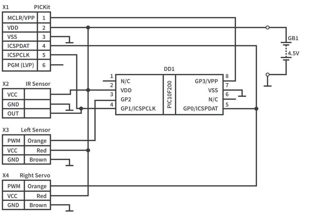
The schematic diagram of the line following robot is shown in figure 2. It’s very similar to the previous one, we just replaced the HC-06 module with the IR sensor module.

The algorithm of the operation of this robot is very simple but effective. As we have only one sensor, we will not follow the line itself but the edge between the black line and the light surface. I programmed the robot to control the left edge of the line, So, when you put your robot on the track, you should place the sensor on the left edge of the line (see figure 3).

Also, please note that this time the robot will move backwards (compared to our last tutorial) because the sensor should be in front of the robot.
As for the track itself, I just took some dark tape (I had dark blue) and attached it to the floor in two rows to make the line wider. The result is shown in figure 4.

But let’s return to the algorithm. When the sensor is located above the line its output is 0, otherwise it gives 1. Also we agreed that we will control the left line edge. That means that if the sensor is above the line we need to rotate the robot left until there is normal floor above the sensor. At this moment we need to reverse the rotation of the robot to the right until the sensor finds the line again. Thus we will move with such zigzags, always oscillating around the left line edge.
Let’s now consider the code that implements the current algorithm:
#include "p10f200.inc"
	__CONFIG _WDT_OFF & _CP_OFF & _MCLRE_OFF

i   		 EQU 10   	 ;Delay register 1
j   		 EQU 11   	 ;Delay register 2
servo1   	 EQU 12   	 ;Servo1 pulse width
servo2   	 EQU 13   	 ;Servo2 pulse width

	ORG 0x0000
INIT
	MOVLW ~(1<<T0CS)
	 OPTION   			 ;Enable GP2
	MOVLW ~((1 << GP0) | (1 << GP2))
	TRIS GPIO   		 ;Set GP0 and GP2 as outputs
LOOP
    BTFSC GPIO, GP1   	 ;Check if GP1 is low (sensor is above the line)
    GOTO MOVE_RIGHT   	 ;If not then go to the MOVE_RIGHT label
MOVE_LEFT   			 ;Move the robot to the left
    MOVLW D'200'   	 ;Load the delay value for the servo 1
    MOVWF servo1
    MOVLW D'215'   	 ;Load the delay value for the servo 2
    MOVWF servo2
    GOTO CONTROL_SERVO    ;Go to the CONTROL_SERVO label
MOVE_RIGHT   			 ;Move robot to the right
    MOVLW D'206'   	 ;Load the delay value for the servo 1
    MOVWF servo1
    MOVLW D'220'   	 ;Load the delay value for the servo 2
    MOVWF servo2
CONTROL_SERVO   		 ;Control the servo 1
    BSF GPIO, GP2   	 ;Set GP2 high
    MOVLW D'2'   		 ;Load 2 into the second delay register 'j'
    MOVWF j
    MOVF servo1, W   	 ;Copy the value of the servo1 into the W
    CALL DELAY   		 ;and call the delay
    BCF GPIO, GP2   	 ;Then seth GP2 low
    NOP   				;One cycle delay before the BSF instruction
SERVO_2   				 ;Control the servo 2
    BSF GPIO, GP0   	 ;Set GP0 high
    MOVLW D'2'   		 ;Load 2 into the second delay register 'j'
    MOVWF j
    MOVF servo2, W   	 ;Copy the value of the servo2 into the W
    CALL DELAY   		 ;and call the delay
    BCF GPIO, GP0   	 ;Then seth GP0 low
PAUSE   				 ;Pause between the pulses
    MOVLW D'25'   		 ;Load 25 into the second delay register 'j'
    MOVWF j
    CALL DELAY   		 ;and call the delay
	GOTO LOOP   		 ;Return to the 'LOOP' label

DELAY   				 ;Start DELAY subroutine here
    MOVWF i   			 ;Load the W value into the 'i' register
DELAY_LOOP
    DECFSZ i, F   		 ;Decrement i and check if it is not zero
    GOTO DELAY_LOOP   	 ;If not, then go to the DELAY_LOOP label
    DECFSZ j, F   		 ;Decrement j and check if it is not zero
    GOTO DELAY_LOOP   	 ;If not, then go to the DELAY_LOOP label
    RETLW 0   			 ;Else return from the subroutine

	END
The program is quite short and, by this time, probably quite obvious to you. Let’s briefly look through it, though, just in case there are lingering questions.
The first thing that you may notice is that this time we didn’t use the timer. I mentioned in the previous tutorial, and will repeat here, that with the timer we can achieve a pulse resolution of about 128us. The real speed control of the servo can be made only within 100us from the middle value 1.5ms, so we need greater resolution than the timer can provide. So we will use good ol’ delays, moreover, there are no concurring time-dependent processes in this device, so there’s really no need.
I will skip the whole initialization part because we’ve already considered everything many times, and will start with the main loop of the program.
    BTFSC GPIO, GP1   	 ;Check if GP1 is low (sensor is above the line)
    GOTO MOVE_RIGHT   	 ;If not then go to the MOVE_RIGHT label
MOVE_LEFT   			 ;Move the robot to the left
    MOVLW D'200'   	     ;Load the delay value for the servo 1
    MOVWF servo1
    MOVLW D'215'   	     ;Load the delay value for the servo 2
    MOVWF servo2
    GOTO CONTROL_SERVO   ;Go to the CONTROL_SERVO label
MOVE_RIGHT   			 ;Move robot to the right
    MOVLW D'206'   	     ;Load the delay value for the servo 1
    MOVWF servo1
    MOVLW D'220'   	     ;Load the delay value for the servo 2
    MOVWF servo2
In line 16, we check the state of the GP1 pin to which the IR sensor is connected. If it’s high, that means we are above the floor and we need to move to the right, which is what we execute in lines 24-28. Otherwise, we need to move to the left and execute the code in lines 18-23.
These two groups ‘MOVE_LEFT’ and ‘MOVE_RIGHT’ are almost the same, we just put the different values into the ‘servo1’ and ‘servo2’ registers. I should mention here that I chose these values in an experimental way. The servos and the microcontrollers may deviate from these parameters, so you probably will need to adjust these values. What you should get is the following: when you need to rotate to the left, the right track should move about 3-4 times faster than the left track, and vice versa. The “inactive” track should still move but very, slowly just so that the robot is constantly moving forward and it also smooths the zigzags.
CONTROL_SERVO   		 ;Control the servo 1
    BSF GPIO, GP2   	 ;Set GP2 high
    MOVLW D'2'   		 ;Load 2 into the second delay register 'j'
    MOVWF j
    MOVF servo1, W   	 ;Copy the value of the servo1 into the W
    CALL DELAY   		 ;and call the delay
    BCF GPIO, GP2   	 ;Then seth GP2 low
    NOP   				 ;One cycle delay before the BSF instruction
After we load the proper values into the ‘servo1’ and ‘servo2’ registers, we move to the ‘CONTROL_SERVO’ part (line 29). We will set the pulses for both servos one after the other: first we will provide the pulse to servo 1 (lines 30-36) and then to the servo 2 (lines 37-43), and finally we will have a pause between the pulses of about 20ms (lines 44-47). I think this part doesn’t need any additional explanation, everything is clear from the comments.
SERVO_2   				 ;Control the servo 2
    BSF GPIO, GP0   	 ;Set GP0 high
    MOVLW D'2'   		 ;Load 2 into the second delay register 'j'
    MOVWF j
    MOVF servo2, W   	 ;Copy the value of the servo2 into the W
    CALL DELAY   		 ;and call the delay
    BCF GPIO, GP0   	 ;Then seth GP0 low
PAUSE   				 ;Pause between the pulses
    MOVLW D'25'   		 ;Load 25 into the second delay register 'j'
    MOVWF j
    CALL DELAY   		 ;and call the delay
	GOTO LOOP   		 ;Return to the 'LOOP' label
And that’s all! This time we did it really fast. Well, now we know the drill and don’t need to chew through every line.
Now you can program your microcontroller, assemble the robot according to figure 2, put the IR sensor module into the “tail” (which surprisingly becomes the head this time) and power the robot.
First, you will need to adjust the IR sensor potentiometer position to get clear readings out of the sensor when it’s above the line, and above the normal surface. This sounds easy but in reality, even a tiny movement of the potentiometer shaft makes the operation unpredictable. Also, the 3D printed cover also affects the sensor readings. So believe me, you will have a harsh time adjusting it. Just a warning.
After you finally adjust the sensor, and consider the results satisfactory, you will need to adjust the values that you load into the ‘servo1’ and ‘servo2’ registers in lines 19, 21, 25, 27. And then you will think that the adjustment of the potentiometer was trivial. Hopefully the values I provide will work well for you and you will not need to suffer the same as I did.
MOVE_LEFT   			 ;Move the robot to the left
    MOVLW D'200'   	     ;Load the delay value for the servo 1
    MOVWF servo1
    MOVLW D'215'   	     ;Load the delay value for the servo 2
    MOVWF servo2
    GOTO CONTROL_SERVO   ;Go to the CONTROL_SERVO label
MOVE_RIGHT   			 ;Move robot to the right
    MOVLW D'206'   	     ;Load the delay value for the servo 1
    MOVWF servo1
    MOVLW D'220'   	     ;Load the delay value for the servo 2
    MOVWF servo2
When you finally adjust everything you can put the robot on the track and let it move alone. If you did everything correctly, it will follow all the curves of the line. If not, check if the sensor works correctly, then make sure it doesn’t move too fast, as in this case it can lose the line.
I don’t even know if it makes sense to provide any statistics. We haven’t learned any new instructions for 3 tutorials. The code size is just 38 words (so much fun in such a tiny amount of memory space).
I don’t give you any homework this time because adjustment of the robot will take enough time. You also can experiment with the different speeds, track configurations, line widths etc. to see how these parameters affect the robot movements. Good luck and have fun!
Check Yourself
10 Questions

Get the latest tools and tutorials, fresh from the toaster.


