LED Blink Control Using Button: A Beginner Project | Renesas RL78 - 3
Published
Hi! Welcome back again to CircuitBread. In our previous tutorial, we installed the e2 studio IDE, GCC for Renesas RL78, and other tools that we can use to develop RL78 projects. In this tutorial, we are going to create our first simple project. I hope you have already purchased the hardware needed. I’ve mentioned in the second tutorial that I’m going to use the RL78/G14 fast prototyping board but you can use a CPU board and a separate programmer/debugger (E2 or E2 Lite Emulator) if you want. I will be using the RL78/G14 FPB as it is cheaper and easy to use. Before we run e2 studio and create our first project, let’s check the RL78/G14 FPB first.
RL78/G14 FPB Unboxing

The box of the RL78/G14 FBP as shown in figure 1 is small and what’s included inside the box is, of course, the RL78/G14 FBP, a guide that I can’t read (I think it’s Chinese), and a quick start guide. That’s all. The box does not include a USB cable unlike in starter or demonstration kits, or in RA evaluation kits. But if you have a micro-USB type B to USB-A cable, you can use it to connect the RL78/G14 FPB to your computer.

Figure 2 shows the top side of the RL78/G14 FPB and before we create our first project, we need to examine the board first and take note of the components mounted on this board. If you’re not using this board, you can skip this part.

- RL78/G14 MCU
The first component that we should check is the RL78/G14 MCU. We need to identify its part number as we need it later when we configure the project. We can see the part number in figure 3 but to be sure, let’s open the user’s manual and check the board specification table: RL78/G14 FPB Board Specification Table. So the part number of the RL78/G14 MCU mounted on this board is R5F104MLAFB which is an 80-pin, 512KB flash memory, 48KB RAM, 8KB data flash memory device.

- USB Connector
The USB connector mounted on the RL78/G14 FPB is a micro-USB type B connector. You can use it to connect to the IDE (e2 studio or CS+) or Renesas Flash Programmer tool and also power the board with the host’s power supply.

- ACT, Power, and User LEDs
The ACT LED is a green LED that shows the emulator control software operation state. If it is illuminated, this indicates that the emulator is connected to the target. If it is OFF, it means that the emulator can’t be used for some reason and if the ACT LED is blinking, this means that the host PC has recognized the emulator. The Power LED is also a green LED which, of course, is illuminated when the board is supplied with power. There are two user LEDs here, LED0 and LED1. These LEDs are connected to Pin 6 (port P43) and Pin 5 (port P44), respectively and can be used for any purpose.

- PmodTM Connectors
The RL78/G14 FPB includes 2 Pmod connectors (6x2 Headers). If you have Pmod devices with a type 2A interface, you can connect those devices to these connectors. However, there’s a note about the serial ports in the user’s manual. So if you’re planning to use these connectors, check the user’s manual of the RL78/G14 FPB first.

- ArduinoTM Connectors
If you try to observe the arrangement of J5, J6, J7, and J8 headers, it was arranged similar to the arrangement of the headers in the Arduino Uno R3. So you can connect your Arduino shields to the RL78/G14 FPB too. However, Renesas doesn’t guarantee connection to all types of Arduino shields. So some shields may not work.

- Clock
For this FPB, only a 32.768kHz crystal oscillator (X1) is mounted. It is actually for the sub-clock. So for the main system clock, we will use the high-speed on-chip oscillator (HOCO).

- Reset and User Switches
There are two switches mounted on the RL78/G14 FPB, SW_RST (Reset Switch) and SW_USR (User Switch). The SW_RST switch is for applying a hardware reset to the RL78/G14 MCU while the SW_USR switch which is connected to Pin 13 (P137) can be used for any purpose.
.")
- MCU Headers
J1 and J2 (see figure 11), which are not mounted, are two 20x2 headers connected to all the pins of the MCU. You can solder male or female headers (pitch: 2.54 mm) if you want to access the MCU pins that are not connected to the mounted headers.

- Emulator Reset Header
The emulator can be put in a forced reset state (which allows stand alone operation of the RL78/G14 MCU) by short-circuiting the emulator reset header (EJ1). You can solder a 2-pin male header so you can easily short the pins.

- Power-Supply Selection Header
The default operating voltage of the RL78/G14 FPB is 3.3V. You can change the operating voltage (5V or 3.3V) but you need to modify the board. The power-supply selection header (J4) should be mounted (see figure 13) and the SS11 pattern should be cut (see figure 14). According to the RL78/G14 FPB user’s manual, if an Arduino shield is to be connected, the SS1 pattern should be cut and the SC1 pattern should be short-circuited (see figure 14).
Figure 15 shows the schematic diagram of the power-supply selector. As you can see, to select VBUS or 5V power supply, we should short pin 2 and pin 3 of the header J4. If you’re going to use 3.3V, short pin 1 and pin 2 of the header J4 or just don’t modify the board because 3.3V is initially selected by the SS11 pattern.


- External Power Supply Header
The R5F104MLAFB RL78/G14 MCU can operate from 1.8V to 5.5V. So if you want to use an operating voltage other than 3.3V or 5V, you can use the external power supply header (J3). When you use this header, don’t forget the SS11 pattern. You should still cut it. You also need to short-circuit the emulator reset header (EJ1). If you’re going to supply power through the external power supply header, you can’t use an Arduino shield if the power being supplied is not 3.3V.

- Coin-Cell Battery Holder
You can use a CR2032 battery to power the RL78/G14 FPB. However, you still need to mount the U2, U3, C9, C12, and L1 components. Please check the RL78/G14 FPB BOM List to see the recommended parts. If you use a coin-cell battery, you should cut the SS11 pattern and short-circuit the emulator reset header (EJ1).

As you can see in figure 18, I’ve mounted the two 20x2 MCU female header because I want access to all pins of the MCU. I’ve also mounted the emulator reset header, the power supply selector header, and the external power supply header.

We will use 5V operating voltage in this tutorial series so I cut the SS11 pattern but since I’m not going to use any shields, I didn’t touch the SS1 and SC1 patterns.

However, I have trust issues, so I’ve measured TARGET_VCC to be sure it’s okay to leave the SS1 and SC1 patterns untouched and yes, we’re getting a VBUS (~5V) level when pin 2 and pin 3 of J4 are shorted. When pin 1 and pin 2 are shorted, we’re getting ~3.3V.


So we are done checking the RL78/G14 FPB. Let’s open e2 studio and create our first project.
Creating the Project in e2 studio

To create a project, after opening e2 studio, let’s close the welcome page first and then click the File menu and select New >> Renesas C/C++ Project >> Renesas RL78.

Now we’re going to select a template and since we’re going to use the GCC compiler, let’s choose GCC for Renesas RL78 C/C++ Executable Project and click the Next button.

Next, we will be asked for the project name and here I named the project RL78_G14_FPB_First_Project. If you want to choose another name, that’s up to you. I actually don’t know the naming rules but don’t worry, an error message will appear if you used characters that are invalid.

After selecting a project name, we are going to set the toolchain, device, and debug settings. So for the toolchain settings, we set the language to C, the toolchain to GCC for Renesas RL78, and the version of the GCC we’ve previously installed. In the device settings, by default the target board is set to Custom so let’s just leave it like that. But for the target device, we should change it to the part number of the RL78/G14 MCU used in the RL78/G14 FPB. Let’s click the … button.

Then select RL78/G14.

Then select the 80-pin list and the part number R5F104ML.

Next, let’s set the debug settings and change the emulator to E2 Lite since the on-board emulator of the RL78/G14 FPB acts like an E2 Lite emulator. After setting the emulator, we are supposed to click the Finish button. But we’re not going to do that yet. We’re going to click the Next button as we need to use the Peripheral Code Generator.

We need the help of the code generator to generate macro definitions and code for initializing the hardware. Doing it manually takes a lot of time and honestly I’m still not familiar with the initialization of the RL78 MCU. So let’s check Use Peripheral Code Generator and click the Finish button. Actually, you can still click the Next button to select Additional CPU Options and select Library Generator Settings. But we are not changing those settings. So let’s click the Finish button to create the project.


Hardware Initialization using Code Generator
We now have an RL78 project. But it’s empty. So the next thing that we are going to do is to initialize the hardware and as previously mentioned, we’re going to use the Code Generator for that. In the Project Explorer window, let’s click the collapse button to find the Code Generator.

Double click Code Generator and then double click the Peripheral Functions to open the Code Generator.

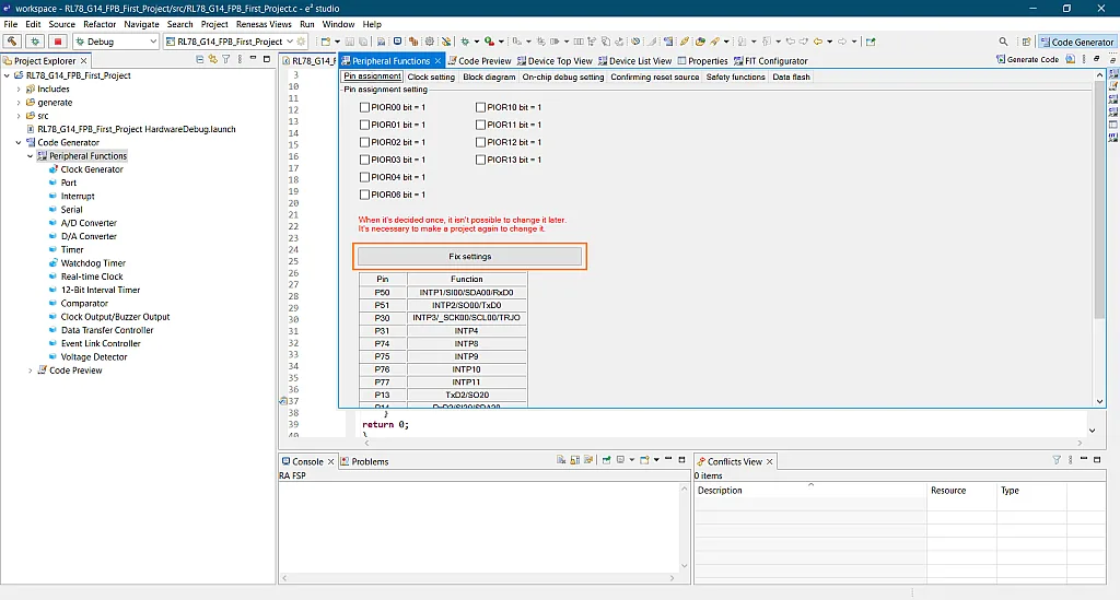
Under the Pin assignment tab (see figure 33), let’s click the Fix settings button to assign the function of the pins. We will not change anything for now but maybe later we need to change some of the functions assigned to the pins. But for now let’s just click the button and proceed to the Clock setting tab.

We are using a 5V operating voltage so for the Operation mode setting and EVDD setting, let’s select High speed main mode 3.6 (V) ≤ VDD ≤ 5.5 (V) and 4.0 (V) ≤ VDD ≤ 5.5 (V), respectively. For the main system clock, let’s select High-speed OCO and set the frequency to 64MHz under High-speed OCO clock setting.

Next, we are going to disable the Watchdog Timer as we don’t need it for now and by default the code generator enables it. So let’s click this very noticeable Menu button (that’s sarcasm, by the way).

Then click Watchdog Timer.

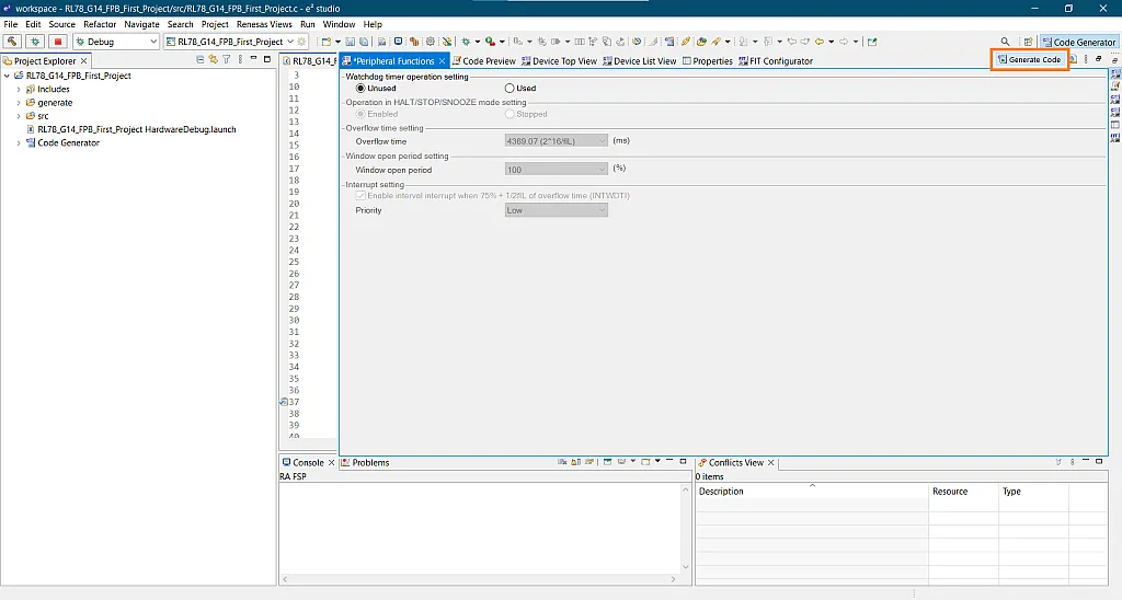
Then check Unused.

And then click Generate Code.

After generating the hardware initialization code, let’s open the src folder in the project explorer and open the r_main.c file.

Okay, so that’s our main file and before we put some code there, let’s set the Debug Configurations first. Just click the down arrow next to the bug icon and then click Debug Configurations… as shown in figure 40.

Now click the Debugger tab.

And then the Connection Settings under the Debugger tab.

Then we set the Power Target From The Emulator (MAX 200mA) to No.

Then hit the Apply and Close buttons.

First Project Code
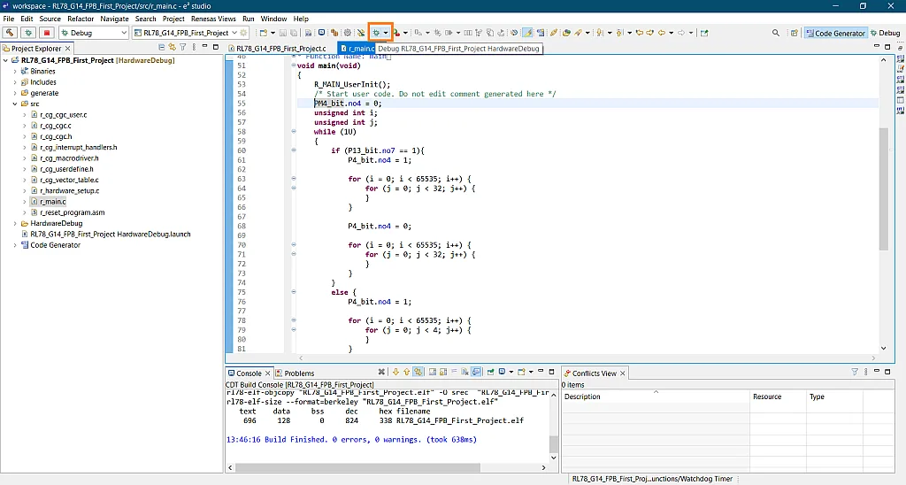
So we’re back to our main file again. I’ve actually prepared a code below that we’ll paste between the two comment lines (line 54 and line 59) inside the main function. We’ll replace the code between those comments.
 Function.")
	PM4_bit.no4 = 0;
	unsigned int i;
	unsigned int j;
	while (1U)
	{
		if (P13_bit.no7 == 1){
			P4_bit.no4 = 1;

			for (i = 0; i < 65535; i++) {
				for (j = 0; j < 32; j++) {
				}
			}

			P4_bit.no4 = 0;

			for (i = 0; i < 65535; i++) {
				for (j = 0; j < 32; j++) {
				}
			}
		}
		else {
			P4_bit.no4 = 1;

			for (i = 0; i < 65535; i++) {
				for (j = 0; j < 4; j++) {
				}
			}

			P4_bit.no4 = 0;

			for (i = 0; i < 65535; i++) {
				for (j = 0; j < 4; j++) {
				}
			}
		}
	}
Here’s the code. For now, let’s not worry about the functions, registers, variables, etc. used in the code. We will discuss them next time. But here’s what it does. The code simply utilizes the on-board LED (LED1) and switch (SW_USR). If the switch is not pressed, the LED will blink at a slow rate. If the switch is pressed, the LED will blink at a faster rate.
 function comment lines.")
So let’s build the project. You can do that by clicking the Project menu and Build All or you can just use keyboard shortcut Ctrl+Alt+B.

After building the project, let’s click the debug icon to start testing the code.

Once the code is uploaded to the MCU, the IDE will ask you to switch to Debug perspective which provides a view more appropriate for debugging. You can switch back to the previous view though by clicking the Code Generator button beside the Debug button. So let’s click the Switch button.

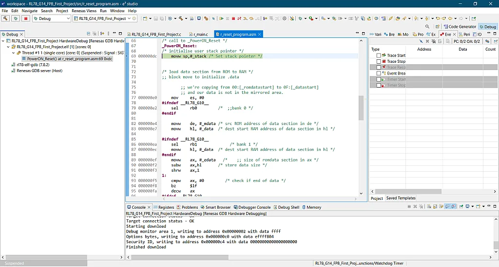
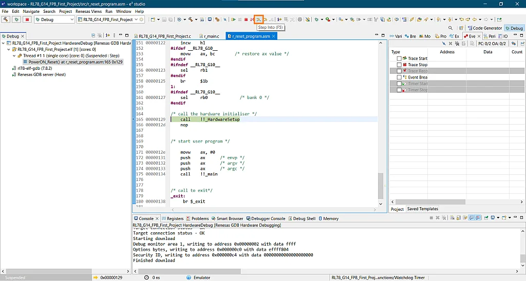
As you can see in the images below, the files r_reset_program.asm, r_hardware_setup.c, r_cg_cgc_user.c, and r_cg_cgc.c are opened and executed to initialize the hardware. You can follow the initialization steps and code by clicking the Step Into button or pressing the F5 function key.


After initializing the hardware, the main function will be called.
 Function.")
So in the r_main.c file, you can just click the Resume button or press the F8 function key to let the program run on its own. Then you’ll see LED1 start blinking. Try pressing SW_USR and you’ll see the LED blinks faster.
 Button.")
When you click the Terminate button, the program actually stops and you might wonder why the board is not running the code when it is powered by the USB port of your computer. Well, this is because of the emulator. Remember the emulator reset header? If you want the board to operate in standalone mode, short the pins of the emulator reset header and the program will run even if you close the IDE.

So this is the end of the tutorial. I hope you were able to follow all the steps on how to modify the RL78/G14 FPB to operate in 5V, create an RL78 project, use the Code Generator to generate codes that initialize the hardware, and use the simple code I provided to test the on-board LED and switch. In the next tutorial, we will discuss RL78 GPIOs to understand the code that we used here. See you next time!

Authored By
JB Magoncia
JB is an Electronics Engineer who is interested in audio, embedded systems, and PCB design. He is one of CircuitBread Engineers. JB is also a musician who mainly plays piano/keyboard but can also play bass, guitar, and drums. He currently lives in Cagayan de Oro, Philippines.

Related Tutorials

Related EE FAQs
 work?")
How do Analog to Digital Converters (ADCs) work?

Answered by Uma Bharathi D

What's the difference between a regular relay and a power relay?

Answered by Jayesh Upadhyay

What is a PWM signal?
Answered by Jayesh Upadhyay

Why is RAM faster than other memories?
Answered by Jayesh Upadhyay
Explore CircuitBread
- 244 Tutorials
- 9 Textbooks
- 12 Study Guides
- 31 Tools
- 104 EE FAQs
- 295 Equations Library
- 213 Reference Materials
- 97 Glossary of Terms
Friends of CircuitBread
-

Free Industry Lead Time Monitor
-

Partner Store With Academic Discount Pricing
-

Product Samples Upon Request


Get the latest tools and tutorials, fresh from the toaster.


