Arduino Compatible Digispark Board - The First Impressions 1.5
Published
Hi! Today I want to finish the Arduino portion of the tutorials because I have already written even more than I expected initially. The last tutorial will be devoted to the Digispark board designed by Digistump. They produce the full ecosystem around their boards and designed a lot of shields, extension boards, and modules. You can find all of them in their shop: Digistump Shop.
Now let’s familiarize ourselves with this tiny yet cool board.
Introduction to the Digispark Board
The official price of the Digispark board is $7.95 USD at the time of writing this tutorial but our Aliexpress friends produce them as well and sell for $1.30-$1.50USD using the same parts. That’s also why this board became very popular.
The Digispark board is produced in two form factors shown in Figure 1 and Figure 2.


The schematic of both boards is the same, the only difference (as follows from Figure 1, 2) is that the blackboard has a USB plug printed on the PCB, while the blue board has a micro-USB socket. The interesting fact is that the official Digispark board has only one version, which is shown in Figure 1.
Anyway, let’s consider what is found on these boards. The core of the Digispark is the ATtiny85 microcontroller, which also belongs to the AVR family of the Atmel (now Microchip) Corp. Let’s compare this board with the Arduino Uno (Table 1)

As you can see, the Digispark is weaker than the Uno board in almost all parameters, so why is it so popular apart from the price?
The reason is that the Digispark board can operate as a USB device. Yes, this is not a joke. People who are familiar with the AVR family know that ATtiny85 doesn’t have the hardware USB module. But there is a special library called V-USB which allows it to emulate the USB1.1 protocol using almost any AVR microcontroller which has at least 2 kB of Flash memory and 128 bytes of RAM (as you can see from Table 1, ATtiny85 satisfies both these demands). You can read about this library in more detail on the official site: ObDev.at - V-USB. Also, you can find there a lot of application examples (VUSB - Example Projects) some of which are quite interesting.
So using this Digispark board you can create USB-applied devices, like keyboard, mouse, joystick, virtual COM-port, etc. When you do this, the two pins (P3 and P4) of the ATtiny85 MCU are used for USB communication, thus you have only four pins left for your needs. And moreover, in the board I have, the P5 pin was configured as the reset pin so I couldn’t use it either, thus leaving only three pins.
If you don’t need the USB functionality, you can use P3 and P4 as you wish. Also, the Digispark has an LDO regulator which allows power to the board with a voltage of 7 to 12 V applied to the VIN pin. As you can see, this LDO uses a significant part of the board space, especially in the black version (Figure 1).
The other reason for Digispark’s popularity is its compatibility with the Arduino. And now let’s consider how to program it using the Arduino IDE.
Adding the Digispark Board to the Arduino IDE
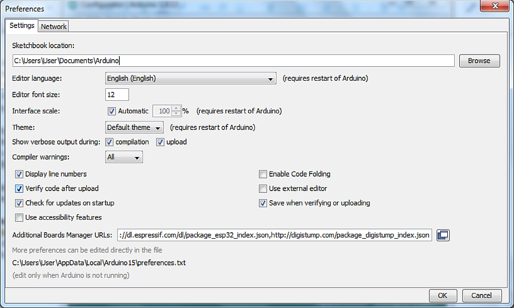
As I told you in the second Arduino tutorial, in the ‘File” menu there is the “Preferences” point which we didn’t consider at that time. And now its time has come. So, please open your Arduino IDE and select the “Preferences”. You will see the following window (Figure 2)

The settings may vary from what you see in Figure 3 but that’s OK. I’ll tell you which ones are important now.
So to add some external board support you need to add it to the “Additional Boards Manager URLs”. As you can see in fig. 3 I have a lot of URLs there but at the moment we don’t need all of them. To add a new board you need to click on the button to the right of the text field which looks like a window. Then you will see another window, in which you should write the text “http://digistump.com/package_digistump_index.json” (Figure 4).

If you ask me where I found this URL, I’ll answer you sincerely: I don’t remember. Probably in one of the many tutorials which are devoted to this topic (and now I’m creating one more 😊 ). But actually, the solution is quite simple if you don’t know the correct URL. You can click on the “Click for a list of unofficial boards support URLs” (surprise, surprise!) and see the large list of third-party boards, where you can find the following line “Digistump (Official): http://digistump.com/package_digistump_index.json”, which is exactly what we need.
After doing this, we can click “OK” in the window in Figure 4 and then in the window in Figure 3.
Now the Arduino IDE knows where to look for the new board, and we can add it in the “Board Manager” from the “Tools” menu. There will be a list of all available boards. You need to find the “Digistump AVR Boards” and install it (Figure 5).

During the installation you will be prompted to install the drivers, please click “Next” in the window to install the drivers for the Digispark board, as they are different from those used in normal Arduino boards.
After closing this window you can open the “Tools” menu and make sure that now you have the “Digistump AVR boards” (Figure 6).

To use the Digispark board we need to select the “Digispark (Default - 16.5mhz)”. After that, we can go to the “File” menu and see that now we have a lot of Digispark examples (Figure 7).

Looks like we have successfully prepared the Arduino IDE, and now it’s time for some practical work.
Testing an Example Project
Let’s open some of the example projects and try to run them. First, let’s open the “Blink” example which we tried in Tutorial 1.3. Even though the Digispark has a very limited number of pins, it still has an on-board user LED connected to pin P1. So we can use it but with some tweaks. When we open this example and try to compile it, it gives an error “'LED_BUILTIN' was not declared in this scope” which means that the macro LED_BUILTIN is not defined for the Digispark board. But as we know that the LED is connected to pin P1 we just replace the ‘LED_BUILTIN’ with ‘1’ and try to compile again. Now everything is fine.
Uploading the sketch into the Digispark board differs from the Arduino boards because they use different bootloaders. For me, the uploading method with Digispark is a bit inconvenient but we have what we have. To upload the sketch you need to remove the board from the USB port, then press the “Upload” button. In some seconds it will tell you
“Running Digispark Uploader...
Plug in device now... (will timeout in 60 seconds)”
This means that now you need to plug the board within 60 seconds. When you do this, the bootloader starts in the ATtiny85 MCU and waits to see if the PC app wants to update the firmware. If nothing happens within 3 seconds, the previously loaded user program starts to execute. This is another inconvenience: when you power-up the board, you need to wait for several seconds before the bootloader gives up control to your program.
But if we plug the board when the PC app is waiting for it, the bootloader will upload the code into the MCU’s flash memory and then run it. So after we connect the Digispark to the PC, the uploading will start, and then you will see that the user LED blinks on the board, which means that everything went fine.
But let’s now open and run a USB-related example. To be specific, let it be the “DigisparkKeyboard”. The code of this example is listed below:
#include "DigiKeyboard.h"

void setup() {
  // don't need to set anything up to use DigiKeyboard
}


void loop() {
  // this is generally not necessary but with some older systems it seems to
  // prevent missing the first character after a delay:
  DigiKeyboard.sendKeyStroke(0);

  // Type out this string letter by letter on the computer (assumes US-style
  // keyboard)
  DigiKeyboard.println("Hello Digispark!");

  // It's better to use DigiKeyboard.delay() over the regular Arduino delay()
  // if doing keyboard stuff because it keeps talking to the computer to make
  // sure the computer knows the keyboard is alive and connected
  DigiKeyboard.delay(5000);
}
Actually, if we remove the comments, the useful code will span just 6 lines. First, we need to include the “DigiKeyboard.h” library (line 1). It contains all necessary code to emulate the USB keyboard. As you see, the setup part is empty now (lines 3-5), so most of the code is hidden in the library.
In the loop part (lines 8-21) do just 3 actions which are described in the comments in code above.
So let’s try and run this example. Click on the “Upload” button and remove the Digispark board, wait for the prompt to connect the board, and then plug it again. Wait for some seconds while the program is being uploaded, and then open any text editor. You will see that the text “Hello Digispark!” is typed again and again in the new line every 5 seconds, which means that everything works fine, too.
If you are curious enough you can scroll up the output window of the Arduino IDE and see the following information:
“Sketch uses 2810 bytes (46%) of program storage space. Maximum is 6012 bytes.
Global variables use 106 bytes of dynamic memory.”
This means that the hidden code is large enough to spend about half of the available Flash memory. And this is not surprising: the USB protocol is complex when emulated in software.
And that’s all I wanted to tell you about the Digispark in particular and the Arduino in general. If you are interested in the Digispark board, you can read more about it in the official Wiki: DigiSpark.
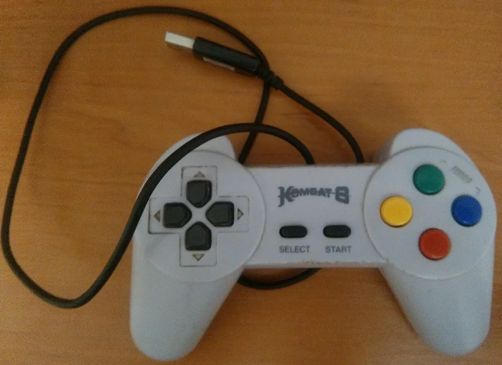
By the way, I recently made a converter from an old NES gamepad to USB using the Digistump board and the modified “DigisparkJoystick” example (Figure 8 and 9). Then I spent several happy hours playing old-school 8-bit games from my childhood. So even such a tiny board can make you happy if you know how to use it. 😉


And now that’s really it! Next time we will start with the Raspberry Pi single-board computer, so stay with us! See you soon!

Get the latest tools and tutorials, fresh from the toaster.


