Arduino Programming Language - The First Impressions 1.3
Published
Hi! Previously, we've discussed Arduino IDE Interface - The first impressions 1.2! So, today we will continue studying the Arduino platform and the Arduino Programming Language. And this time we will talk a bit about the Arduino programming language itself. I will assume that you already are familiar with the C-like languages and don’t need any explanations on their syntax.
You may click here for the first part.
Arduino Programming Language
The Arduino programming language is based on C/C++. Which means you can use (and create when you are experienced enough) classes to make the code more readable.
The first impression when you look at the Arduino code is “Wow! That looks really simple!”. The thing is that I started with Arduino after programming different controllers without any libraries, so I had to directly manipulate the microcontrollers register. And here I saw the intuitive functions, like pinMode, AnalogRead, DigitalWrite etc. They make life for a programmer much easier. I don’t want to complain that there is a lot of excessive code inside these functions to make them universal, as this is the sacrifice for simplicity.
You can familiarize yourself with the main functions, constants, variables and structure elements of the Arduino programming language (I’ll call it the Arduino langue) here: Arduino Language Reference
Blank Arduino Program
Now, let’s see what Arduino offers us by default. When you create a new sketch, it looks like this:
void setup() {
// put your setup code here, to run once:

}

void loop() {
// put your main code here, to run repeatedly:

}
As you can see, there are two empty functions: setup (lines 1-4) and loop (lines 6-9). The setup function (as follows from the comment in line 2) is invoked only once after resetting the MCU, while the loop function is invoked repeatedly while the MCU is powered, in an endless loop.
So in the setup function, you write the initialization part of the code: configurations of the inputs/outputs, peripheral modules, external libraries, etc. In the loop function, you write what you want your MCU to do repeatedly.
The attentive readers may wonder why there is no main function that is always present in the C/C++ language. The thing is that Arduino hides it from you. When you press the button “Verify”, it creates a temporary file with the extension ‘cpp’ and copies your code into certain places, and this file does have the main function and some other code. To prove this, please press the “Verify” button and wait for the result of the compilation. You will see the following:
“Sketch uses 444 bytes (1%) of program storage space. The maximum is 32256 bytes.
Global variables use 9 bytes (0%) of dynamic memory, leaving 2039 bytes for local variables. Maximum is 2048 bytes.“
So even though you didn’t write any character of the code, the blank program already spends 444 bytes of Flash memory and 9 bytes of RAM. The explanation of how these bytes are used is beyond the scope of this tutorial, you can take a look at the native Arduino code here: GitHub > ArduinoCore-avr (you have this folder on your PC after installing the IDE as well, but it’s really hard to find it).
Simple Arduino Example
OK, now let’s open the Blink example from the previous tutorial and try to understand it:
/*
  Blink

  Turns an LED on for one second, then off for one second, repeatedly.

  Most Arduinos have an on-board LED you can control. On the UNO, MEGA and ZERO
  it is attached to digital pin 13, on MKR1000 on pin 6. LED_BUILTIN is set to
  the correct LED pin independent of which board is used.
  If you want to know what pin the on-board LED is connected to on your Arduino
  model, check the Technical Specs of your board at:
  https://www.arduino.cc/en/Main/Products

  modified 8 May 2014
  by Scott Fitzgerald
  modified 2 Sep 2016
  by Arturo Guadalupi
  modified 8 Sep 2016
  by Colby Newman

  This example code is in the public domain.

  http://www.arduino.cc/en/Tutorial/Blink
*/

// the setup function runs once when you press reset or power the board
void setup() {
  // initialize digital pin LED_BUILTIN as an output.
  pinMode(LED_BUILTIN, OUTPUT);
}

// the loop function runs over and over again forever
void loop() {
  digitalWrite(LED_BUILTIN, HIGH);   // turn the LED on (HIGH is the voltage level)
  delay(1000);                   	// wait for a second
  digitalWrite(LED_BUILTIN, LOW);	// turn the LED off by making the voltage LOW
  delay(1000);                   	// wait for a second
}
Well, the program is long but the majority are in the comments (lines 1-23). Here you can read useful information about the project name (line 2), its brief description (line 4), and the detailed description (lines 6-11), revisions and authors (lines 13-18), licensing information (line 20), and the link where you can find more information about the project (line 22).
The program itself is located in lines 25-37. I frankly don’t see any reasons to explain it. The comments and the function names are extremely clear. If still, something is confusing, you can always open the link provided in line 22: Tutorial - Blink and read the comprehensive information about it there.
As I mentioned, my idea is not to teach you how to program on Arduino but to show how simple it is. The Arduino isn’t the most popular platform for no reason, it has very good and clear support that allows you to program it regardless of your programming and electronics level and skills.
Also, as I mentioned, the Arduino has a bunch of different hardware expansion modules and shields, for each of which you can find the corresponding library.
More Advanced Example
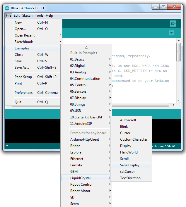
Let’s now try to connect the 1602 LCD which we used in this corresponding tutorial about the PIC10F200. As this LCD is very popular, there is even a built-in library for using it, called LiquidCrystal. So let’s try an example from it, for instance, “Serial display” (Figure. 1)
/*
  LiquidCrystal Library - Serial Input

 Demonstrates the use of a 16x2 LCD display.  The LiquidCrystal
 library works with all LCD displays that are compatible with the
 Hitachi HD44780 driver. There are many of them out there, and you
 can usually tell them by the 16-pin interface.

 This sketch displays text sent over the serial port
 (e.g. from the Serial Monitor) on an attached LCD.

 The circuit:
 * LCD RS pin to digital pin 12
 * LCD Enable pin to digital pin 11
 * LCD D4 pin to digital pin 5
 * LCD D5 pin to digital pin 4
 * LCD D6 pin to digital pin 3
 * LCD D7 pin to digital pin 2
 * LCD R/W pin to ground
 * 10K resistor:
 * ends to +5V and ground
 * wiper to LCD VO pin (pin 3)

 Library originally added 18 Apr 2008
 by David A. Mellis
 library modified 5 Jul 2009
 by Limor Fried (http://www.ladyada.net)
 example added 9 Jul 2009
 by Tom Igoe
 modified 22 Nov 2010
 by Tom Igoe
 modified 7 Nov 2016
 by Arturo Guadalupi

 This example code is in the public domain.

 http://www.arduino.cc/en/Tutorial/LiquidCrystalSerialDisplay

*/

// include the library code:
#include <LiquidCrystal.h>

// initialize the library by associating any needed LCD interface pin
// with the arduino pin number it is connected to
const int rs = 12, en = 11, d4 = 5, d5 = 4, d6 = 3, d7 = 2;
LiquidCrystal lcd(rs, en, d4, d5, d6, d7);

void setup() {
  // set up the LCD's number of columns and rows:
  lcd.begin(16, 2);
  // initialize the serial communications:
  Serial.begin(9600);
}

void loop() {
  // when characters arrive over the serial port...
  if (Serial.available()) {
	// wait a bit for the entire message to arrive
	delay(100);
	// clear the screen
	lcd.clear();
	// read all the available characters
	while (Serial.available() > 0) {
  	// display each character to the LCD
  	lcd.write(Serial.read());
	}
  }
}
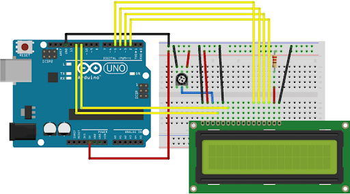
And again, the main part of the code is in the comments with its description. Also, these comments have the connection description (lines 11-21). If it’s not enough for you, you still can open the link Liquid Crystal Serial Display (line 36) and read a very detailed explanation of this example there. There are also the schematic diagram and the Fritzing connection diagram (Figure. 2)
This project uses the library LiquidCrystal, which we need to add to our project by means of the #include directive (line 41). After that, we can create the object ‘lcd’ of class ‘LiquidCrystal’ with the specified connection parameters (line 46), after that we can use all the methods of this class.
In the setup function, we just call ‘lcd.begin(16, 2)’ (line 50) and ‘Serial.begin(9600)’ (line 52) to initialize and start the LCD display and the serial COM port, respectively. This is amazing, only two lines! If you read the PIC10F200 tutorials, you can see how many lines we spend for this (even though the produced machine code was much smaller).
In the loop function (lines 55-68) we check to see if there are some characters on the serial port (line 57) and then after waiting for the whole message (line 59) we read it character-wise and display it on the LCD (lines 63-65).
And that’s it! Everything is very clear, and functions are similar to a normal programming language, which makes them easily understandable.
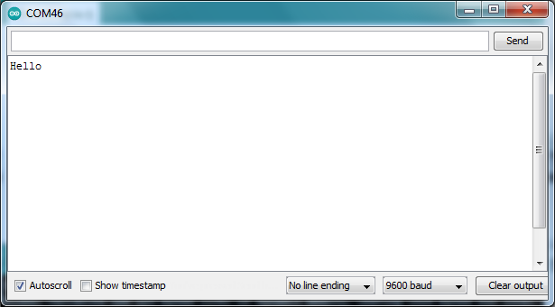
Let’s now do the practical work. Please connect your LCD according to fig. 2, then connect your Arduino board to the PC, open the corresponding sketch (fig. 1) and upload it to your board. Now we need to send the message to the LCD via the serial port. It’s very easy - you just need to open the Serial Monitor (see the previous tutorial), type your message there and press the “Send” button (Figure 3).
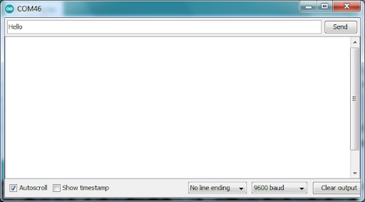
After sending the message it will not appear in the large field below because there you can only see the incoming messages. If you want, you can echo your message by changing the code in lines 63-66:
while (Serial.available() > 0) {
	// read each character from the serial buffer
	char c = Serial.read();
  	// display the read character to the LCD
  	lcd.write(c);
	// send back the character
	Serial.write(c);
	}
After changing the code and uploading it to the Arduino board, you will see, that echo works fine (Figure 4).
If you look at the list of code examples, you may see that it’s quite limited. But what do you do if you want to add some new module which is not listed there? Let me show you how to do this.
Adding New Module
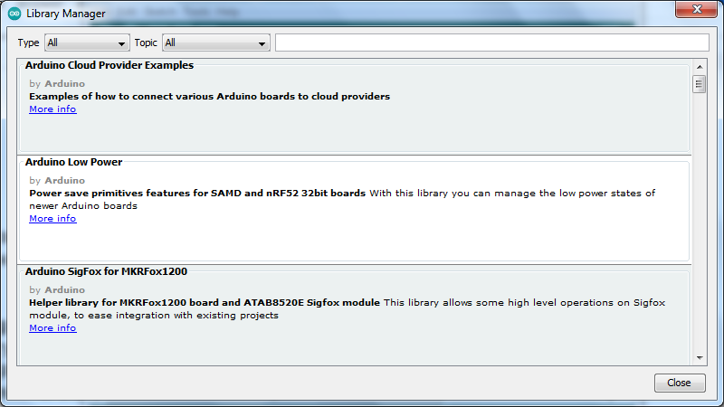
Let’s try to connect the DS18B20 sensor which we used in this tutorial about a digital thermometer. First, we need to add the corresponding library. To do this we open Arduino IDE, then select the point “Manage libraries…” in the “Tools” menu. You will see the following window (Figure 5).
Now, to make the search easier, you can select the “Type” as “Arduino”, and the “Topic” as “Sensor”. Then we type “ds18b20” in the field “filter your search” and press Enter. You will see some libraries, you can read their description and select the one you like. To be specific, let’s select the “DallasTemperature” library at the top (Figure 6).
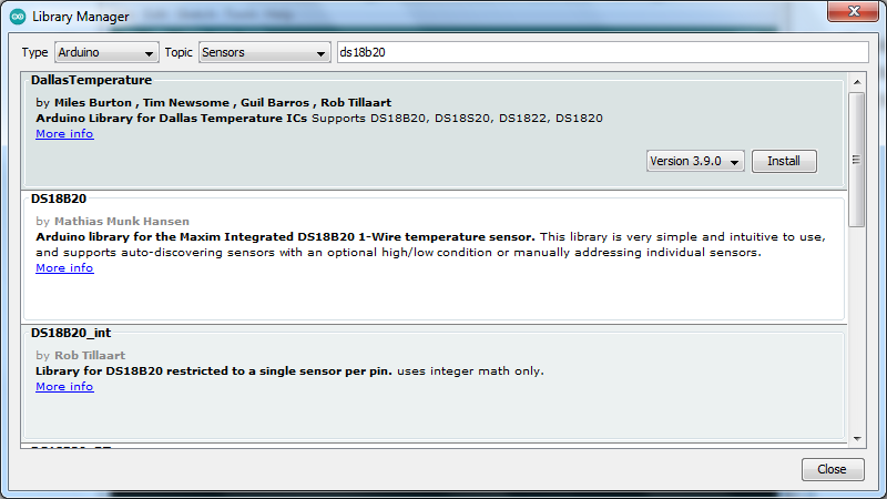
It will give you a warning that it requires the dependent library “OneWire” and ask to install it as well, so if you don’t want to have any problems, you’d better agree and select “Install all”.
In a few seconds, the library will be installed. Now, you can close the Library Manager and go to the “Examples” point from the “File” menu. You will see the new “DallasTemperature” point there in the section “Examples from custom libraries” (Figure 7). Open it and select “Simple”.
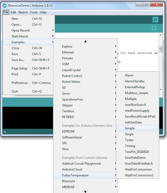
You will see the following code:
/// Include the libraries we need
#include <OneWire.h>
#include <DallasTemperature.h>

// Data wire is plugged into port 2 on the Arduino
#define ONE_WIRE_BUS 2

// Setup a oneWire instance to communicate with any OneWire devices (not just Maxim/Dallas temperature ICs)
OneWire oneWire(ONE_WIRE_BUS);

// Pass our oneWire reference to Dallas Temperature.
DallasTemperature sensors(&oneWire);

/*
 * The setup function. We only start the sensors here
 */
void setup(void)
{
  // start serial port
  Serial.begin(9600);
  Serial.println("Dallas Temperature IC Control Library Demo");

  // Start up the library
  sensors.begin();
}

/*
 * Main function, get and show the temperature
 */
void loop(void)
{
  // call sensors.requestTemperatures() to issue a global temperature
  // request to all devices on the bus
  Serial.print("Requesting temperatures...");
  sensors.requestTemperatures(); // Send the command to get temperatures
  Serial.println("DONE");
  // After we got the temperatures, we can print them here.
  // We use the function ByIndex, and as an example get the temperature from the first sensor only.
  float tempC = sensors.getTempCByIndex(0);

  // Check if reading was successful
  if(tempC != DEVICE_DISCONNECTED_C)
  {
	Serial.print("Temperature for the device 1 (index 0) is: ");
	Serial.println(tempC);
  }
  else
  {
	Serial.println("Error: Could not read temperature data");
  }
}
As you can see, this time the code is not as well commented as the native ones. Even if you go to the arduino.cc site and find the documentation of this library, you will see that it’s quite poor: DallasTemperature Arduino Library.
But fortunately, we still have the examples and the intuitive function names. Let’s try to understand what happens here.
In lines 2 and 3 we include the required libraries: OneWire (to work with the 1-wire interface itself), and DallasTemperature (to work with the temperature sensors of Dallas Semiconductors (now Maxim)). In line 6, we define that we connect the DS18B20 sensor to the digital pin #2 of the Arduino board. In line 9 we define the object ‘oneWire’ of the class ‘OneWire’, and in line 12 we use this object to initialize the object ‘sensors’ of the class ‘DallasTemperature’.
In the ‘setup’ function (lines 17-25) we just initialize the serial interface (line 20), inform the world what app we’re running (line 21), and start the ‘sensors’ library (line 24).
In the ‘loop’ function (lines 30-51) we initially request the temperature calculation (for details please refer to the tutorial Digital Thermometer - Part 16 Microcontroller Basics (PIC10F200)) by calling the method ‘requestTemperatures’ (line 35).
Then in line 39, we call the method ‘getTempCByIndex’. As I got, this method is used if several sensors are connected to the same bus, and you can choose which sensor to read. If you are attentive enough you should know that there must be a delay of at least 750 ms between requesting the temperature and reading the result but we don’t see it here. I opened the source code and found that the ‘requestTemperatures’ method can block the program until the conversion is done, but this is not mentioned anywhere in the documentation. This is the situation where more knowledge brings more problems: if I didn’t know about this feature, I wouldn’t be surprised at all.
But let’s return to the sketch. After we read the temperature value, we check if it’s not equal to some ‘DEVICE_DISCONNECTED_C’ which seems to be a constant defined in the library, which represents a value that can’t be sent by the sensor to indicate that it is absent (line 42). If the sensor is present, we send the temperature via UART (lines 44, 45). Otherwise, we inform the user that the sensor is absent (line 49).
And that’s about it for this program. There are no schematics or Fritzing diagrams for this example, so you need to invent them yourself. It’s not difficult, the DS18B20 sensor has only 3 wires: VCC (connect to 5V), GND (connect to GND), and DQ (connect to pin 2, as defined in line 6). Also, don’t forget the pull-up resistor of 4.7kOhm between the DQ and VCC pins. I will not draw it, as I hope the description is quite clear.
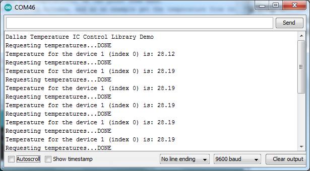
Now let’s compile and upload this sketch into the Arduino board. If you connected everything correctly you can see the following text in the Serial monitor (Figure 8):
Now, let’s comment lines 21, 34, 36, and 44 (all the lines that send something to the UART except for the temperature) and re-upload the sketch. Then let’s open the Serial Plotter from the ‘Tools’ menu and see the graph of the temperature (Figure 9).
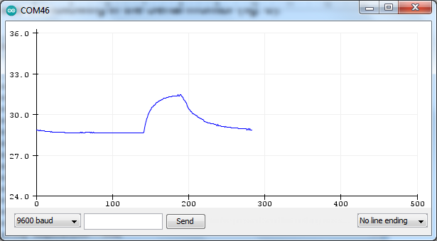
As I mentioned previously, I’d never used the Serial Plotter prior to this. As you can see, even if we don’t understand how certain things work in the Arduino ecosystem, we still can use them, which makes the entrance threshold extremely low: you can use it even with minimal knowledge, which you can improve further though.
Frankly, programming the Arduino is a very large topic, and I can talk about it for hours, but let’s stop on this. I showed you where to read about the in-built examples, how to install the external libraries and use them. So I think you can go on by yourself, it’s not difficult at all.
And even if you don’t like text programming, but know the Scratch language, you can use it for programming the Arduino, and next time I’ll tell you how to do this. See you soon!

Get the latest tools and tutorials, fresh from the toaster.

