Arduino Programming using Scratch - The First Impressions 1.4
Published
Hi! We’re continuing on with the Arduino. I know, I only intended to make three tutorials about each platform but Arduino seems so versatile that I’m fighting the urge to write a full series just about it. But I realize that this would be a waste of time because making ten thousand first tutorials about Arduino is not the best idea. So I’ve limited myself with just five tutorials about it. And here’s the fourth! And as I announced previously, it will be devoted to programming the Arduino using Scratch, and it will be quite short.
Introduction to S4A
I will be honest, I never made programs (if we can describe these diagrams with this word) using Scratch. But I know it’s quite popular for beginners so I decided to review it as well.
As follows from the title of this section, the project that allows to program Arduino with Scratch is called S4A, which literally means “Scratch for Arduino”. The site of the project is called S4A. When you open it, you can find a detailed description of the project: the technical details, the examples, the downloads, the video tutorials, the FAQ, and other chapters.
Frankly, there is nothing difficult in using it. The detailed instruction is on the site s4a.cat in the section “Download and Install”. First, you need to download and install one of the S4A applications depending on your OS, then you need to download the Arduino sketch (at the moment of writing this tutorial, it’s file S4AFirmware16.ino) and upload it into your Uno board (so far only Diecimila, Duemilanove, and Uno boards are supported but I think Nano should be good as well).
Connection and The First Troubles
Then you start the S4A.exe application and wait while it connects to your board (Figure 1)

Here I met my first problem. The app didn’t want to see my board. I thought that the sketch version is wrong, or the app version is wrong, or it works only with the original boards. The FAQ section didn’t help me much but there was a hint to change the COM port number, which brought me to the solution. I recalled that some applications can’t operate with COM ports with numbers above 9. And, as I mentioned in one of my previous tutorials, my Uno board is recognized as COM46. When I changed the port number to COM9, the board was found instantly by the app.
After the board is connected, you can see that the values of the analog and digital inputs are changed continuously (Figure 2).

I noticed that both analog and digital inputs are left floating without pull-up resistors, so you can easily change the values by simply by touching the corresponding pins with your finger.
There are several restrictions of the application. First, it can work only if the board is connected to the USB port (you can use a wireless UART bridge, like the HC-06, though). Second, you can’t freely reconfigure the pins, as they have a predefined configuration. Quoting the s4a.cat site: “S4A allows for 6 analog inputs (analog pins), 2 digital inputs (digital pins 2 and 3), 3 analog outputs (digital pins 5, 6 and 9), 3 digital outputs (pins 10, 11 and 13) and 4 special outputs to connect Parallax continuous rotation servomotors (digital pins 4, 7, 8 and 12).”
Running the Example and New Troubles
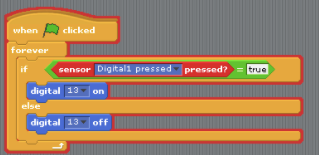
As I said, I’m not familiar with Scratch, so I decided to download and run the examples from the s4a.cat site. The first one is called “Button and LED”, and I thought: “OK, this is fine”. I downloaded and opened it but then suddenly it gave the error (Figure 3).

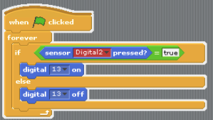
The problem seems to be in the “sensor ... pressed” block, as it has a red color. I clicked on the dropdown list and saw that Digital1 is not among allowed Digital input, so I replaced it with Digital2, and everything became fixed again (Figure 4).

Looking around and Writing our own “Program”
OK, now we know that at least something works here. Now it’s time to look around and see what we have here. In the left part of the screen, we can see the available blocks (Figure 5).

As you can see, they are grouped into 8 categories: Motion, Looks, Sound, Pen, Control, Sensing, Operators, and Variables. The blocks are quite intuitive. Not all of them are related to the Arduino, though. Some just allow you to make PC-related things, like play the sound or show some text. But these actions can be controlled by the Arduino as well, which is fun.
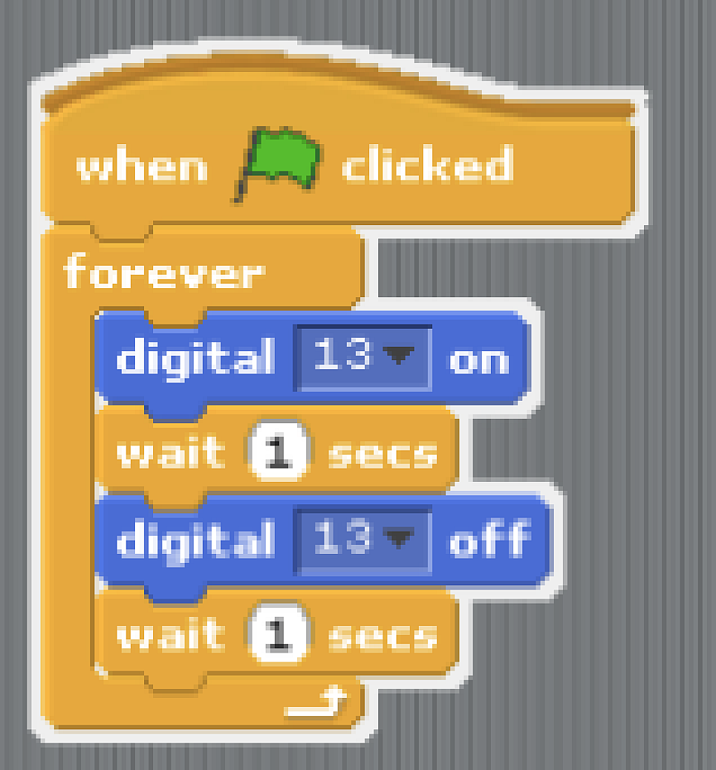
Let’s now try to write a simple LED blinking “program”. We have the on-board LED connected to pin 13, and fortunately, this pin acts as digital output in S4A. We need blocks “When <green flag> clicked”, “forever”, and “wait … secs” from the Control group; and “digital … on” and “digital … off” from the Motion group. The connection of the blocks is very simple and intuitive. If operations should be consecutive, you put one block under another; if they are nested, you just put one block inside another. The resulting diagram is shown in Figure 6.

As you can see, everything is very simple - you don’t even need to do any initializations, just the infinite loop, inside which you consequently turn digital pin 13 on, perform the delay, then turn it off, and perform another delay. This “program” is very similar to the “Blink” Arduino example (see the previous tutorial).
And, frankly, that’s all I wanted to tell you about the S4A project. If you are familiar with Scratch, you can find it useful with the additional functionality. Also, if you want to dive deeper into it, you can watch the video tutorials on the s4a.cat page, they talk about how to build a fully functioning robot using the S4A.
As for me, this is just a toy which is good to make some simple things or to encourage children to start programming but for serious projects, you’ll have to use text languages. Well, maybe I’ll reconsider my position, much as I did with the Arduino itself but... we’ll see.
Next time I will familiarize you with the Digispark board which, while being tiny, can’t be called a toy, as it allows you to make some cool things, unavailable even with the Uno board. So see you soon!

Get the latest tools and tutorials, fresh from the toaster.


