Hands-on with the MPLAB Code Configurator (MCC) | Embedded C Programming - Part 3
Published
Hi again! In this tutorial, I want to show you how to implement the same task as in the previous one (blinking the LED) but using the MPLAB Code Configurator (MCC). So if you haven’t disassembled the circuit yet, don’t do it because we will use it unchanged one more time. I’ll reuse the schematics diagram here (Fig. 1).

In the previous tutorial, I showed you how to create a new project in MPLAB X IDE. So let’s now create another project and call it Blink_MCC. Don’t create any source files because the MCC will do this for us. Now we need to click on the MCC icon in the toolbar, which is marked with the red box in Fig. 2.

You will see the MCC Content Manager Wizard (Fig. 3)
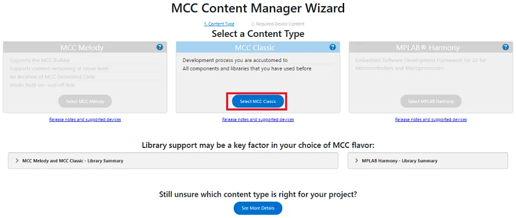
There is only one option that is not grayed - MCC Classic, so we select it (see the red box in Fig. 3). Then you will see another step in which you can add some optional content (Fig. 4).
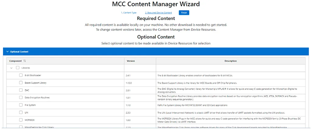
You can scroll down to see all available options but for now we don’t need any of them, so just click “Finish” without selecting anything. Finally you will see the following screen (Fig. 5)
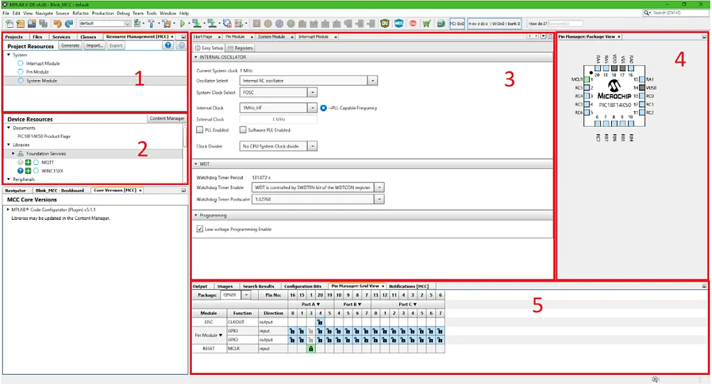
The window is divided into several areas:
- Resource Management (MCC). Here, the resources that are added to the project are listed. By default there are Interrupt Module, Pin module, and System module. We will consider all of them later.
- Device Resources. This is the list of resources available for this specific MCU. You can scroll down to see what hardware resources are available. In this project we won’t add anything from this list, so for now just skip it.
- Main Window. The main area where you can change the resources. As you can see, there are three tabs that are listed in the Resource Management area. We will make the majority of changes in this area.
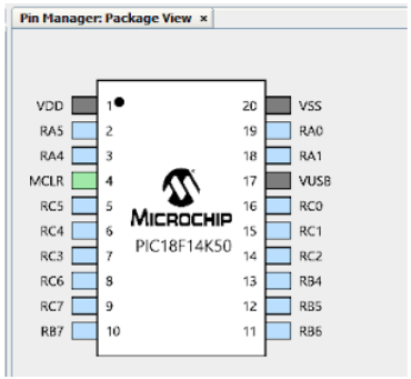
- Pin Manager: Package View. This is a convenient visual representation of your MCU which shows which pins of the MCU are used and what functions they do. As you can see, all pins except for MCLR are unused so far. Also you can notice that by default the package is set as QFN20, so we will need to change it to the one we have.
- Pin Manager: Grid View. This is a grid representation of the pin using. Here you can again see that only the MCLR pin has a lock, which means it’s already in use. In this area you can select the package type. There is a drop-down list in the top-left part of this area, where you can choose the package. For example, if you select the PDIP20, you will see that in area 4, the package type is also changed (Fig. 6)
OK, now that we’re more familiar with the MCC, let’s consider in more detail what we can do with it.
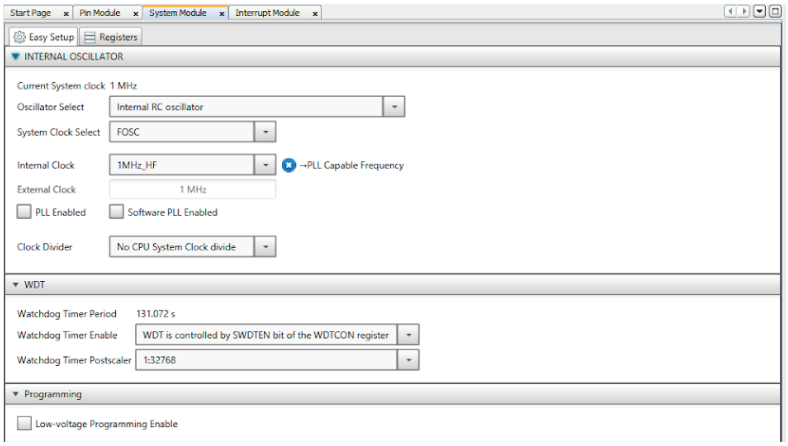
In Fig. 5 you can see the System Module tab opened in area 3. Here we implicitly set the configuration bits and also do the system clock setup. By the way, here you can see that the default values are set in a normal way, so the Internal RC Oscillator is selected and WDT is disabled. You only need to deselect the “Low-voltage Programming Enable” check. Also, you can select the internal clock value here and enable the PLL if needed, but let’s consider these things later when needed, and for now leave everything as is. After all this, this tab should look like this (Fig. 7).
To the right of the System Module there is the Interrupt Module tab (Fig. 8)
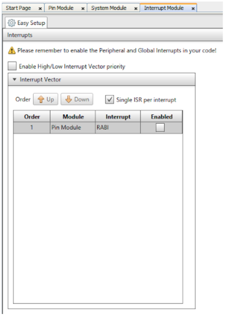
As we’re not going to use any interrupts in the current project, we leave this tab unchanged and switch to the Pin Module (Fig. 9).
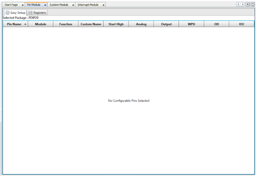
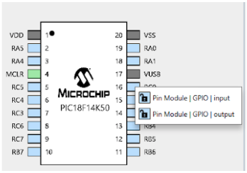
It’s empty for now because we didn’t configure any pins. Let’s fix this and configure the pin RC0, to which the LED1 is connected (Fig. 1) as an output. To do this we need to right click on the RC0 pin in the Pin Manager: Package View (Fig. 10) and select “Pin Module | GPIO | output”
After that you will see that this pin has appeared in the Pin Module table (Fig. 11)

Let’s now consider this table in more detail.
The first column Pin Name represents the name of the MCU pin. This name can’t be changed.
The Module column shows to which module the pin belongs; as now it is used as a general purpose I/O, it belongs to the Pin Module.
The Function column displays the current function of the pin. As I mentioned in the previous paragraph, it’s now a general purpose I/O, or GPIO.
The Custom Name column allows setting the custom name to each pin to make its usage more clear. We can change it to LED1.
The Start High column is applicable only to output pins, and allows the output to start with a high level after startup.
The Analog column allows to enable/disable the analog buffer on the corresponding pin. This buffer doesn’t affect the pin application in the digital mode, but it is better to turn it off for power saving.
The Output column selects the pin function: output if check is set or input if it’s clear.
The WPU, OD, and IOC columns will be considered later, when we need them. For now that’s enough information about the Pin Module.
So after all changes your table should look as follows (Fig. 12).

Actually, that’s all the required configuration. Now let the MCC generate the code by clicking on the “Generate” button in the Resource Management area (Fig. 13).

In the MPLAB Code Configurator tab in the bottom part of the window you will see the information “INFO: Generation complete.” This means that the code has been generated successfully, and now we can switch to it. To do this we need to select the “Projects” tab in the left top corner (Fig. 14).
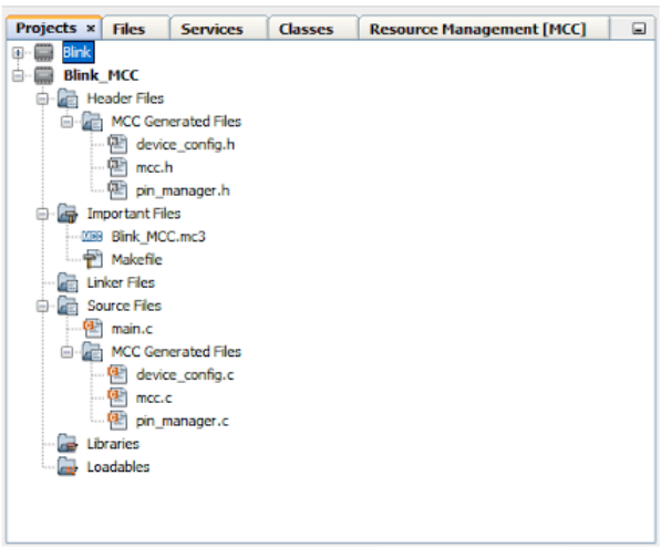
Here you can see that the MCC has created two folders named “MCC Generated Files” in the “Header files” and “Source files” folder. It has also created the “Blink_MCC.mc3” file in the “Important files” folder, this is the MCC file itself. And finally, it created the “main.c” file for us where we can write our code. It’s not recommended to change the content of the “MCC Generated Files” folders but it’s quite useful to get familiar with their files.
Also, in the “device_config.h” file you can see the definition of the CPU frequency which we had to write manually in the previous tutorial:
#define _XTAL_FREQ 1000000
In the “device_config.c” file you can find all the configuration bits that are set according to our selection in the System Module (Fig. 15).
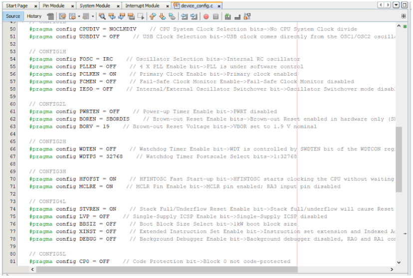
In files “mcc.h” and “mcc.c” there are declarations and implementations of the startup configuration functions.
The most interesting file for us is the “pin_manager.h” (Fig. 16)
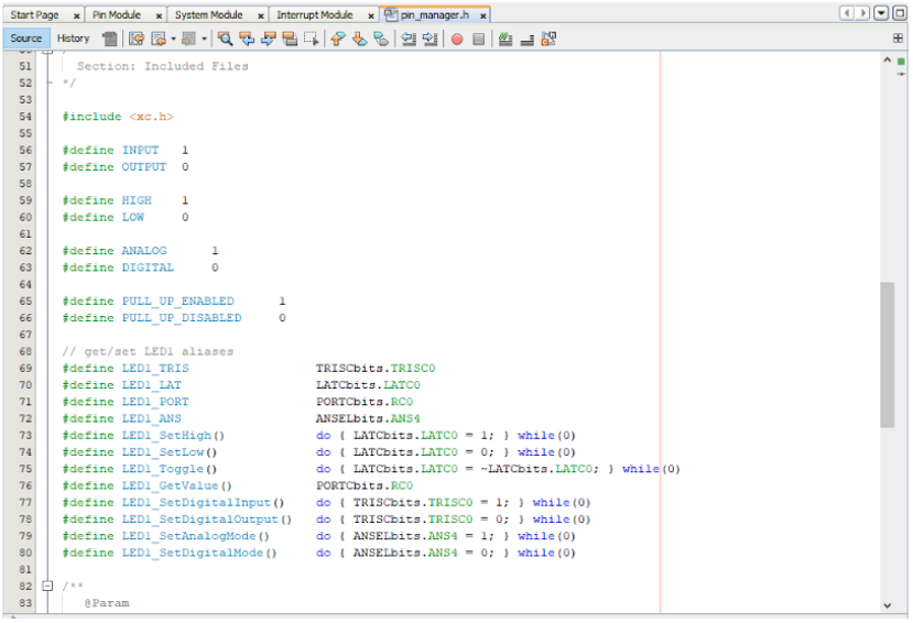
It provides the macro definitions which allow operating with the pins using easy-to-remember names. Also, as you can see, these names start with the custom name that we gave to the pin, in our case it’s LED1. So there is no need to remember the registers names and functions. For instance, to configure this pin as output you just need to write LED1_SetDigitalOutput(). Quite convenient, huh?
The “pin_manager.c” file contains the pins initialization function PIN_MANAGER_Initialize. It sets the I/O registers according to the settings of the Pin Module of MCC (Fig. 17).
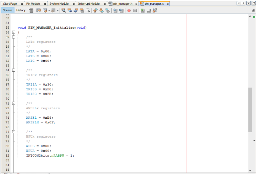
Some registers like TRISx and LATx are already familiar to you, the rest will be considered later.
Now that we’ve considered all files created by MCC, let’s now open the “main.c” file and add some code. As you noticed, until this moment, we haven’t written any lines manually.
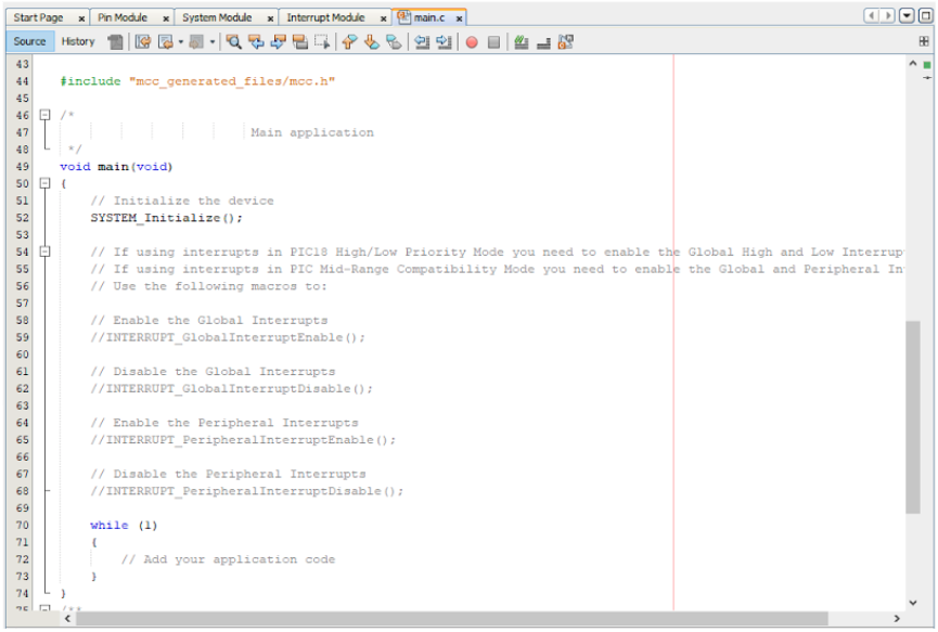
As you can see in Fig. 18 the majority of “main.c” is occupied by comments. Lines 1-42 contain the copyright information. Lines 54-68 remind us that we need to use certain functions if we are going to use interrupts, but we are not, so we can freely delete these lines. And finally, line 72 prompts us to write our code there. Let’s do it.
#include "mcc_generated_files/mcc.h"

void main(void)
{
	SYSTEM_Initialize();

	while (1)
	{
   	   LED1_Toggle();
   	   __delay_ms(500);
	}
}
Let’s consider this program in detail. I highlighted the code written manually with the green color. As you see, now instead of including the “xc.h” file we include “mcc_generated_files/mcc.h”. It already has all required includes, as I mentioned before.
The SYSTEM_Initialize() function implements the startup initialization of the oscillation module and pin module. The “PIN_MANAGER_Initialize” function (Fig. 17) is also invoked inside it. So now we have all the modules configured properly, and we can write our own code.
In line 9 there is LED1_Toggle function which was found in the “pin_manager.h” file (Fig. 16). According to its name it will toggle the LED1.
In line 10 there is the __delay_ms(500) function which we are familiar with from the previous tutorial.
And that’s it! We had to write just 2 lines of code! Perhaps in such a simple program when you know the registers names, it’s probably easier to just write several lines like we did in the previous tutorial, but in the complex application where almost all peripheral modules are used, the MCC saves a lot of time which otherwise would be spent by reading the data sheets and manuals.
Let’s now compile the code, connect the programmer, don’t forget to configure it so it can power the board, and finally download the code into the MCU. Now everything should work as desired without any problems right out of the gate.
By the way, you can see the memory usage in the dashboard, and notice that program memory usage increased from 38 bytes in the previous tutorial to 138 bytes in the current one. Well, that’s the price you have to pay for simplicity of code writing. In large projects this difference will not be that big though, and an extra 100-200 bytes is not a problem for the 16kB MCU.
And that’s it for now. In this tutorial we got acquainted with the MCC which allows us to configure the MCU using convenient visual tools. The price for this is increased code size but nothing is free.
Later I will alternate the tutorials, showing how to make the same things using the bare registers or the MCC. So you can compare the pros and cons of each approach and select the one you like better.
The homework is the same as in the previous tutorial: flash two LEDs in antiphase, so when one LED is on, the other is off, and vice versa. Try to do it by writing just three lines of your own code.

Get the latest tools and tutorials, fresh from the toaster.


