Integrating Buttons with a Microcontroller | Embedded C Programming - Part 4
Published
Hi there! In the previous tutorial, we figured out how to use the MPLAB Code Configurator to create a simple Blink program. This time we’ll move forward and add another part to the schematics - a button. The task for today is quite simple - to toggle the LED state every time the button is pressed.
Here is the schematic diagram to implement the current task (Fig. 1).

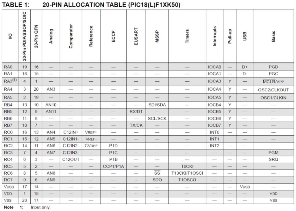
As you can see, it is very similar to the previous one, the only additional part is the tactile switch or button S1. One end of which is connected to the RB6 pin of the MCU and the other end is connected to ground. This pin was not selected randomly, and to explain this choice, I need to refer to Table 1 (which I already put in this tutorial: Programming PIC in C - 2. Our First Program).
As you know, for a button to work properly, you need to use a pull-up resistor. And if you don’t, you can refer to this tutorial where I explained its application: Button Inputs - Part 9 Microcontroller Basics (PIC10F200).
Like the PIC10F200, the PIC18F14K50 MCU has internal pull-up resistors on several pins. The list of pins which have these resistors is listed in Table 1, column “Pull-up”. You may notice that there are pull-ups only on the RA3-RA5 and RB4-RB7 pins.
All pins of Port A have alternative functions (column “Basic” in Table 1) so it’s better not to use them unnecessarily. Pins RB4 and RB5 have joint Analog functions (column “Analog” in Table 1), so they are configured as ADC inputs by default. I don’t want to overload you with a lot of extra information, so for now let’s just not use these pins as well. Finally, we only have RB6 and RB7 pins which can be used without any problems or additional configuration. That’s why I connected switch S1 to the RB6 pin (Fig. 1) but you can also use the RB7 pin if you want.
Let’s now create a new project (like I showed you in this tutorial: Programming PIC in C - 2. Our First Program) and write the code which will implement the given task.
// PIC18F14K50 Configuration Bit Settings
// 'C' source line config statements

// CONFIG1L
#pragma config CPUDIV = NOCLKDIV                       // CPU System Clock Selection bits (No CPU System Clock divide)
#pragma config USBDIV = OFF                                  // USB Clock Selection bit (USB clock comes directly from the OSC1/OSC2 oscillator block; no divide)


// CONFIG1H
#pragma config FOSC = IRC                                // Oscillator Selection bits (Internal RC oscillator)
#pragma config PLLEN = OFF                                      // 4 X PLL Enable bit (PLL is under software control)
#pragma config PCLKEN = ON                        // Primary Clock Enable bit (Primary clock enabled)
#pragma config FCMEN = OFF                                             // Fail-Safe Clock Monitor Enable (Fail-Safe Clock Monitor disabled)
#pragma config IESO = OFF                                          // Internal/External Oscillator Switchover bit (Oscillator Switchover mode disabled)


// CONFIG2L
#pragma config PWRTEN = OFF                              // Power-up Timer Enable bit (PWRT disabled)
#pragma config BOREN = SBORDIS                                    // Brown-out Reset Enable bits (Brown-out Reset enabled in hardware only (SBOREN is disabled))
#pragma config BORV = 19                                        // Brown-out Reset Voltage bits (VBOR set to 1.9 V nominal)


// CONFIG2H
#pragma config WDTEN = OFF                            // Watchdog Timer Enable bit (WDT is controlled by SWDTEN bit of the WDTCON register)
#pragma config WDTPS = 32768                     // Watchdog Timer Postscale Select bits (1:32768)


// CONFIG3H
#pragma config HFOFST = ON                                       // HFINTOSC Fast Start-up bit (HFINTOSC starts clocking the CPU without waiting for the oscillator to stablize.)
#pragma config MCLRE = ON                                        // MCLR Pin Enable bit (MCLR pin enabled; RA3 input pin disabled)


// CONFIG4L
#pragma config STVREN = ON                               // Stack Full/Underflow Reset Enable bit (Stack full/underflow will cause Reset)
#pragma config LVP = OFF                                                // Single-Supply ICSP Enable bit (Single-Supply ICSP disabled)
#pragma config BBSIZ = OFF                                                         // Boot Block Size Select bit (1kW boot block size)
#pragma config XINST = OFF // Extended Instruction Set Enable bit (Instruction set extension and Indexed Addressing mode disabled (Legacy mode))


// CONFIG5L
#pragma config CP0 = OFF                                               // Code Protection bit (Block 0 not code-protected)
#pragma config CP1 = OFF                                                // Code Protection bit (Block 1 not code-protected)


// CONFIG5H
#pragma config CPB = OFF                                        // Boot Block Code Protection bit (Boot block not code-protected)
#pragma config CPD = OFF                                            // Data EEPROM Code Protection bit (Data EEPROM not code-protected)


// CONFIG6L
#pragma config WRT0 = OFF                                  // Table Write Protection bit (Block 0 not write-protected)
#pragma config WRT1 = OFF                                   // Table Write Protection bit (Block 1 not write-protected)


// CONFIG6H
#pragma config WRTC = OFF                                     // Configuration Register Write Protection bit (Configuration registers not write-protected)
#pragma config WRTB = OFF                                    // Boot Block Write Protection bit (Boot block not write-protected)
#pragma config WRTD = OFF                                         // Data EEPROM Write Protection bit (Data EEPROM not write-protected)


// CONFIG7L
#pragma config EBTR0 = OFF                          // Table Read Protection bit (Block 0 not protected from table reads executed in other blocks)
#pragma config EBTR1 = OFF                            // Table Read Protection bit (Block 1 not protected from table reads executed in other blocks)


// CONFIG7H
#pragma config EBTRB = OFF                                    // Boot Block Table Read Protection bit (Boot block not protected from table reads executed in other blocks)


// #pragma config statements should precede project file includes.
// Use project enums instead of #define for ON and OFF.


#define _XTAL_FREQ 1000000 //CPU clock frequency


#include <xc.h>           //Include general header file


void main(void)          //Main function of the program
{
           TRISCbits.TRISC0 = 0;     //Configure RC0 pin as output
           TRISBbits.TRISB6 = 1;       //Configure RB6 pin as input
           WPUBbits.WPUB6 = 1;      //Enable pull-up resistor at RB6 pin
           INTCON2bits.nRABPU = 0;  //Allow pull-up resistors on ports A and B
           while (1)                    //Main loop of the program
           {
           if (PORTBbits.RB6 == 0) //If button is pressed (RB6 is low)
           {
           __delay_ms(20);  //Then perform the debounce delay
           if (PORTBbits.RB6 == 0)  //If after the delay RB6 is still low
           {
                      while (PORTBbits.RB6 == 0);    //Then wait while button is pressed
                      __delay_ms(20);                                          //After button has been released, perform another delay
                      if (PORTBbits.RB6 == 1)                                //If the button is released after the delay (RB6 is high)
                      {
                      LATCbits.LATC0 ^= 0x01;                         //Then perform the required action (toggle RC0 pin)
                      }
           }
           }
           }
}
Lines 1 - 59 were generated automatically by the “Configurations bits” section. I explained how to use it in this tutorial Programming PIC in C - 2. Our First Program. They will be the same or very similar in the following tutorials as well, so if there are no changes I’ll just skip the explanation of this part, otherwise I’ll point out the changes and tell why they are required.
In the current tutorial they are the same as in the previous one, so let’s move to line 60. It is also familiar to you, it’s the CPU clock definition required by the delay function.
Line 62 is also the same as in the previous tutorial, so I won’t stop on it.
The main function of the program (lines 64-86) starts with configuring RC0 pins as an output by resetting the corresponding TRISC bit to 0 (line 66). Then we configure the RB6 pin as an input by setting the bit 6 of the TRISB register to 1 (line 67).
In line 68 there is a new register called WPUB. This register enables the pull-up resistor on the specific pin of the Port B. As I mentioned before, only ports A and B have the ability to enable the pull-up resistors, so there are registers WPUA and WPUB, but not WPUC. In line 68, we use the familiar construction WPUBbits which allows us to operate with each bit. In our case we need to enable the pull-up resistor on pin RB6, thus we write
WPUBbits.WPUB6 = 1;
In line 69 we meet another new register - INTCON2. As follows from its name there are several registers with the same name but different numbers. Actually there are three of them: INTCON, INTCON2, and INTCON3. These registers are used for interrupt control. I don’t know why but besides the interrupt control, there is a bit called RABPU (this is bit #7, just FYI) in the register INTCON2 which allows using the pull-up resistors in general. To me, this bit isn’t related to the interrupts system but who I am to argue with the Microchip developers? So, in line 69 we see the text
INTCON2bits.nRABPU = 0;
The “bits” suffix should be already very familiar to you, so I’ll not dwell on it. The bit RABPU (ports RA and B Pull-Up) has the prefix “n”. It means that the bit has the inverted value. Thus when the RABPU bit is reset to 0 then the pull-up resistors are allowed, and when it’s set to 1, they are disabled. The default value of this bit is 1, so we need to reset it to use the pull-up resistors, which we do here, in line 69.
I will talk about the other bits of the INTCONx registers when I talk about the interrupts but for now we’ll skip them.
This is the last line of the configuration part. The next lines (70 to 85) are the main loop of the program.
The algorithm of the button processing was described in this tutorial: Button Inputs - Part 9 Microcontroller Basics (PIC10F200) but I’ll repeat it briefly with the C language.
In line 72, we check if the bit RB6 of the register PORTB is 0. This register represents the actual input state of the pin, so we need to use it to check the button state. If the button is not pressed, then the pin state will be 1 because of the pull-up resistor. When we press the button, the second end of which is connected to the ground, the state of the pin will become 0. So, in line 72 we actually check if the button is pressed.
After registering the first moment when the button was pressed, we perform the debounce delay of 20 ms (line 74). If the button isn’t very good quality, then the debounce delay time may be increased. After this time we check one more time if the button is still pressed (line 75). If it is (which means that it was not a false signal) then we wait all the time while the button is pressed and just do nothing. This is implemented by means of the while loop (line 77). When the loop condition becomes false, which means that the button has been released, then we perform another debounce delay (line 78). After that we check if the pin RB6 is high (line 79). If it is, that means the button has truly been released. And only after that do we perform the required action. In our case, it’s toggling the LED (line 81) but this can be any action you need.
As you see, in C language this looks almost the same as in Assembly language, despite in C we use the high-level functions and operations, and in Assembly we use the MCU instructions. The code size of the C-based program is 120 bytes while the Assembly-based program is just 43 bytes, even taking into account that the Assembly program processes two buttons. And again, this is the price of the simplicity of using the high-level language.
Now you can assemble the circuit according to Fig. 1, compile the code, and download it into the MCU. If everything is done correctly, the LED will change its state every time you press the button. If the operation is not consistent, try to increase the debounce delay. If nothing works at all, double check the connection.
That’s it for now. Today we learned how to operate with a button in C language, and got acquainted with two new registers: WPUx and INTCON2.
As homework, change the program to blink the LED with the frequency of 4 Hz while the button is pressed. After releasing the button, turn off the LED.
Hope to see you soon despite these hard and unpredictable times.

Authored By
Sergey Sokol
I was born, raised, and currently live in Ukraine. I’m fond of different types of electronics and backpacking but these things have been set aside with the war that has been thrust on my country, my people, and my family. Through these trials, if you could help support me financially, I would appreciate any help that could be sent via Paypal to sokolsp@gmail.com

Related Tutorials
 | Embedded C Programming - Part 3")
Related EE FAQs
 work?")
How do Analog to Digital Converters (ADCs) work?

Answered by Uma Bharathi D

What's the difference between a regular relay and a power relay?

Answered by Jayesh Upadhyay

What is a PWM signal?
Answered by Jayesh Upadhyay

Why is RAM faster than other memories?
Answered by Jayesh Upadhyay
Explore CircuitBread
- 244 Tutorials
- 9 Textbooks
- 12 Study Guides
- 31 Tools
- 104 EE FAQs
- 295 Equations Library
- 213 Reference Materials
- 97 Glossary of Terms
Friends of CircuitBread
-

Search Hundreds of Component Distributors + 2 Perks
-

Product Samples Available by Request
-

Product Samples Upon Request


Get the latest tools and tutorials, fresh from the toaster.


